logo elektroda
logo elektroda
X
logo elektroda

How to connect a smart switch without N to a contactor in a 2-wire installation?

konsum 537 7
ADVERTISEMENT
Treść została przetłumaczona polish » english Zobacz oryginalną wersję tematu
  • #1 21874999
    konsum
    Level 27  
    Posts: 1499
    Help: 99
    Rate: 289
    Hi.
    I'd like some advice, I'm more concerned with gaining theoretical knowledge as this is more of a conundrum that an electrician will have to deal with, namely.
    I have a street light which I switch on with a normal light switch and a contactor is switched on, I wanted to install a smart switch so that this light starts automatically etc.
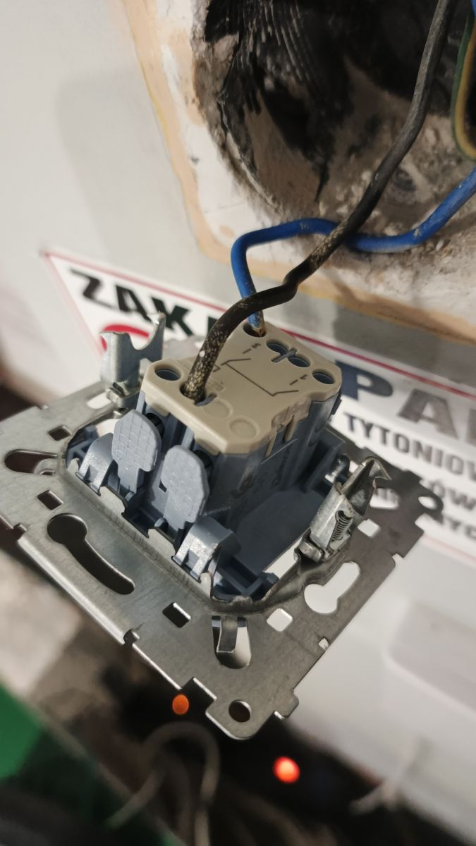
    The switch has a two wire installation, black phase and blue where the voltage appears when the light is switched on.
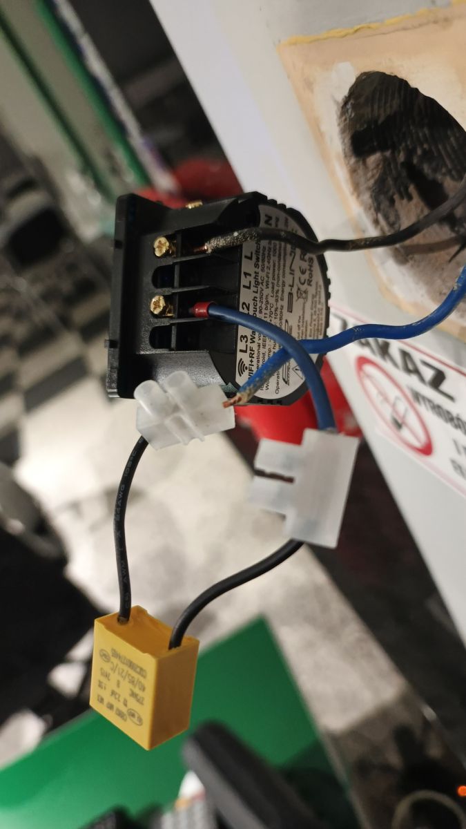
    I fitted the smart switch to the installation without Neutral initially without the capacitor that was attached for proper operation without the Neutral wire and when I turn on the light the contactor starts the lighting comes on, but after a fraction of a second it turns off because the switch loses power and regains it after a while.
    When I fitted a capacitor it works in a similar way, only that the power is maintained for a while longer and then it goes out again and switches off.
    Would anyone be so good as to advise if there is any way to make this switch work?
    I would add that there is a spare yellow/green wire in the box from the switch and once fetched I consulted an electrician he said it could be used to power this switch.
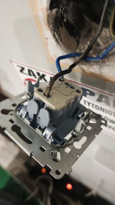
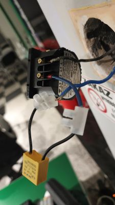
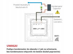
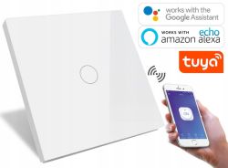
    Close-up of a light switch mechanism with connected wires inside a wall box Smart switch module in a wall box with connected wires and a yellow capacitor on connectors Wiring diagram for B-LINE Wi‑Fi switch with capacitor, live L and neutral N wires, and a lamp White smart touch light switch with Google Assistant, Alexa and Tuya logos; phone shows ON button
  • ADVERTISEMENT
  • #2 21875007
    78db78
    Level 43  
    Posts: 10423
    Help: 1780
    Rate: 3192
    It's not working properly because you don't have a load just a contactor coil.
    When does this lighting come on? You can give something else.
  • ADVERTISEMENT
  • #3 21875008
    tos18
    Level 42  
    Posts: 7033
    Help: 1093
    Rate: 1817
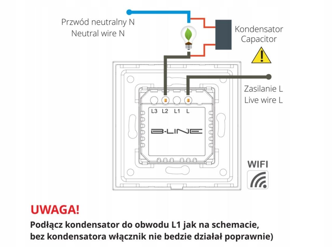
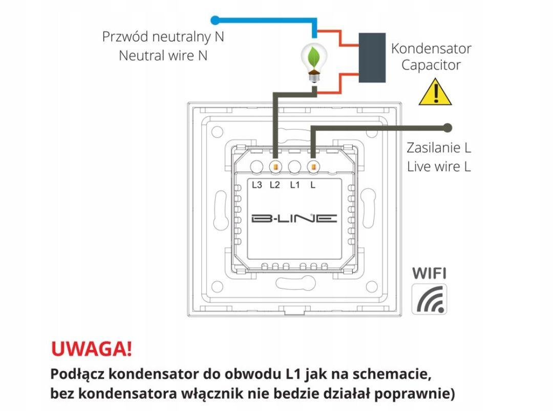
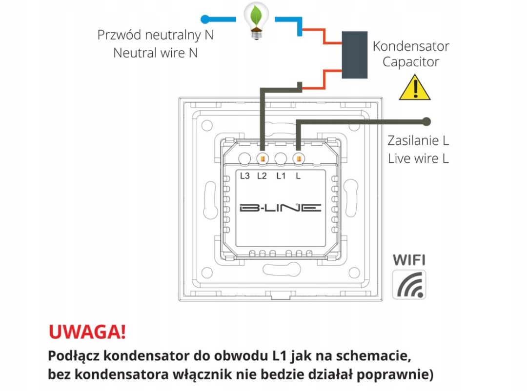
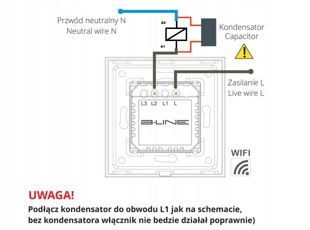
    You have connected it incorrectly according to the diagram
    it is supposed to be:

    Wiring diagram for B-LINE WiFi switch with capacitor, neutral N wire, and live L supply

    you have done :

    Wiring diagram for B-LINE switch module with capacitor connected to L1 and lamp circuit

    konsum wrote:
    Add that in the box from the switch there is a free wire in yellow-green colour and once downloading I consulted it with the electrician and he said that it can be used to power this switch.

    Tell the electrician to suggest such a solution at the qualification exam (he passes one every 5 years).
  • ADVERTISEMENT
  • #4 21875013
    konsum
    Level 27  
    Posts: 1499
    Help: 99
    Rate: 289
    tos18 wrote:
    Tell the electrician to propose such a solution at the qualification exam (he passes one every 5 years).

    I think what he meant was that you can switch this wire in the switchboard and make it neutral.

    tos18 wrote:
    You have connected this contrary to the schematic

    Unfortunately I have no way of getting to those tubes to connect that capacitor there.
    But is the capacitor to blame for this switch not working properly?

    Added after 2 [minutes]:

    78db78 wrote:
    When does this lighting come on?

    I start it manually with a switch and it is switched on by a contactor.
    78db78 wrote:
    When does this lighting actuate?

    78db78 wrote:
    You can give something else

    I.e.?
  • ADVERTISEMENT
  • #5 21875021
    78db78
    Level 43  
    Posts: 10423
    Help: 1780
    Rate: 3192
    konsum wrote:
    I start it manually with a switch and it is switched on by a contactor.
    78db78 wrote:
    When does this lighting come on?

    78db78 wrote:
    You can give something else

    I.e.

    Astronomical clock programmer.
  • #6 21875053
    tos18
    Level 42  
    Posts: 7033
    Help: 1093
    Rate: 1817
    konsum wrote:
    tos18 wrote:
    Tell the electrician to propose such a solution at the qualification exam (he passes one every 5 years).

    I think what he meant was that you can switch this wire in the switchboard and make it neutral.

    hands are falling off.

    konsum wrote:
    Unfortunately I have no way of getting to those lamps to connect that capacitor there.

    Why to the lamps if the switch controls the contactor ? - in parallel to the coil of the contactor.

    Wiring diagram for B‑LINE Wi‑Fi switch with neutral N, live L, and a capacitor connected to L1

    78db78 wrote:
    Astronomical clock programmer.

    Installed in the switchboard next to the contactor where N will be available.
  • #7 21876186
    konsum
    Level 27  
    Posts: 1499
    Help: 99
    Rate: 289
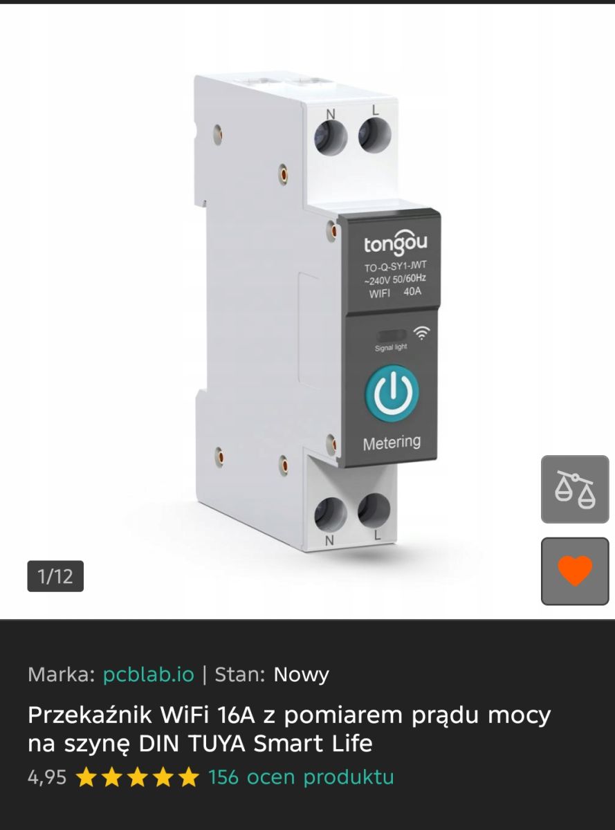
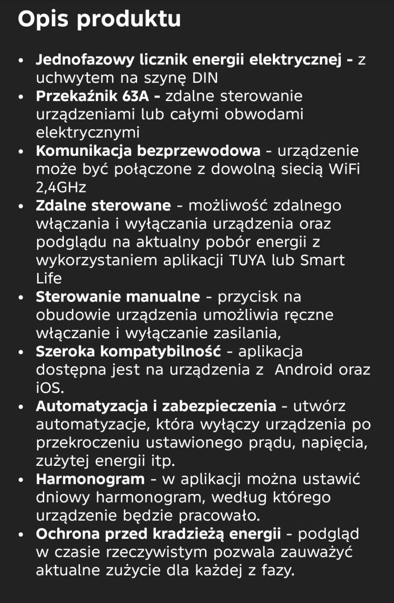
    And what do you think such a smart relay I can use and will work well with this installation?

    Tongou DIN-rail Wi‑Fi relay with N and L terminals shown in a product listing screenshot Screenshot titled “Opis produktu” listing features of an energy meter and 63A Wi‑Fi relay
  • #8 21876449
    kmarkot
    Level 31  
    Posts: 1366
    Help: 126
    Rate: 358
    konsum wrote:
    the contactor is connected

    Connect in parallel to the contactor
    https://allegro.pl/oferta/eliminator-rozblyskow-zarowek-led-kondensator-wksl-13101838215
    >>21876186
    Instead of a contactor, this energy meter can be connected. It will not be possible to switch on manually and only with the switch, the one that has been on the wall so far.
ADVERTISEMENT