





1. Introduction to Raspberry Pi Pico
The Raspberry Pi Pico is a low-cost, high-performance microcontroller development board officially designed by Raspberry Pi, featuring flexible digital interfaces. In terms of hardware, it adopts the RP2040 microcontroller chip independently developed by Raspberry Pi official, is equipped with an ARM Cortex-M0+ dual-core processor, has an operating frequency of up to 133MHz, integrates 264KB of SRAM and 2MB of memory, and also comes with as many as 26 multifunctional GPIO pins on board.In terms of software, you can choose the C/C++ SDK provided by Raspberry Pi or use MicroPython for development. It is also equipped with complete development materials and tutorials, which facilitates quick entry into development and embedding applications into products.
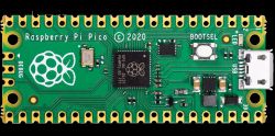
Figure 1.1 Front View of Raspberry Pi Pico Development Board
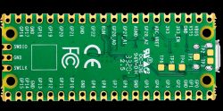
Figure 1.2 Back side of the Raspberry Pi Pico development board
2. Hardware Circuit of Pico Development Board
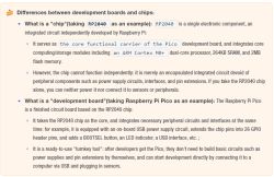
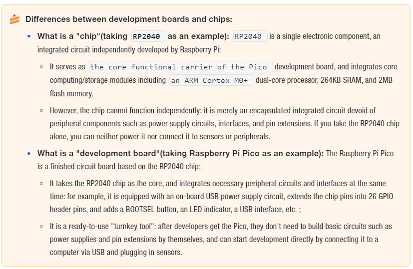
Beginners can think of the RP2040 chip as "a smartphone motherboard without a screen, battery or buttons" — it has core functions but cannot work without these accessories. These hardware circuits supplement the chip with essential functions such as "power supply, clock generator, status indicator and interfaces", turning the Pico from a "bare chip" into a "directly usable development board".
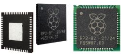
The Raspberry Pi Pico is equipped with some peripheral circuits of the RP2040 chip, including passive components such as an external Flash memory chip (W25Q16JV), a clock crystal oscillator, and power filter capacitors, as well as a USB connector, a reset button, and an LED indicator. Most of the available pins of the RP2040 chip are led out on both sides of the Pico development board, and four pins are reserved for internal functions, including driving the onboard LED, powering the development board, and selecting the BOOT mode.
The schematic diagram of the Raspberry Pi Pico is shown below, which consists of an external clock crystal oscillator circuit, a BOOT mode selection circuit, a power supply input circuit, a power supply voltage measurement circuit, an LED indicator driving circuit, a debugging interface circuit, a pin expansion circuit and a chip peripheral circuit, and we will introduce them one by one next.
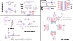
Figure 1.4 Circuit Schematic of Raspberry Pi Pico Development Board
Simply put, the peripheral circuits of a Pico development board consist of the following parts:
- Clock Crystal Oscillator Circuit: A circuit composed of a 12MHz crystal oscillator (labeled X1 in the diagram) and small components such as capacitors. It acts as the "metronome" for the chip — the chip's operations and communication with peripherals all rely on precise "time rhythm", and this circuit delivers a stable "beat signal" of 12 million cycles per second to ensure the chip works with accurate timing (for example, the 1-millisecond timed flashing of an LED is entirely timed based on this beat).
- BOOT Mode Selection Circuit: It is essentially a small circuit equipped with a BOOTSEL button, serving as the "boot mode toggle switch" for the chip. The chip has two modes during startup:
- Normal Mode: Launch the saved program;
- BOOT Mode: The firmware flashing state is the "program loading mode" of the Pico: after connecting the Pico to a computer while holding down the BOOTSEL button, the Pico will switch to this state (without launching the old program), at which point it will be recognized by the computer as a storage device. Simply drag the written program (firmware) into it, and you can install new functions on the Pico.
- Power Supply Input Circuit: This is the circuit in charge of power management (such as the power management chip U2 in the diagram). It supports input from either USB (5V) or a battery (2-5V), and will stably convert the input voltage to the 3.3V required by the chips, while filtering out clutter in the voltage to prevent voltage fluctuations from damaging the chips.
- Power Supply Voltage Measurement Circuit: A compact circuit designed to detect the power supply voltage. It acts as the "built-in voltmeter" of the board, capable of measuring the input power supply voltage in real time (for example, when powered by batteries, it lets you know if the batteries are running low), making it convenient for you to monitor the power status.
- LED Indicator Driving Circuit: A small circuit that controls the onboard LED. The chip can control the on/off state of this LED through the GPIO25 pin to display status (e. g., blinking when the program is running, steady on when the power is connected).
- Debug Interface Circuit: This refers to the DEBUG header (3-pin header) shown in the diagram, which acts as the "fault diagnosis port" of the board. If your program gets corrupted or the board stops working, you can connect a debugging tool to this interface to check the internal operating status of the chip and pinpoint where the program has gone wrong.
- Pin Expansion Circuit: A circuit that converts chip pins into header pins (labeled CON_PICO_40W in the diagram). The pins on the RP2040 chip itself are too small to connect wires directly; this circuit expands the chip pins into header pins, allowing you to use DuPont wires to plug directly into these headers to connect external components such as sensors and motors.
- Peripheral circuit of the chip: A circuit composed of small components such as filter capacitors and resistors around the chip. For example, filter capacitors can filter out the clutter in the power supply to make the power supply for the chip more stable; resistors can protect the pins from being burned out by excessive current, and prevent the chip from malfunctioning due to external interference or current fluctuations.
The Raspberry Pi Pico is a low-cost, high-performance microcontroller development board officially designed by Raspberry Pi, featuring flexible digital interfaces. In terms of hardware, it adopts the RP2040 microcontroller chip independently developed by Raspberry Pi official, is equipped with an ARM Cortex-M0+ dual-core processor, has an operating frequency of up to 133MHz, integrates 264KB of SRAM and 2MB of memory, and also comes with as many as 26 multifunctional GPIO pins on board.In terms of software, you can choose the C/C++ SDK provided by Raspberry Pi or use MicroPython for development. It is also equipped with complete development materials and tutorials, which facilitates quick entry into development and embedding applications into products.
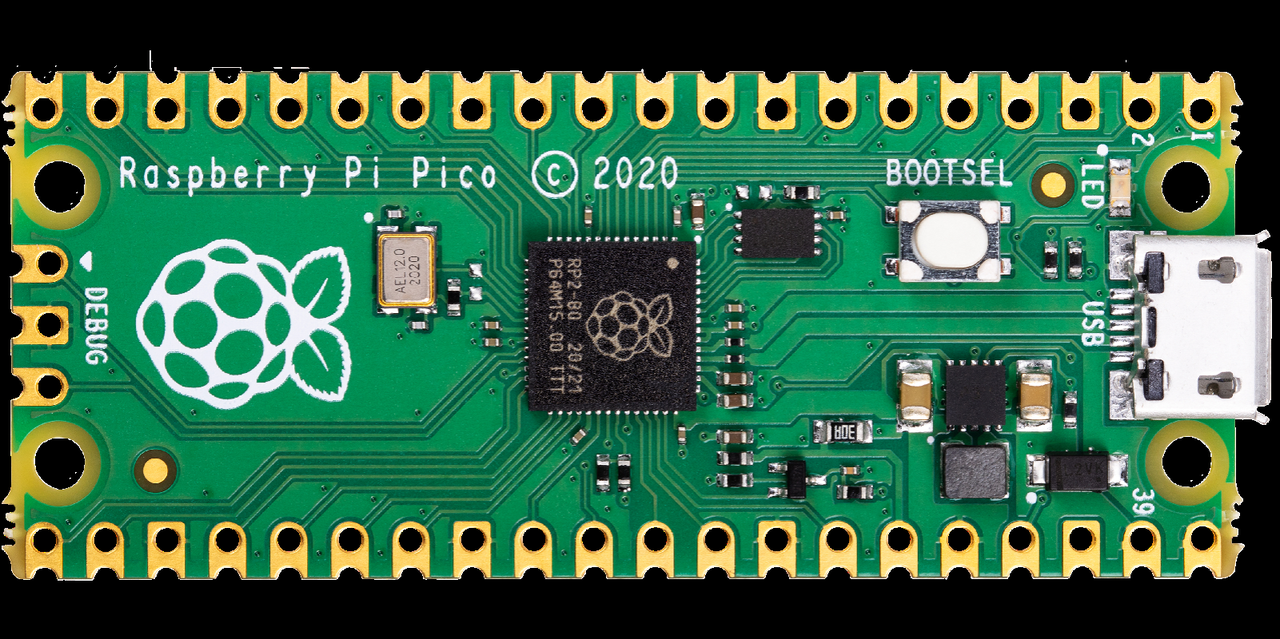
Figure 1.1 Front View of Raspberry Pi Pico Development Board
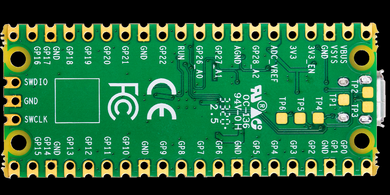
Figure 1.2 Back side of the Raspberry Pi Pico development board
2. Hardware Circuit of Pico Development Board
Beginners can think of the RP2040 chip as "a smartphone motherboard without a screen, battery or buttons" — it has core functions but cannot work without these accessories. These hardware circuits supplement the chip with essential functions such as "power supply, clock generator, status indicator and interfaces", turning the Pico from a "bare chip" into a "directly usable development board".
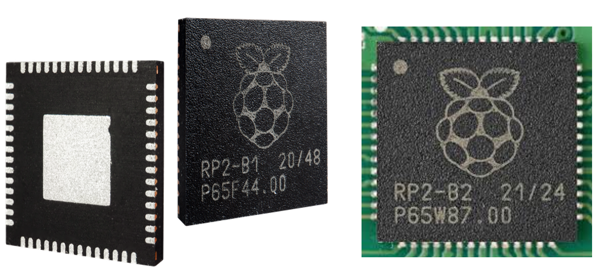
The Raspberry Pi Pico is equipped with some peripheral circuits of the RP2040 chip, including passive components such as an external Flash memory chip (W25Q16JV), a clock crystal oscillator, and power filter capacitors, as well as a USB connector, a reset button, and an LED indicator. Most of the available pins of the RP2040 chip are led out on both sides of the Pico development board, and four pins are reserved for internal functions, including driving the onboard LED, powering the development board, and selecting the BOOT mode.
The schematic diagram of the Raspberry Pi Pico is shown below, which consists of an external clock crystal oscillator circuit, a BOOT mode selection circuit, a power supply input circuit, a power supply voltage measurement circuit, an LED indicator driving circuit, a debugging interface circuit, a pin expansion circuit and a chip peripheral circuit, and we will introduce them one by one next.
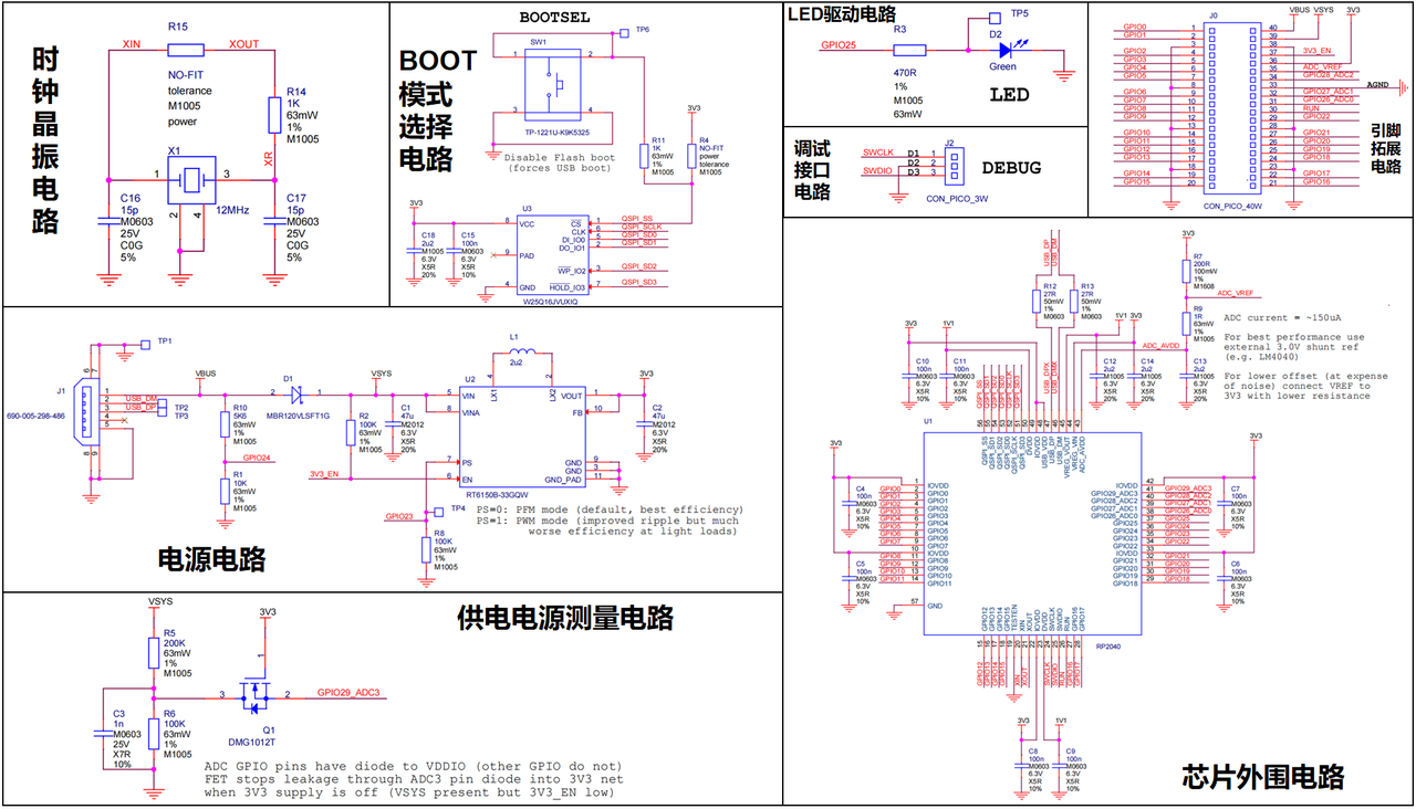
Figure 1.4 Circuit Schematic of Raspberry Pi Pico Development Board
Simply put, the peripheral circuits of a Pico development board consist of the following parts:
- Clock Crystal Oscillator Circuit: A circuit composed of a 12MHz crystal oscillator (labeled X1 in the diagram) and small components such as capacitors. It acts as the "metronome" for the chip — the chip's operations and communication with peripherals all rely on precise "time rhythm", and this circuit delivers a stable "beat signal" of 12 million cycles per second to ensure the chip works with accurate timing (for example, the 1-millisecond timed flashing of an LED is entirely timed based on this beat).
- BOOT Mode Selection Circuit: It is essentially a small circuit equipped with a BOOTSEL button, serving as the "boot mode toggle switch" for the chip. The chip has two modes during startup:
- Normal Mode: Launch the saved program;
- BOOT Mode: The firmware flashing state is the "program loading mode" of the Pico: after connecting the Pico to a computer while holding down the BOOTSEL button, the Pico will switch to this state (without launching the old program), at which point it will be recognized by the computer as a storage device. Simply drag the written program (firmware) into it, and you can install new functions on the Pico.
- Power Supply Input Circuit: This is the circuit in charge of power management (such as the power management chip U2 in the diagram). It supports input from either USB (5V) or a battery (2-5V), and will stably convert the input voltage to the 3.3V required by the chips, while filtering out clutter in the voltage to prevent voltage fluctuations from damaging the chips.
- Power Supply Voltage Measurement Circuit: A compact circuit designed to detect the power supply voltage. It acts as the "built-in voltmeter" of the board, capable of measuring the input power supply voltage in real time (for example, when powered by batteries, it lets you know if the batteries are running low), making it convenient for you to monitor the power status.
- LED Indicator Driving Circuit: A small circuit that controls the onboard LED. The chip can control the on/off state of this LED through the GPIO25 pin to display status (e. g., blinking when the program is running, steady on when the power is connected).
- Debug Interface Circuit: This refers to the DEBUG header (3-pin header) shown in the diagram, which acts as the "fault diagnosis port" of the board. If your program gets corrupted or the board stops working, you can connect a debugging tool to this interface to check the internal operating status of the chip and pinpoint where the program has gone wrong.
- Pin Expansion Circuit: A circuit that converts chip pins into header pins (labeled CON_PICO_40W in the diagram). The pins on the RP2040 chip itself are too small to connect wires directly; this circuit expands the chip pins into header pins, allowing you to use DuPont wires to plug directly into these headers to connect external components such as sensors and motors.
- Peripheral circuit of the chip: A circuit composed of small components such as filter capacitors and resistors around the chip. For example, filter capacitors can filter out the clutter in the power supply to make the power supply for the chip more stable; resistors can protect the pins from being burned out by excessive current, and prevent the chip from malfunctioning due to external interference or current fluctuations.
