logo elektroda
logo elektroda
X
logo elektroda
ADVERTISEMENT
Treść została przetłumaczona polish » english Zobacz oryginalną wersję tematu
  • Hello

    I honestly admit that I do not know yet what exactly will be built. For now, I am trying to run what I can from the interfaces available in the system.

    What is F1C100s? It is a Chinese SOC in the QFN88 housing with:
    - ARM9 processor (not to be confused with Cortex A9)
    - 32MB RAM (built-in DDR1)
    - LCD controller
    - camera input
    - composite input / output (TV in / out)
    - audio codec
    - resistive touch controller for LCD
    - USB / SD / MMU / DMA / Timers / ....
    The layout cost is approximately $ 2.

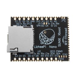
    I will be using the Lichee Pi Nano tile for my experiments.
    Some time ago I bought a few items and they were waiting for their turn.
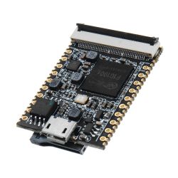
    Something on F1C100s by piotr_go Something on F1C100s by piotr_go

    The soft on which I base my experiments can be downloaded HERE .

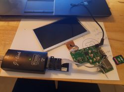
    At the moment I was able to run VGA (640x480) through the converter board connected to the LCD connector.


    I also have a matching LCD touchscreen that I will want to run.

    Cool? Ranking DIY
    About Author
    piotr_go
    DIY electronics designer
    Offline 
    piotr_go wrote 2837 posts with rating 3187, helped 91 times. Been with us since 2003 year.
  • ADVERTISEMENT
  • #2 18643288
    ArturAVS
    Moderator
    Cool baby :D It is a pity that I do not have enough programming knowledge, but with such resources (and dimensions) I would think of some SDR receiver. The built-in audio codec in the case of "W" can be replaced with an external one with better ADC parameters. The SDR front-end itself is very simple. It would be an interesting solution (SDR the size of a cigarette pack). You might even be tempted to build a full-fledged TRX QRP (you need two codecs, one for the TX and the second RX).
  • #3 18643646
    piotr_go
    DIY electronics designer
    ArturAVS wrote:
    The built-in audio codec in the case of "W" can be replaced with an external one with better ADC parameters.

    Codec on the list of things to run, right after SD. Currently I deal with LCD and touch.
    Of course, it's about soft without using Linux, so that the whole thing starts in less than a second.
  • #4 18643842
    ArturAVS
    Moderator
    While the DAC in the codec looks interesting (two 8-192kHz channels), the ADC is poor (one 8-48kHz channel). For the SDR you would need to provide an external two-channel ADC.
    piotr_go wrote:
    I was able to run VGA (640x480) through the converter board connected to the LCD connector.

    What is this converter? Maybe it's better some LCD with a touch after SPI (e.g. popular for arduino 320x240 etc.)? It is a pity that Lichee Pi Nano is unavailable in the country.
  • #5 18643872
    piotr_go
    DIY electronics designer
    ArturAVS wrote:
    What is this converter?

    Something on the "GM7123" scalak, probably ADV7123 clone.

    ArturAVS wrote:
    Maybe it's better some LCD with a touch after SPI (e.g. popular for arduino 320x240 etc.)?

    I have 800x480 torn from navigation. It works. I'll post a video tomorrow.
  • ADVERTISEMENT
  • #6 18643947
    ArturAVS
    Moderator
    piotr_go wrote:
    I have 800x480 torn from navigation

    I also have a few of them, I wonder if the pinout is correct.
  • #7 18644870
    piotr_go
    DIY electronics designer


    LCD, touch, UART, SPI FLASH are already working, so that HMI display can be done.
  • #9 18645296
    piotr_go
    DIY electronics designer
    There is no FPU so there could be a problem.
    However, there is a similar SOC - V3s with Cortex A7 core and FPU. The housing is only slightly larger (LQFP128).
  • #11 18647902
    piotr_go
    DIY electronics designer
    Yes. This one.


    ========= update 04/28/2020 =========

    I was supposed to run the SD first, but I started working on the DAC first.
    Sound, DMA, interrupts are working.

    Now there is SD.


    ========= update 4/30/2020 =========

    I launched the SD :)


    Now you will have to write some interesting soft.
  • ADVERTISEMENT
  • #12 18660812
    piotr_go
    DIY electronics designer


    ========= update 05/02/2020 =========
    I have pinpointed the cause of the low FPS. Data cache was disabled :D
    Now DOOM flashes in full screen.
    By the way, I launched hardware color indexing.


  • #13 18701823
    piotr_go
    DIY electronics designer
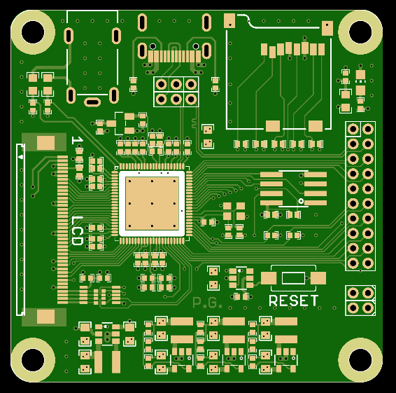
    Something on F1C100s by piotr_go
    PCB ordered, I hope it does not sleep ........ :)
    F1C200s (64MB) + LCD + AV + USB-C + uSD + SPI + I2C + I2S + UART ...
    Dimensions: 50x50mm
  • #14 18701938
    ArturAVS
    Moderator
    I can see that the work is progressing.
  • #15 18769722
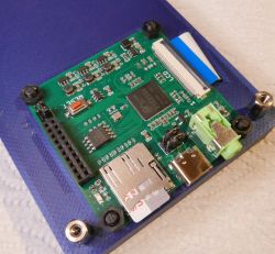
    piotr_go
    DIY electronics designer
    Something on F1C100s by piotr_go
    Tested, it works. Now it just stayed soft.
    Some simple OS would be handy to be able to load programs from the card.
    I'll take care of it tomorrow.
  • #17 18769854
    piotr_go
    DIY electronics designer
    Nah, and will I wait 3-5 seconds for it to take off? :)
    I'll try to write something myself. I'll see what comes out of this.
    I already have drivers for everything. Today I launched a new display with a capacitive touch.
  • #18 18770064
    blue_17
    Level 32  
    Maybe some interface for PS @ or USB to the keyboard because I am proud to play it :D I ask kindly :)
  • #19 18770120
    ArturAVS
    Moderator
    Pretty neat tile came out.
  • #20 18770405
    piotr_go
    DIY electronics designer
    blue_17 wrote:
    Maybe some interface for PS @ or USB to the keyboard

    I forgot about the USB completely, I don't have this driver. It will probably come off a bit because the USB chapter has only 3 pages in PDF.
    ... unless I connect via UART using this .
  • ADVERTISEMENT
  • #21 19037159
    bronek999
    Level 2  
    Hello

    I'm interested in this ARM SOC.
    I have digital photo frame and I want to make display connected to PC.
    In this time there is original firmware stored in SPI flash. Type I don't know, mark from package is removed.
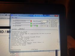
    Connection to JTAG pins TCK,TMS,TDI,TDO was succesfull, j-link GDB server found 0x07926F0F (ARM9) device.

    How can I continue?
    I have no idea. I need only LCD display interface and serial interface (USB or UART).
    Today I bought Lichee Nano with linux firmware and 40pin LCD for testing.
    My display is 50pin, there is 2more power sources enabled by GPIO of F1C100s.

    Where to start if I want to develope standalone application? (no linux)
    I'm working with STM32, gcc+eclipse, but there is no support for Allwinner devices....


    Something on F1C100s by piotr_go Something on F1C100s by piotr_go
  • #22 19037216
    piotr_go
    DIY electronics designer
    Firmware can be uploaded via USB. No jtag required.
    Software for uploading is called "sunxi-fel".
    In the makefile from first post there is a command "make boot" or "make flash".
    To make this work flash need to be empty or disconnected.
    You can lift dataflash HOLD pin and connect to goround when needed.
  • #23 19039132
    bronek999
    Level 2  
    Piotr thanks for answer.
    Now I have connected this board by USB. sunxi-fel knows download spiflash for backup.
    So next question:
    Is here some hello world project? SDK or IDE for develpoment?
  • #24 19039228
    piotr_go
    DIY electronics designer
    bronek999 wrote:
    Is here some hello world project?

    First post.
  • #25 19116432
    bronek999
    Level 2  
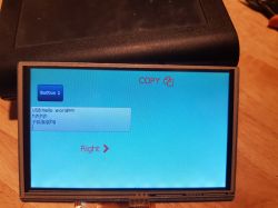
    My project is pure hardware C application with no OS,no XBOOT, no RTT.
    Only hardware drived by f1c100s driver library.
    USB (CDC or HID) added. Graphics widgets by lgvl_io

    Something on F1C100s by piotr_go

    result is


  • #26 19118524
    piotr_go
    DIY electronics designer
    bronek999 wrote:


    Thumb up.
  • #27 20925661
    macka4gg
    Level 5  
    I know, this topic is a bit old, but it so happens that the manufacturer decided to put this system in the display, or rather the control panel (because I communicate with the control unit only via the serial port and GCODE commands) of the Creality Ender 3 S1 pro printer, and I would like to use it to capture the video signal on any universal interface, e.g. HDMI or VGA. Would it be possible to do something like this? If so, how? I will add that the control panel has an SD card slot used to update the "firmware", or really probably software, because I read somewhere that the microcontroller has Linux installed.
  • #28 20926052
    piotr_go
    DIY electronics designer
    macka4gg wrote:
    I would like to use it to capture a video signal on any universal interface, e.g. HDMI or VGA. Would it be possible to do something like this?

    The system only has CSI (camera) and CVBS (composite video) inputs. I doubt either is output to the PCB.
  • #29 20926802
    macka4gg
    Level 5  
    Would it be possible to somehow capture the signal from this composite input and display it on the screen?
  • #30 20926914
    piotr_go
    DIY electronics designer
    If you find a description of the CVBS registers and write the appropriate driver, why not.

Topic summary

The discussion revolves around the F1C100s, a Chinese System on Chip (SoC) featuring an ARM9 processor, 32MB DDR1 RAM, and various interfaces including LCD, camera input, and audio codec. Users are experimenting with the Lichee Pi Nano tile, exploring applications such as SDR receivers and HMI displays. The conversation includes technical insights on interfacing LCDs, using external ADCs for better performance, and developing software without a full operating system. There are mentions of the F1C200s model, which offers enhanced capabilities. Participants share progress on hardware and software development, including successful implementations of USB, DMA, and graphics widgets.
Summary generated by the language model.
ADVERTISEMENT