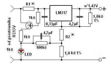
Here you have a diagram:

You choose R1 so that half of the nominal current on this resistor gives about 0.5V. For 2100mAh, the nominal current is 210mA, so R1 = 5 to 10?.
You choose R2 so that the output is n times 1.42V, where n = the number of charged cells connected in series.
The charger works in such a way that after switching on the LED diode lights up continuously, and when charging is finished, the diode flashes - initially fast, then slower and then goes out.
The system should be powered from a source with a voltage higher by approx. 4 - 5V over 1.42V times the number of cells, so for 4 cells it should be approx. 10V.
The charger works unattended, and its final charging voltage does not allow the cells to be overcharged.


