The Dorji Company
has made available to users of forum elektroda.pl free of charge 20pcs DRF4463F modules based on Silicon Labs
Si4463.
This article presents the results of external tests performed for elektroda.pl.

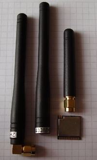
As you can see modules have very small dimensions, but they have a lot of functionality.
The module board is covered with a solid solder mask and the description of the pin makes it easy to test.
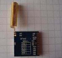
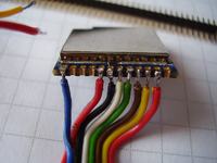
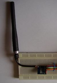
The input/output signals can be connected via goldpin strip or soldering wires directly, this helps working in test conditions such as bareboard.
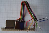
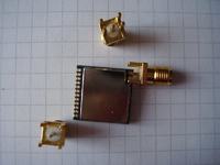
Connecting the antenna can be performed directly on the board or using a short length of the coaxial wire, this should prevent damage to the test conditions.
The module is generating the preamble and sync word, and has extensive configurable parameters such as transmission power, modulation (eg. OOK, 2(G)FSK, 4(G)FSK, GMSK),
bit rate (up to 1000Kb/s).
The transmission can be realized using the built-in 64B FIFO (a separate transmit and receive buffer), mechanism of formation of frames and data fields.
For the data fields in the frame can be computed checksums, frame can be fixed or variable length.
The module has a rich interrupt system allows signal errors, events, send/receive packet, fill/empty the FIFO etc.
The module also has the function of measuring temperature, the external voltage ,and battery condition.
The module communicates with the microcontroller using the SPI bus, built-in module functions allow you to significantly reduce the utilization of microcontroller during transmit and receive data.
You can configure the detection of a specific frame header (up to 4B), plus a logic bit mask can be used in the detection specified string in the header.
This allows the processor receives only the frames match with a specific pattern .
The module has a lot of configuration parameters, testing should start by installing the Wireless Development Suite (
WDS) Modules. Here is a brief description
Link.
After setting the program can generate a header file with the proper values for the module .
A simple test code to compile on the Atmel Studio and running on AVR microcontroller Atmel ATMEGA8A is available below.
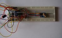
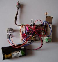
For the test has been used the base station and the mobile station.
The purpose of the base station is a regular polling the mobile stations, and sending data to the PC serial port 19200b/s.
The base station MCU is powered by 3.3V@8MHz.
The task of the mobile station is to respond to the calls of the base station and send current location received from the GPS via serial port 9600b/s.
The mobile station MCU is powered by 3V(two AA batteries)@4MHz.
Modules take current spot on to the current in the datashet.
The RF modules are connected to the SPI port of the microcontrollers,
nSEL module line is connected to the SS SPI line of the microcontroller.
Line SDN module line is connected to the microcontroller pin PB1 .
NIRQ module line is connected to the line INT0 ( PD2 ) of the microcontroller, but in the example code test microcontroller interrupt INT0 is not used .
PB0 microcotroller line is connected to the LED indicator coupled to ground through a resistor 220Ω .
Rx line USART of the base station can be used as input for debugging commands,
Tx line USART of the mobile station sends messages about the state of the program and also can be used for analysis.
The mobile station filters the GPS messages $GPGGA sending information about your location ,
also GPS time data is replaced with information about the level of the signal received from the base station and the package number.
Code should be considered as the ability to easily start with your experiments with the module.
Both the module and the processor allows much more functionality than was presented in the example code.
You should also refer to the sample code available on the manufacturer's website www.dorji.com
I encourage you to run some own tests with these modules, and present interesting results on the forum
it will be especially interesting for people that have so far worked with RF modules with direct modulation input.
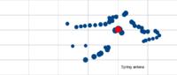
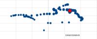
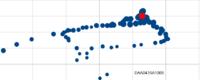
Depends on the antenna we get different transmission ranges,
coverage map below is for power ~5 mW and different antennas.
The red dot is the base station.
The blue points are places where transmission has been possible.
Dot size depends of signal strength.
Horizontal division is about 50m.
Spring antena:
DAA043SA064S:
DAA043SA100S
The following code examples using DRF4463F in Atmel Atmel Studio and AVR microcontroller ATMEGA8A.
DRF4463_base.zip
DRF4463_mobile.zip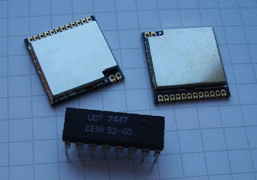


Comments