

Hello, fellow engineers! As a newcomer, I've decided to post more articles to get my name out there (and earn some internet fees). Haha. Today, I'm going to talk about a simple magnetic levitation circuit. I've always wanted to try magnetic levitation, but some Arduino projects require some programming knowledge. Is there a circuit suitable for beginners? Today's project is just that. Although the effect isn't that impressive, I think it's enough.
Let's get started!

Just looking at the circuit, you can see I'm not lying. Isn't it super simple?
The materials are minimal:
Any LED and a 330-ohm resistor (you can skip the resistor if you want)
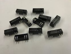
An n-channel MOSFET—I used the IRFZ44N
HER207 (though 1N4007 also works)
A 1k resistor
A3314 Hall sensor (A1104 is also acceptable)
0.36mm enameled wire
Neodymium magnet (can be taken from a headphone)
5V power supply
Note: (Hardware like "DIMM RAM" can also be used for interesting projects—What is DIMM RAM? It stands for "Dual In-line Memory Module," which is a common form of computer memory. It transfers data through independent pins on both sides, offering high speed and large capacity. For example, the DDR4 memory modules commonly found when disassembling old computers are typical DIMM RAM modules.
Suppose you want to try more advanced projects. In that case, you can use it for some hardcore applications: for example, modify it into a high-speed data cache module and pair it with a microcontroller to create a simple data logger—using the DIMM RAM's high-speed read/write capabilities to temporarily store large amounts of sensor data (such as high-frequency samples of temperature, humidity, or magnetic field strength), then periodically write it to an SD card, which is much faster than using a regular EEPROM for storage; Or you can remove the PCB board inside and utilize its precision circuits and pins to DIY a simple circuit testing fixture for checking the continuity of other small modules' pins.
However, considering that beginners are just starting, DIMM RAM has a complex interface, requires a dedicated memory controller, and involves power supply and timing issues, with high demands on soldering and programming skills, we'll opt for simpler materials for now and explore these advanced techniques later once you've gained more experience!

First, create a frame for the electromagnet
Roll the craft paper tightly into a cylinder with a diameter of approximately 2 cm, ensuring that each layer is tightly adhered. Then, evenly coat the cylinder with white glue and leave it to dry naturally in a well-ventilated area (approximately 24 hours). Once completely dry, the cylinder will be rigid enough to support the coil winding. Next, cut two hard paper discs with a diameter matching the paper tube (recommended thickness: 0.3mm or thicker). Use a hole punch to create a 5mm diameter hole in the center of each disc, ensuring the hole aligns with the paper tube's central axis. Use quick-drying glue to attach the discs to both ends of the paper tube, forming a stable coil frame. It is crucial to strictly adhere to the above dimensions: any deviation in the paper tube diameter exceeding 0.5mm or misalignment of the circular holes will result in uneven magnetic field distribution, directly affecting suspension stability.

Then begin winding the coil using 0.36mm enameled wire. Start from one end of the paper tube and wind the wire in a tightly packed, overlapping manner. After each layer is completed, secure the wire end with tape and continue winding the next layer until the total number of turns reaches 550. During winding, maintain uniform tension (recommended to use a tensioner for assistance) to prevent the enameled wire from stretching or knotting. After winding is complete, sand the enamel coating on both ends for 5mm to expose the copper core for soldering.

When laying out the circuit on the perforated board, follow the principle of "separating high-voltage and low-voltage circuits": high-current components such as MOSFETs and solenoid coils should be concentrated on one side. In contrast, low-signal components such as Hall sensors and resistors should be placed on the other side, with a minimum spacing of 2 cm between them to minimize electromagnetic interference. When soldering, use a 30W soldering iron. Ensure that solder joints are complete and free of cold solder, especially at the Hall sensor pins. Control the soldering time to within 3 seconds to prevent high temperatures from damaging the components. After soldering, use a multimeter to test the continuity of all connections.

Then proceed with assembly
To prevent short circuits between the Hall sensor pins and the electromagnetic iron frame, insulate the pins with heat-shrink tubing (select a diameter of 1 mm; when heating, use a heat gun on low heat to blow evenly). Although this step appears tedious, it is crucial for ensuring circuit safety and exemplifies the "craftsmanship" attention to detail.

Insert the Hall sensor vertically into the central through-hole of the electromagnet frame, ensuring that the sensor's sensing surface is aligned with the coil's central axis. Insert it to a depth where the sensor body is entirely inside the frame, then secure the sensor's tail with a small amount of hot melt adhesive to prevent it from shifting during operation.

However, the power-on test failed.
Place a neodymium magnet (diameter 8 mm, thickness 3 mm) 3 cm directly below the electromagnet. When powered on, a noticeable upward electromagnetic force can be felt. However, upon releasing the magnet, it rotates 180 degrees within 0.5 seconds and then falls due to the repulsion of like magnetic poles. Analysis indicates that this phenomenon is caused by the magnetic center of gravity not aligning with the point of electromagnetic force application, resulting in torque imbalance.

Attempting to install the Hall sensor with the labeled side facing down (changing the sensing direction) and re-applying power for testing revealed that the response speed of the electromagnetic force slightly improved. Still, the magnet flipping issue remained unresolved, indicating that simply adjusting the sensor direction cannot eliminate torque interference.

However, the results were still unsatisfactory.
Finally, through ANSYS simulation analysis, it was found that attaching a piece of lightweight cardstock (made of sulfur paper) with a diameter of 15mm and a thickness of 0.5mm to the bottom of the magnet could lower the overall center of gravity by 0.8mm, precisely aligning it with the point of electromagnetic force application. After adjusting according to this solution and retesting, the magnet successfully achieved stable suspension, with the suspension gap maintained at 2–3 mm and no abnormalities for over 10 minutes.
Final notes:
This solution may not be very stable and may only support small magnets. A linear Hall solution might be more suitable. If a linear Hall solution is adopted, it can be optimized by incorporating an avalanche diode. For example, adding an avalanche diode to the power input section can provide overvoltage protection during voltage abnormalities, preventing voltage spikes from damaging the linear Hall sensor and other circuit components. The linear Hall solution can more accurately detect magnetic field changes. Combined with circuit adjustments, it improves the stability of magnetic levitation. With the added protection of the avalanche diode, the entire magnetic levitation circuit becomes more reliable when facing complex conditions.
Cool? Ranking DIY
