Since I bought a 3d printer I have been looking for a program to design parts. I needed a program that was reasonably easy to use and allowed me to draw relatively simple parts, „non-artistic”.
After testing various things, I came across
Link . For me the bomb. Online application, easy to use, tutorials on yt.
On the aforementioned website you can share your designs or use the ready-made products provided.
Creating details for 3D printing is as easy here as in the cartoon „The Enchanted Pencil”
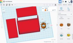
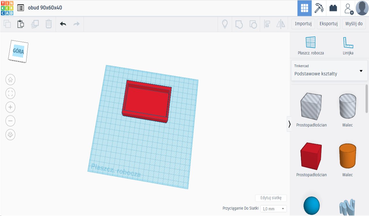
Drawing case with external dimensions 90x60x40mm, walls 2mm, front and back panels 1mm thick.
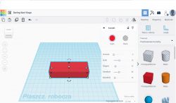
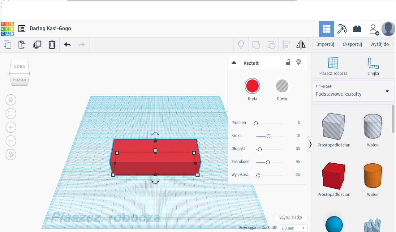
We start by selecting the Cuboid from the menu on the right and placing it in the centre of the working plane. We then set its dimensions to 90x60x20.
This will be the outer dimension of one half of the casing. This can be done on the object menu or by editing the dimensions that appear on the dimension lines.
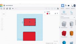
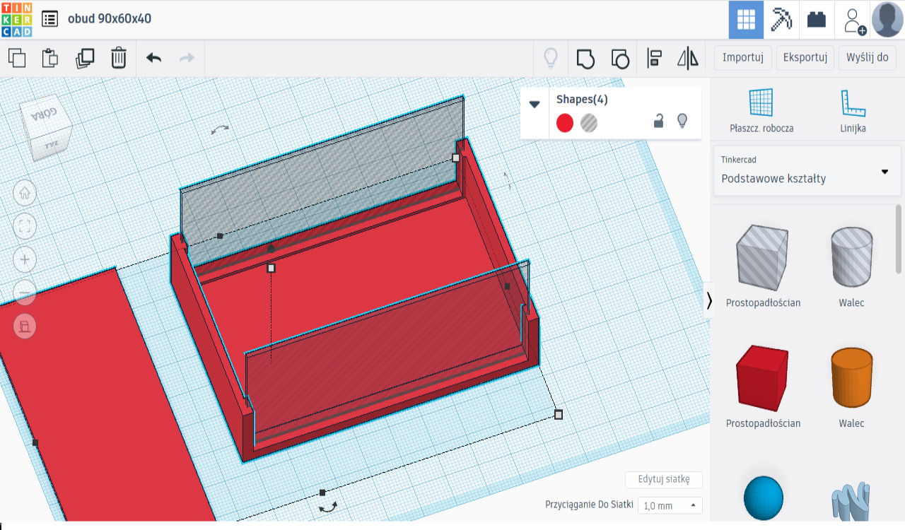
We click LPM on this object and ctrl ctrl v, move the copy to the side and set its dimensions.
These will be the internal dimensions of the housing half after taking into account the assumed wall thickness i.e. our Hole should be 86mm and raised above the working plane by 2mm using the black triangle.
This can only be raised in front, side view by rotating the working plane using the cube in the top left corner.
The second dimension is 50mm which will allow the front panels to be fixed.
The method of removing unnecessary material using the „Hole” object from the „Solid” object is the basic way of obtaining shapes other than the basic ones on the right-hand side of the menu.
Slide one element over the other fairly centrally, select both elements and choose the Align function. Set the Top view and click the central black circles which will align the 2 elements centrally in the horizontal plane.
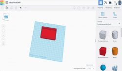
We just select the smaller shape and convert it to a Hole from the Shape menu.
Then select the 2 elements again and choose the Group function which will merge the Object and Hole to give a new shape.
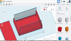
Next, select the Cube Hole again and set its dimensions to 84x70 and raise it 3mm above the working plane. Overlap the elements, centre and group.
The rim for fixing the panels will extend above the plane by 1mm and we will make a 1mm groove in it.
We select the Cuboid once again and set its dimensions as for the front panel i.e. 86x40x1mm which should give the Shape in the vertical plane. We copy and position as the front and back panels should be positioned in the enclosure.
Attracting the grid and zooming in on the image should be enough for accurate alignment but if that didn't work we use the Align tool.
We change the Grid Attraction in the bottom right corner of the work plane.
Change both Shapes to Holes, select the whole thing, Group.
The grooves for attaching the panels should show up.
Once again, create a Shape with the same dimensions as the panel, but place the element horizontally. This will be the front or back panel. Copy x2 if there will be different holes in them. Alternatively, the previously created Hole x1 can be copied, transformed into a Shape and arranged on the work plane. Make the necessary holes in the panels. The Ruler function can help with this.
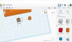
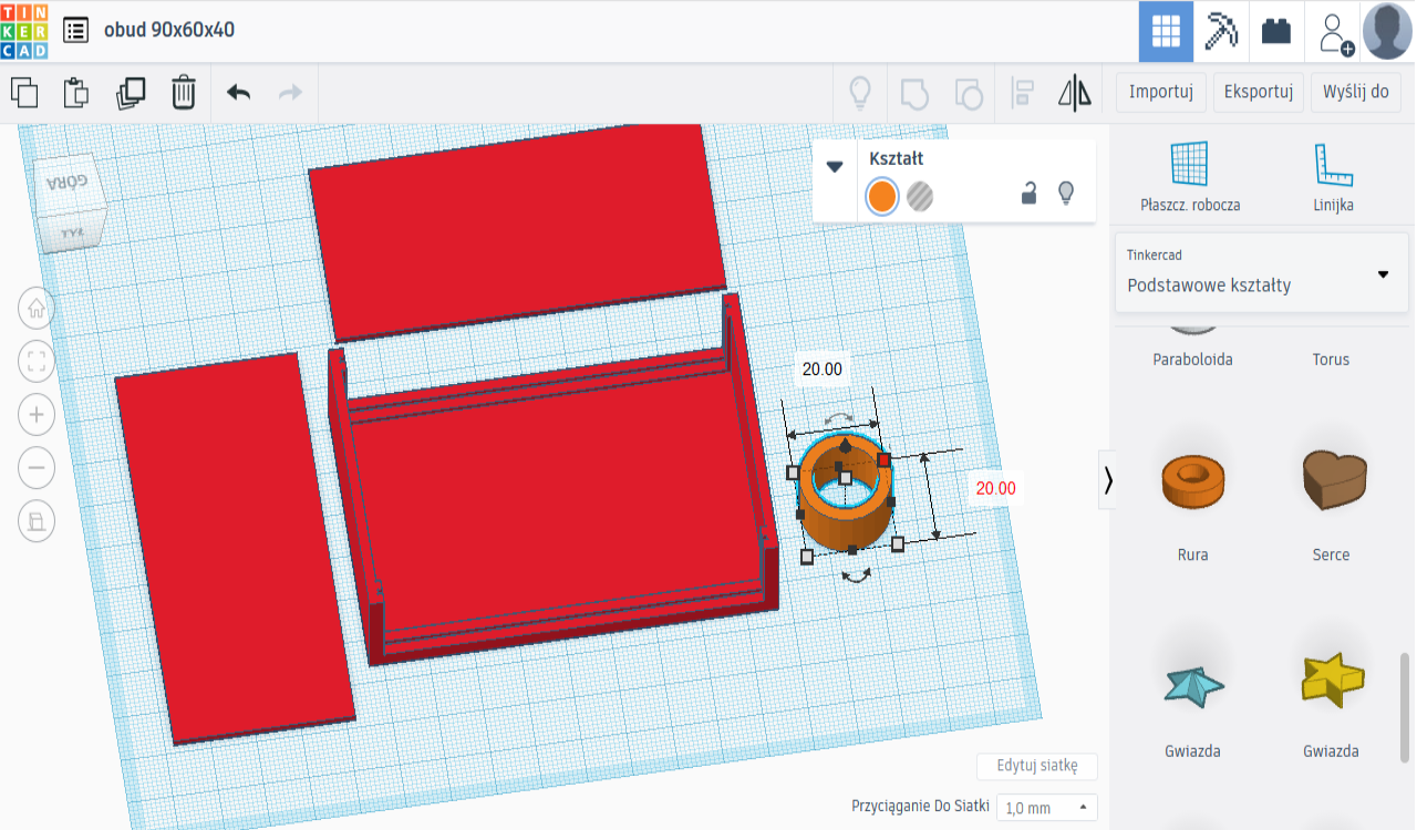
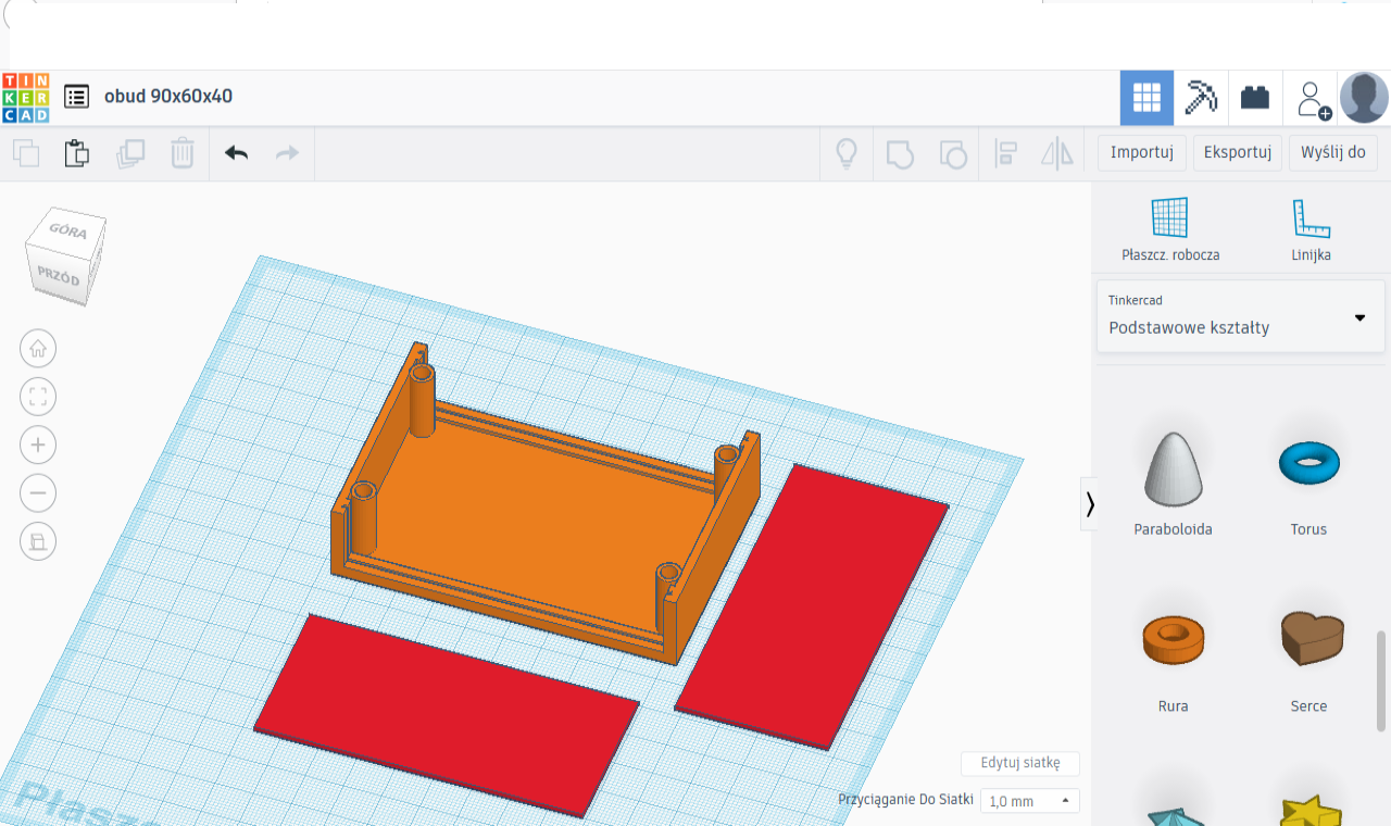
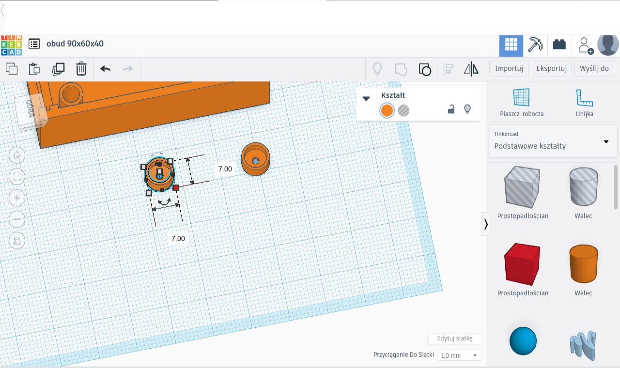
Now it is time to make the sleeves for the fixing screws using the Pipe Shape from the Basic Shapes menu.
Outside dimensions 6mm, inside 3mm, height 21mm. Copy x3, position symmetrically at the edges, recess 1mm. Elements to be printed as a whole are not sufficiently close - they must be recessed into each other.
Holes in the housing plane can be drilled or created with the Cylinder Shape in Hole mode with a diameter like the desired hole.

You can also think about footers in which the nuts and bolt heads will hide. Felt or rubber washers can be glued into them to mask the nuts and bolts.
Example dimensions outside 7mm, wall 1mm, hole 2mm, height 4mm.
The feet will be to be fixed loosely, like washers, using nuts and bolts.
There is no obstacle to making hexagonal recesses in the plane of the case and fitting both heads and nuts there.
For fixing the circuit board, you can design oblong cuboids with drilled holes into which the circuit board can be screwed and then glued to the housing. the board will be removable.
There are as many possibilities as there are ideas.
Click on the Export tab, select .stl and half the housing is ready to print!
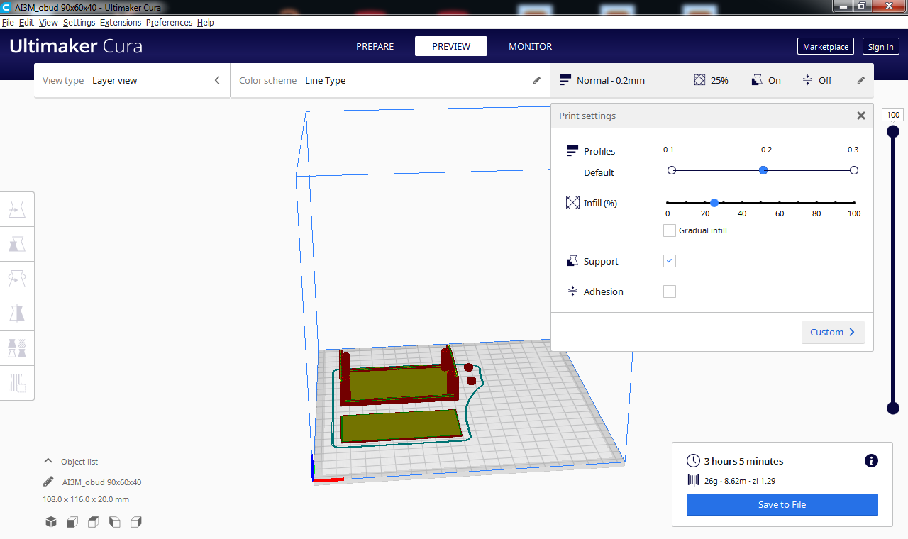
Open the file in a slicer, e.g. Cura, and see that....
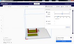
Time to print half of the casing 3h05min, weight 26g, with Normal quality and 25% fill.Approximate material cost with PLA filament price 50zl for 1kg is 1,29zl.
Isn't this the Enchanted Pencil of the 21st century?


Comments
Interesting service. It looks very simple and is worth considering, although I have mixed feelings. When I go to their site it refers me to a login form, so do I have to create an account with them... [Read more]
The main advantage of this programme is its simple operation. It only works online after an account has been created. I have not tried to edit there .stl-i produced by another program. You can of course... [Read more]
Certainly yes, only if you are going to develop then a simple application will quickly "run out". Also for free and after registration you have for example Fusion 360. What is supposed to be simple is... [Read more]
I confirm. Very cool service. You can log in with your EAGLE account because it is the same company :) . I previously used (and still use SKETCHUP) but I liked this one better. I also make dedicated... [Read more]
I used to use Sketchup and constantly had problems with models - after loading the stl into the slicer there were always some holes somewhere. I switched to Fusion360 and it's fabulous. An intuitive tool... [Read more]
For more complex shapes and dimensioning, TinkerCAD is torturous. For more serious applications there is Fusion360. Tinkercad is more like a children's toy for a first contact with 3D modelling. [Read more]
Even simple things need to be designed in some kind of programme. This is enough to design, for example, a dedicated case. I would highly recommend it to anyone who doesn't want to bash their head into... [Read more]
I tried the crap, installed FreeCAD after five minutes and have been at it for over a year. I plan to get Fusion360 because it's good to be able to use different tools, other than that I'm aware of FreeCAD's... [Read more]
It looks like a program for children. All these programs together with FreeCAD are weak. If someone wants to design professionally and efficiently, only SpaceClaim from ANSYS. Together with the Algoryx... [Read more]
This is a $2000 commercial program, rather beyond the reach of the average electrode user. Free CAD programs are able to extract 100% of the capabilities from today's 3D printers. [Read more]
I recommend ONSHAPE - a free (non-commercial) online programme. It designs very similarly to solidworks so you can do all sorts of things, export to all popular formats. [Read more]
I love OpenSCAD . Contrary to popular belief, this program is trivial for enclosure design . http://edutechwiki.unige.ch/en/OpenScad_beginners_tutorial [Read more]
A very cool tool for quickly extracting bitmaps. [Read more]