
logo elektroda
logo elektroda
X
logo elektroda

DIP-encapsulated micro relays to be driven directly from the microcontroller/ESP pin?

p.kaczmarek2 2334 26

TL;DR

  • A V23100-V4 dual signal relay was tested as a tiny mechanical disconnect for microcontroller and ESP-controlled lines.
  • Its 500 Ω coil and built-in protection diode allow direct GPIO drive, avoiding an extra transistor in many DIY circuits.
  • The datasheet lists 1 A contact current, 200 V maximum voltage, 10 W switching power, 3.5 V operate, and 0.75 V release.
  • A 5 V test worked immediately, and an ESP32 at 3.3 V also closed the relay despite the 3.5 V operate rating.
  • The 3.3 V result stretches the specification, so production designs should still follow the manufacturer's limits.
Generated by the language model.
ADVERTISEMENT
This content has been translated flag-pl » flag-en View the original version here
📢 Listen (AI):
  • DIP-encapsulated micro relays to be driven directly from the microcontroller/ESP pin?
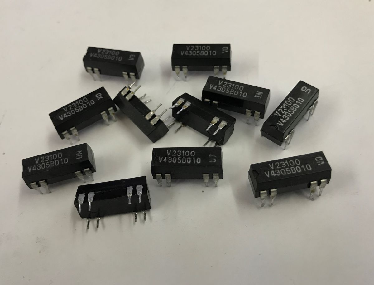
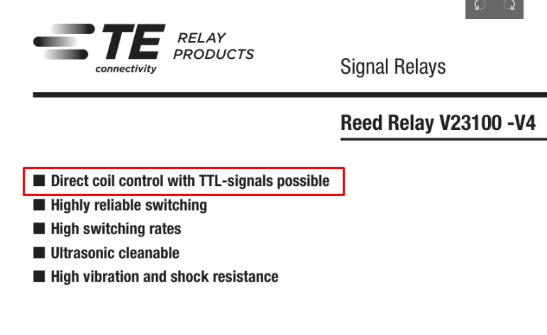
    Today a little tidbit I came across while developing one of my projects. I was looking for a simple way to mechanically disconnect microcontroller/ESP controlled lines, with a minimum of additional components. This is how I came across the very small V23100-V4 dual signal relays. Interestingly, the manufacturer explicitly emphasises in the documentation that the coil can be controlled directly by TTL signals, which is immediately appealing for projects with microcontrollers.
    DIP-encapsulated micro relays to be driven directly from the microcontroller/ESP pin?
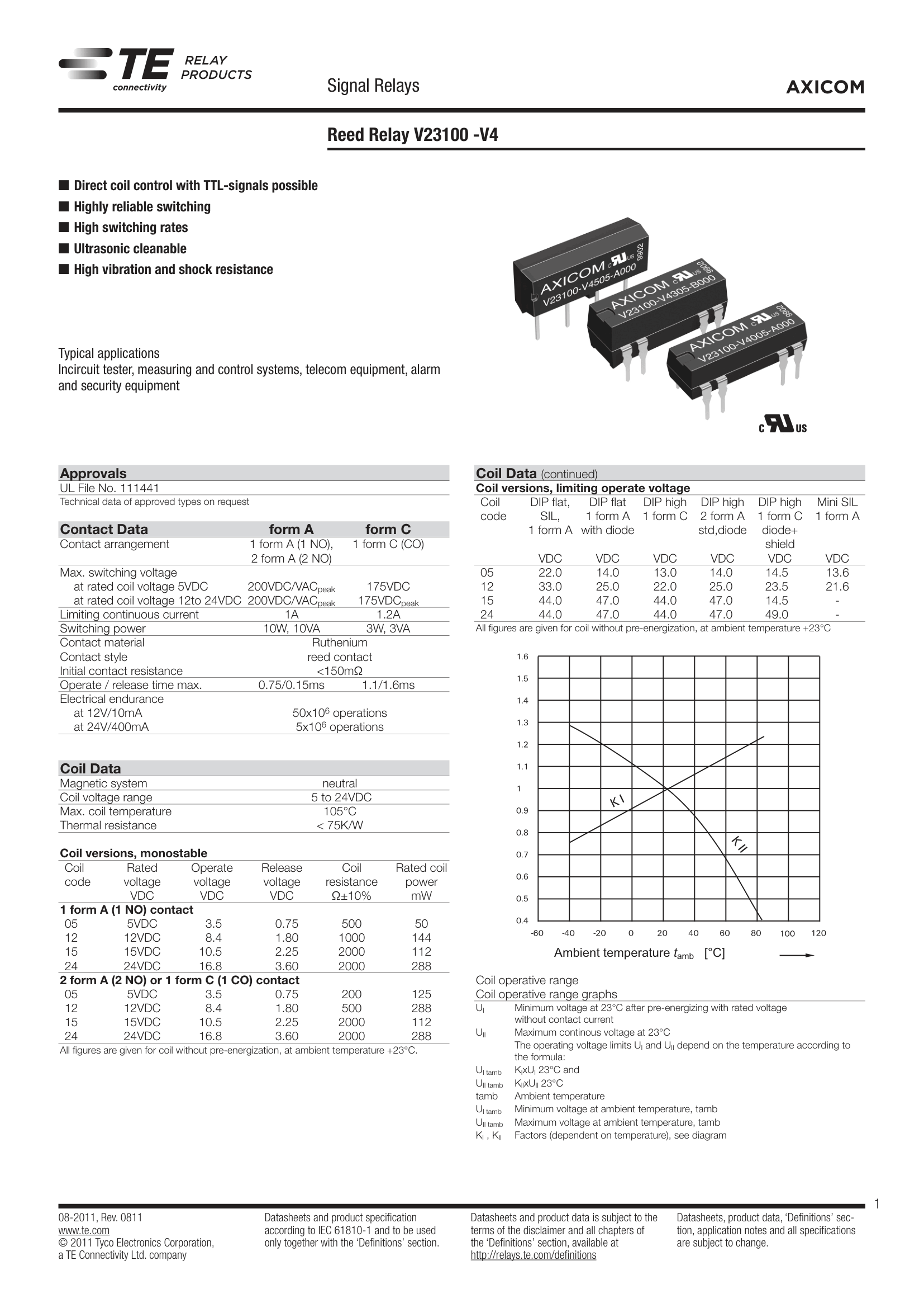
    Consider the parameters from the datasheet:
    - maximum contact current: up to 1 A
    - maximum voltage: up to 200 V
    - maximum switching power: 10 W
    For such a small relay, these are quite reasonable values - especially when it comes to signal applications or small loads. The coil parameters are also interesting:
    - coil resistance: ~500 Ω
    - coil power: ~50 mW
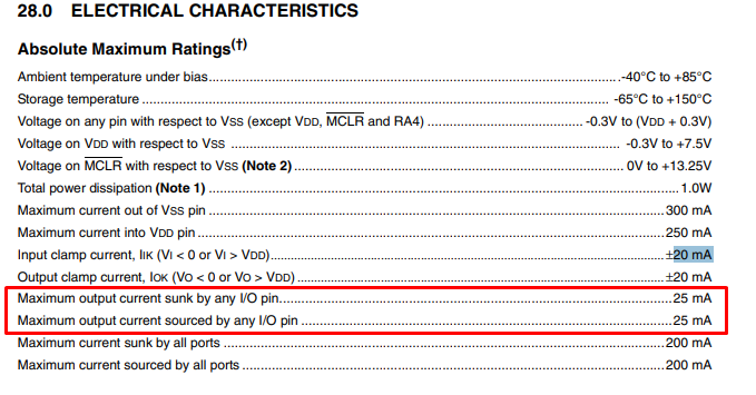
    This means that the control current is very low, which is precisely what makes direct control from the microcontroller output possible (at least in many cases). In practice, it is important to check how much current can be drawn from the GPIO. For example, for the PIC18F2550 it is 25 mA:
    DIP-encapsulated micro relays to be driven directly from the microcontroller/ESP pin?
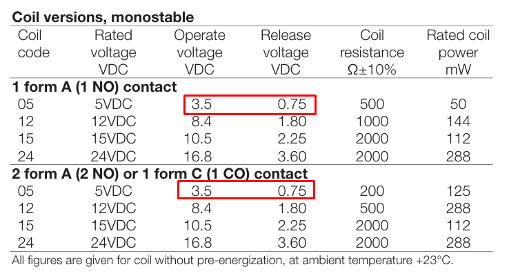
    Assuming a supply voltage of 5 V, about 10 mA will flow through the ~500 Ω coil. Well under the limit. Just what about lower voltages? According to the datasheet note:
    - closing voltage (operate): 3.5 V
    - opening voltage (release): 0.75 V
    DIP-encapsulated micro relays to be driven directly from the microcontroller/ESP pin?
    These values suggest that the relay is designed with low-voltage logic in mind. However, an interesting question arises: in practice, will it also work at even lower voltages than the declared 3.5 V? There is often some design reserve in such components, so I thought I would give it a go with ESP. DIY projects have their own rules, it's not mass production, so you can afford to do more. So it's time for testing.
    The whole thing has a standard DIP raster, so it fits on a contact board:
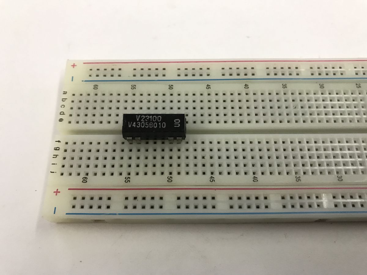
    DIP-encapsulated micro relays to be driven directly from the microcontroller/ESP pin?
    Leads - yes, there is already a protection diode inside in parallel to the coil, so you can't connect the coil in reverse either:
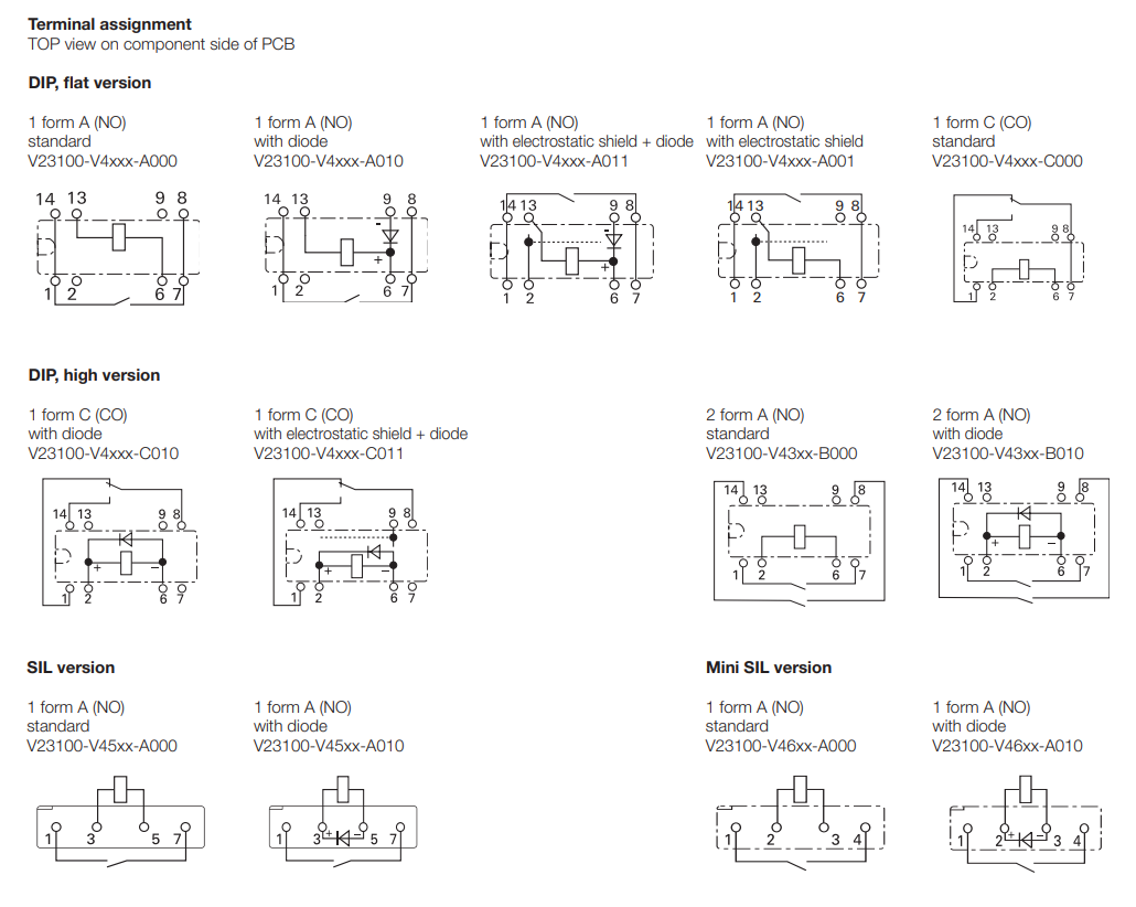
    DIP-encapsulated micro relays to be driven directly from the microcontroller/ESP pin?
    First test at 5 V - no surprise here rather, the whole thing works.
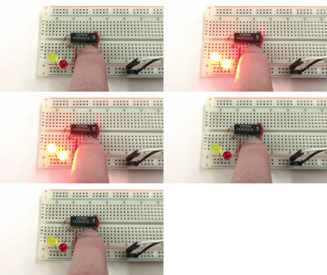
    DIP-encapsulated micro relays to be driven directly from the microcontroller/ESP pin?
    Second test - controlled from ESP32 at 3.3 V:
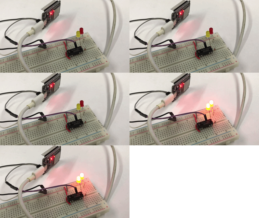
    Breadboard with a DIP relay and two LEDs, next to an ESP module with red indicator lights
    Here I've stretched the specification a bit, as the manufacturer announces the contacts close from 3.5 V rather than 3.3 V, but nevertheless the relay works too.
    In summary , this was an example of a small relay that in practice turns out to be much more 'friendly' to microcontrollers than the datasheet note alone might suggest. Thanks to the very low coil power consumption, it can in many cases be controlled directly from the GPIO, without an additional transistor. Of course, in production applications it is better to stick to the manufacturer's specifications, but in DIY projects such a reserve of parameters can be very useful.
    Undoubtedly this was a rather beginner's topic, but I hope it may have interested someone.
    Have you used this type of relay in projects, and if so, for what?

    Cool? Ranking DIY
    Helpful post? Buy me a coffee.

    About Author
    p.kaczmarek2
    Moderator Smart Home
    Offline 
    p.kaczmarek2 wrote 14459 posts with rating 12468, helped 650 times. Been with us since 2014 year.
  • ADVERTISEMENT
  • #2 21887918
    CosteC
    Level 39  
    Posts: 5251
    Help: 398
    Rate: 1622
    p.kaczmarek2 wrote:
    I've stretched the specification a bit here, as the manufacturer announces the contacts close from 3.5 V, not 3.3 V, but nevertheless the relay works too.

    The question is whether one is making something for art, for the desk. In such circumstances, one gets away with a great deal.
    For a product, especially one exposed to non-room temperatures, I would not risk controlling it with 3.3 V or even 3.5 V. The microcontroller output has its voltage drops, the coils have their spread which will cause occasional failures.

    On a completely different note: these are very good signal relays. They are by no means suitable for power applications (10 VA or 3 VA max) but for measurement applications as much as possible, especially in systems with low packing density.
  • #3 21887928
    p.kaczmarek2
    Moderator Smart Home
    Posts: 14459
    Help: 650
    Rate: 12468
    Right, but as I wrote in the next sentence - in production you should stick to these parameters and preferably with a margin, especially because if something goes wrong, a discrepancy of parameters on paper is always (according to common sense) the first sign of the designer's fault :D but let's not focus so much on 3.3 V, many microcontrollers operate on 5 V.
    And while we're on the subject of 3 V, I've also seen another curiosity recently. I've noticed that IoT manufacturers too have started to combine with relays on 3 V, but the kind for switching networks normally. For example, here:
    Template and firmware information for the generic Tuya EU WiFi Smart Plug with LN
    This is interesting to me because for years I have seen IoT devices based on a 5 V power supply, a relay for 5 V, and separately a 3.3 V LDO for the Wi-Fi module, and here suddenly they are already starting to simplify so much that directly the power supply gives 3.3 V and then the Wi-Fi module and the relay share power.
    Here the other one:
    [ZIGBEE] Zigbee 20A socket with energy measurement (Tuya TS011F_plug_3)
    Helpful post? Buy me a coffee.
  • ADVERTISEMENT
  • #4 21887952
    CosteC
    Level 39  
    Posts: 5251
    Help: 398
    Rate: 1622
    p.kaczmarek2 wrote:
    As long as we're talking about 3 V, I've also seen another curiosity recently. I've noticed that IoT manufacturers too have started to fiddle with 3 V relays, but ones for switching the grid normally.

    This makes sense... The 5 V relay is often the only receiver on 5 V so it makes the design more expensive and larger. And that it devours a lot of current is less of a problem than a separate power supply. The interference doesn't come from the relay coil in a good design anyway.
    I admire how bad the design has to be to opto-isolate relays, and I have seen such.
  • #5 21887969
    p.kaczmarek2
    Moderator Smart Home
    Posts: 14459
    Help: 650
    Rate: 12468
    In the IoT devices I have tested, I am unlikely to have seen opto-isolation in such an application, and we have shown a bit of these devices on the forum. Here's a dedicated search engine (each result leads to a separate Electrode topic):
    https://openbekeniot.github.io/webapp/devicesList.html

    Well, unless you consider industrial equipment, here too there are separate power lines in general:
    [YT] ESP32-S3-Relay-6CH six relay controller - schematic, flashing, Home Assistant
    Helpful post? Buy me a coffee.
  • #6 21887991
    acctr
    Level 39  
    Posts: 4530
    Help: 389
    Rate: 1995
    p.kaczmarek2 wrote:
    the manufacturer explicitly emphasises in the documentation that the coil can be controlled directly by TTL signals

    Where exactly did he write about this? TTL levels are ranges from 0 to 0.8 V for the low state and 2.4 to 5 V for the high state. In the table with the DS of this relay, there is a range from 3.5 V so this is not TTL.
    Helpful post? Buy me a coffee.
  • #7 21888006
    p.kaczmarek2
    Moderator Smart Home
    Posts: 14459
    Help: 650
    Rate: 12468
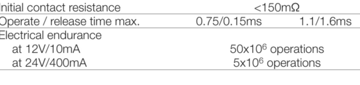
    I was referring to this passage from the catalogue note:
    DIP-encapsulated micro relays to be driven directly from the microcontroller/ESP pin?
    Helpful post? Buy me a coffee.
  • #8 21888043
    mkpl
    Level 37  
    Posts: 5648
    Help: 306
    Rate: 847
    It is possible to control this way but this approach has some limitations.
    Firstly, you have to be careful with the sum of the input currents relative to the supply (ground or power) pin.
    Controlling 'ground' also causes potential problems with ADC resolution. The common mode current is deposited on the single ground connection and directly affects the REF. 'Plus' control has the advantage of affecting the ADC less. Ground is great.
  • ADVERTISEMENT
  • #9 21888117
    acctr
    Level 39  
    Posts: 4530
    Help: 389
    Rate: 1995
    mkpl wrote:
    The "ground" control also causes potential problems with ADC resolution. The common mode current is deposited on the single ground connection and directly affects the REF.

    You can disconnect the relay for the duration of the measurement, the shortest time in the relay DS is 0.15 ms.
    Helpful post? Buy me a coffee.
  • #10 21888141
    CosteC
    Level 39  
    Posts: 5251
    Help: 398
    Rate: 1622
    mkpl wrote:
    The 'ground' control also causes potential problems with ADC resolution

    Will it drop from 10 bit to 9 bit? Not likely, as the problems could be with the accuracy of the ADC or rather with the reference voltage, as there will be offsets due to currents flowing in the ground precisely.
    But there's nothing to generalise, different microcontrollers have different things.

    Added after 23 [minutes]:

    p.kaczmarek2 wrote:
    industrial equipment

    Please, let's not call it "industrial". It didn't even stand next to it.
    But a great example. Can anyone explain what the opto-isolation of the relays is for? Why the complication?
  • #11 21888175
    acctr
    Level 39  
    Posts: 4530
    Help: 389
    Rate: 1995
    CosteC wrote:
    I marvel at how bad the design must be to opto-isolate relays, and I have seen such.

    CosteC wrote:
    Can anyone explain what the purpose of opto-isolating the relays is? What is this complication for?

    What is this project? Who is the author? Where have you seen it?
    Motivations can always be sensibly explained, either a technical reason or someone's whim.
    Helpful post? Buy me a coffee.
  • #12 21888214
    rezydent1
    Level 15  
    Posts: 270
    Help: 2
    Rate: 146
    My question is, what is the guaranteed number of switches. ?
  • #13 21888216
    Janusz_kk
    Level 39  
    Posts: 5700
    Help: 216
    Rate: 1431
    rezydent1 wrote:
    I have a question, what is the guaranteed number of switches. ?

    These are hermetic reed switches so they safely last for millions.
  • #15 21888254
    CosteC
    Level 39  
    Posts: 5251
    Help: 398
    Rate: 1622
    acctr wrote:
    CosteC wrote:
    I marvel at how bad the design must be to opto-isolate relays, and I have seen such.

    CosteC wrote:
    Can someone explain what the purpose of opto-isolating relays is? Why this complication?

    What is this project? Who is the author? Where have you seen it?
    Motivations can always be sensibly explained, either a technical reason or someone's whim.

    https://www.elektroda.pl/rtvforum/topic4144485.html
  • #16 21888322
    exlibris71
    Level 18  
    Posts: 202
    Help: 20
    Rate: 104
    >>21888254 Separating the ground (and not just the power supply) of the control part from the executive part can be convenient, e.g. with many such modules, thanks to opto-isolation, the connection point for these grounds can be in a common power supply and not in individual modules. The problem of interference carried by common ground paths has, by the way, already been mentioned by someone in this thread.
  • #17 21888361
    acctr
    Level 39  
    Posts: 4530
    Help: 389
    Rate: 1995
    CosteC wrote:
    acctr wrote:
    What is the project? Who is the author? Where have you seen it?
    Motivations can always be reasonably explained, either a technical reason or someone else's vision.

    https://www.elektroda.pl/rtvforum/topic4144485.html

    In the diagram you have the answer - the grounds are separate, they can be combined and separated, the relays can be fed from one power supply and the ESP from another. You will see what happens between the grounds of the separate power supplies on anything such as Fnirsi.
    Helpful post? Buy me a coffee.
  • #18 21888370
    CosteC
    Level 39  
    Posts: 5251
    Help: 398
    Rate: 1622
    acctr wrote:
    power the relays from one power supply and the ESP from another

    No... Everything flies from the power supply to J1, then there's 5V from it linear to 3V3 to the ESP. From 5V a small isolated inverter is used to make Relay-5V.
    The common ground of the relays and ESP.... What harm would it do? There are no analogue signals as such there.
    And how would these slow relay control waveforms be harmful? Assuming a sensible layout, of course.
    Anyway - the DC/DC converter ground is shared with the ESP anyway, so the relay currents flow in GND anyway, just processed by the DC/DC.

    And most importantly: how bad would the layout have to be for it to make a difference?
  • #19 21888535
    kris8888
    Level 40  
    Posts: 6785
    Help: 531
    Rate: 1866
    p.kaczmarek2 wrote:
    This means that the control current is very small, which is what allows direct control from the microcontroller output (at least in many cases).

    Control current is one thing, but I assume that a suppression diode must also be inserted in parallel to the relay coil. Will it be sufficient to protect the after all quite sensitive to overvoltage output of the microcontroller?
    Maybe this is also the reason why 99% of circuits use an intermediate transistor (or e.g. the ULN2003 circuit) to control the relay.
  • #20 21888574
    krzbor
    Level 29  
    Posts: 1735
    Help: 40
    Rate: 1046
    kris8888 wrote:
    Control current is one thing but I assume there must also be a suppression diode inserted in parallel with the relay coil.

    Have you looked at the internal schematics of the relays the Author has provided? Half of these circuits (relays) have an integrated diode.
  • ADVERTISEMENT
  • #21 21888598
    kris8888
    Level 40  
    Posts: 6785
    Help: 531
    Rate: 1866
    krzbor wrote:
    Author? Half of these circuits (relays) have a diode built in.

    Ok, that's not what I mean, because I'm assuming the diode has to be there, it doesn't matter anymore whether inside the relay or outside.

    The point is whether this is enough to effectively protect the microcontroller output. Most likely yes, although personally I have never designed my circuits in such a way that even a very sensitive relay could be controlled directly from the microcontroller output.
  • #22 21888633
    CosteC
    Level 39  
    Posts: 5251
    Help: 398
    Rate: 1622
    kris8888 wrote:
    Alongside the relay coil there must also be a suppression diode. Will it be sufficient to protect the after all rather surge-sensitive output of the microcontroller?

    Sufficient ... How bad does the design have to be to damage the microcontrollers GPIO with a diode?
    How would this supposedly happen if there is still a transistor?

    When driving directly from the GPIO, the pin potential can go out by the conduction voltage of the diode behind the power rails. Which can be a problem with some circuits.
  • #23 21888797
    kris8888
    Level 40  
    Posts: 6785
    Help: 531
    Rate: 1866
    And what about potential interference on an I/O line (or several lines) when the relay is switched on and off? I'm just asking because I've never tried to control the relay directly from the microcontroller output until now, although maybe it's time to finally test that too.
    Does it work stably?
    It might behave differently than, for example, switching ordinary LEDs on and off.
  • #24 21888823
    CosteC
    Level 39  
    Posts: 5251
    Help: 398
    Rate: 1622
    kris8888 wrote:
    what about potential interference on the I/O line (or multiple lines) when the relay is switched on and off

    If switching the relay alone is disrupting your system then it is a very badly designed system. It's just blowing current and slow waveforms.

    As for interference from load switching, that is a different and broad topic.
  • #25 21888838
    kris8888
    Level 40  
    Posts: 6785
    Help: 531
    Rate: 1866
    CosteC wrote:
    If switching the relay alone interferes with your system then it is a very badly designed system.

    I'm not saying that it interferes with me because I just haven't even tried such a direct control solution yet. In fact, I haven't even encountered it in finished devices so far either, perhaps only because of unsuitable relays. That's why I'm just asking about the possible experiences of others in this regard. I don't know what project the author of this topic is working on at the moment, maybe he can share his opinion on whether such relay control works reliably for him without causing harmful interference on the microcontroller lines.
  • #26 21892877
    VIGOR_PICTURES
    Level 21  
    Posts: 869
    Help: 20
    Rate: 146
    I have a question from ... Another side: is it possible to make a video with sound of how such small relays work?
  • #27 21892910
    p.kaczmarek2
    Moderator Smart Home
    Posts: 14459
    Help: 650
    Rate: 12468
    Here you have the source video (with audio, undeciphered):


    Helpful post? Buy me a coffee.
📢 Listen (AI):

FAQ

TL;DR: With a ~500 Ω coil, the relay draws about 10 mA at 5 V, and the author reports, "the relay works too" from an ESP32 at 3.3 V. This FAQ helps MCU and ESP builders decide when a V23100-V4 DIP relay can be driven directly from GPIO and when a transistor or more margin is safer. [#21887831]

Why it matters: Direct-GPIO relay drive can save parts and board space, but operating near the pull-in limit can create intermittent failures in finished products.

Option Coil supply / drive What the thread says Best fit
5 V relay from 5 V MCU GPIO 5 V / ~10 mA Works and stays below a PIC18F2550 25 mA pin limit Simple 5 V MCU designs
Same relay from ESP32 GPIO 3.3 V / below 3.5 V spec Tested working, but outside stated operate voltage DIY tests, not production
3.3 V relay with shared ESP/Wi‑Fi supply 3.3 V shared rail Used in some modern IoT plugs to simplify power design Compact IoT hardware

Key insight: Low coil power makes direct GPIO drive practical, but the thread’s strongest engineering advice is to keep design margin in production, especially across temperature, voltage drop, and part spread.

Quick Facts

  • V23100-V4 thread figures: max contact current 1 A, max voltage 200 V, max switching power 10 W. That makes it a small signal-switching part, not a power relay. [#21887831]
  • Coil data cited in the thread: ~500 Ω resistance and ~50 mW coil power. At 5 V, that implies about 10 mA coil current. [#21887831]
  • The posted operate/release figures are 3.5 V pull-in and 0.75 V release, so 3.3 V ESP32 drive is below the stated operate voltage even if a sample still actuates. [#21887831]
  • One participant warns that, in a finished product, microcontroller output voltage drop, coil tolerance spread, and non-room temperatures can cause occasional failures near the minimum drive point. [#21887918]
  • The relay package has standard DIP spacing and the coil includes an internal protection diode in parallel, so polarity matters during wiring. [#21887831]

How can I drive a V23100-V4 DIP dual signal relay directly from a microcontroller GPIO or an ESP32 pin without using an extra transistor?

You can drive it directly only if the GPIO can source or sink the coil current at the required voltage. 1. Check the coil resistance, shown here as ~500 Ω. 2. Compute current from the intended supply; at 5 V it is about 10 mA. 3. Compare that with the MCU pin limit and keep voltage margin above the stated 3.5 V operate level. The thread shows direct operation from 5 V and a working DIY test from 3.3 V ESP32, but that 3.3 V case sits outside the stated operate spec. [#21887831]

What current does the V23100-V4 relay coil draw at 5 V and how do I check whether a PIC18F2550 or ESP32 pin can supply it safely?

At 5 V, the ~500 Ω coil draws about 10 mA. Check safety by comparing that current with the GPIO limit of the controller. The thread gives 25 mA as the PIC18F2550 output-current figure, so 10 mA is comfortably below it. For an ESP32, the same method applies: calculate the coil current first, then confirm the pin can deliver it while still keeping enough output voltage for relay pull-in. Current limit alone is not enough if the output voltage sags near the relay’s minimum operate value. [#21887831]

Why does a V23100-V4 relay sometimes work from an ESP32 at 3.3 V even though the datasheet lists 3.5 V as the operate voltage?

It can work because a real sample may have some margin below the stated 3.5 V operate point. The author tested the relay from an ESP32 at 3.3 V and observed that it still actuated. That does not move the official pull-in specification; it only shows that this particular test setup and relay sample worked below the guaranteed value. Use that result as a DIY experiment, not as a guaranteed design rule for every unit, temperature, or supply condition. [#21887831]

What problems can appear when a relay is driven close to its minimum operate voltage in a finished product, especially across temperature and part tolerances?

You risk occasional failures to pull in. One participant explicitly warns against using 3.3 V or even 3.5 V in a product because the microcontroller output has voltage drop, coils have unit-to-unit spread, and non-room temperatures worsen margin. A bench test may pass, yet a production unit can miss actuations under colder, hotter, or lower-voltage conditions. That makes borderline drive acceptable for desk experiments, not for hardware that must switch reliably every time. [#21887918]

Which is better for small MCU-controlled switching tasks: a 5 V relay driven directly from a 5 V microcontroller or a 3.3 V relay shared with an ESP/Wi-Fi supply?

A 5 V relay on a 5 V MCU is the safer direct-drive choice when current and voltage margin both check out. A 3.3 V shared relay and logic rail can simplify IoT hardware because it removes a separate 5 V relay rail, and the thread notes that some modern Tuya Wi‑Fi and Zigbee devices already do this. Choose the shared 3.3 V approach when reducing cost, size, and power rails matters more than preserving wider actuation margin. [#21887928]

How do I wire a DIP relay with an internal flyback diode correctly, and what happens if I reverse the coil polarity?

Wire the coil with the correct polarity shown for the internal diode. The thread states that the diode is already connected in parallel with the coil, and the author notes that you cannot connect the coil in reverse. In practice, that means the relay has a defined positive and negative side instead of a fully interchangeable coil. The standard DIP spacing helps breadboard use, but the diode makes polarity checking mandatory before you apply 5 V or 3.3 V drive. [#21887831]

What does TTL control really mean for a relay coil, and why did the forum discussion question whether 3.5 V operate voltage qualifies as TTL-compatible?

In the thread, “TTL control” is questioned because a stated 3.5 V operate voltage does not align cleanly with classic TTL high-level expectations. One participant points out that TTL levels are ranges, with high starting at 2.4 V, so a relay that only guarantees pull-in from 3.5 V is not inherently TTL-compatible by that definition. The catalog note may use “TTL” loosely for logic-driven convenience, but the forum correctly separates marketing wording from guaranteed electrical thresholds. [#21887991]

What is a signal relay, and how is it different from a power relay when switching measurement lines or small loads?

A signal relay is for low-power paths, not for heavy loads. "Signal relay" is an electromechanical relay that switches measurement or low-level circuits, with small contact power limits and compact construction. In this thread, it is described as suitable for measurement applications and low packing density systems, but not for true power switching. One reply stresses that these parts are “very good signal relays” yet “by no means suitable for power applications,” citing limits such as 10 VA or 3 VA max in that context. [#21887918]

What is opto-isolation in relay modules, and why would a designer isolate the control side from the relay side grounds?

Opto-isolation separates the control interface from the relay side so grounds and supplies can remain separate or be joined deliberately. "Opto-isolation" is galvanic signal separation that transfers control through an optocoupler, keeping the control side electrically distinct from the relay-side supply and ground, which can reduce shared-ground interaction and simplify modular wiring. In the thread, the practical reason given is flexibility: the relay section can run from one supply, the ESP from another, and the grounds can be combined or separated as needed. [#21888361]

Why can low-side relay control through ground affect ADC accuracy or reference stability in some microcontroller designs?

Low-side control can shift the local ground reference seen by the analog section. One reply warns that relay current returning through the common ground path creates voltage drops on that shared connection, and those drops directly affect REF and ADC accuracy. The thread does not claim a fixed loss such as “10-bit to 9-bit,” but it clearly identifies ground-current-induced offsets as the mechanism. This matters most when analog measurements and relay drive share the same narrow ground path. [#21888043]

How can I reduce ADC measurement errors when relay coil current shares the same ground path as the analog circuitry?

Disconnect the relay during the measurement window or avoid sharing the sensitive ground path. One participant suggests turning the relay off for the measurement itself and notes a shortest datasheet time of 0.15 ms in that context. That gives you a clear timing strategy: switch, settle, measure, then restore the relay state if needed. Separate grounding or supply partitioning can also help, but the thread’s concrete mitigation is temporary relay disconnection during ADC sampling. [#21888117]

What is the guaranteed switching lifetime of these hermetic reed-style micro relays, and how does load type affect the number of operations?

The thread does not provide a numeric guaranteed lifetime, but one participant says these hermetic reed switches “safely last for millions.” That means the discussion only supports a qualitative answer, not a guaranteed cycle count. Load still matters because switching light signal paths stresses contacts less than harder electrical loads. If you need a guaranteed lifetime for a product, the thread points you toward the exact datasheet endurance entry rather than treating “millions” as a universal specification. [#21888216]

Why are some modern Tuya WiFi or Zigbee smart plugs moving from 5 V relay supplies to 3.3 V relay and logic supplies in the same design?

They do it to simplify the power architecture and reduce cost and size. The thread notes that older IoT designs often used a 5 V supply for the relay plus a separate 3.3 V LDO for Wi‑Fi, while newer products increasingly share a 3.3 V rail between the radio and relay. A reply says this makes sense because the 5 V relay is often the only 5 V load, so keeping that separate rail increases expense and board area more than it helps. [#21887952]

What should I look for in a datasheet when choosing a DIP micro relay for direct GPIO control, including coil resistance, coil power, operate voltage, and contact ratings?

Check four numbers first: coil resistance, coil power, operate voltage, and contact limits. In this thread, the useful figures are ~500 Ω coil resistance, ~50 mW coil power, 3.5 V operate voltage, 0.75 V release voltage, 1 A maximum contact current, 200 V maximum voltage, and 10 W maximum switching power. Also verify package style, here a standard DIP format, and whether the coil already includes a protection diode because that changes polarity handling. Those values tell you both drive feasibility and switching scope. [#21887831]

How do separate grounds and separate supplies for ESP and relay sections change noise behavior in multi-relay boards such as ESP32 relay controllers?

Separate grounds and supplies let you control where relay current returns and where noise can couple. The thread explains that, with isolation and split supplies, the relay section can run from one source and the ESP from another, with grounds either combined or left separate. That can reduce interference carried by common ground paths across multiple modules. A later reply challenges whether such separation matters much without analog signals, so the benefit is strongest when ground-current routing or system modularity is the real design constraint. [#21888322]
Generated by the language model.
ADVERTISEMENT