
logo elektroda
logo elektroda
X
logo elektroda

How a racing set is built - steering wheel and pedals for USB/Playstation and PS/2

p.kaczmarek2 1188 3

TL;DR

  • The MX-V9 Vibration steering wheel and PS/2 pedals are torn down to inspect how PlayStation/PC racing controls are built.
  • The wheel uses a linear potentiometer for steering deflection, while vibration comes from unbalanced-weight motors and the pedals use a spring plus potentiometer.
  • The steering sensor is a B-type 20 kΩ linear potentiometer, and the wheel includes a PlayStation/USB switch.
  • Much of the board sits under an unknown 'black dot' IC, so the rest of the electronics remains opaque.
  • The simple button-and-ADC design should be easy to rewire under a PIC with enough ADC channels and input pins.
Generated by the language model.
ADVERTISEMENT
This content has been translated flag-pl » flag-en View the original version here
📢 Listen (AI):
  • How a racing set is built - steering wheel and pedals for USB/Playstation and PS/2
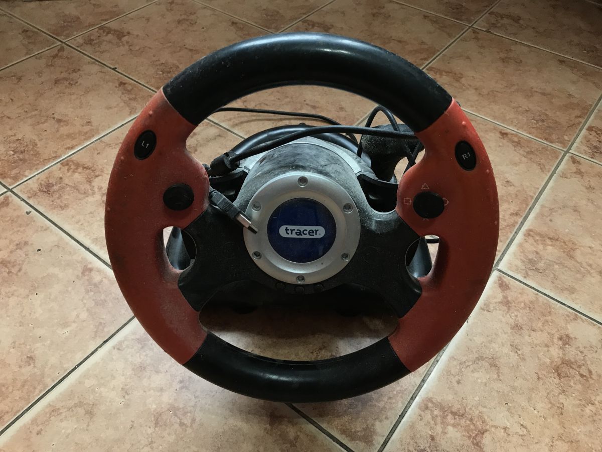
    I recently presented the running of the PIC16LF1659 as an HID keyboard or mouse controller . A gamepad or joystick can also be realised in a similar way, it just remains to determine how to handle the buttons and axes. This is a great opportunity to take a look inside two products that I've had set aside in the attic for a while.

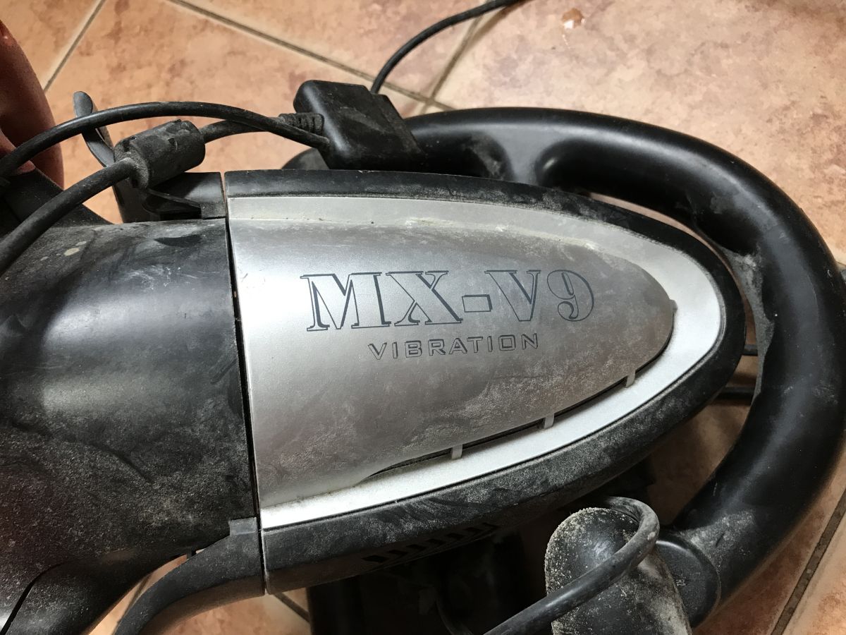
    The first piece of hardware to be showcased is the MX-V9 Vibration steering wheel, which works with either a PlayStation console or a PC via USB. As the name suggests, it is equipped with an additional feedback system via vibration, the mechanism of which we will also get to know.
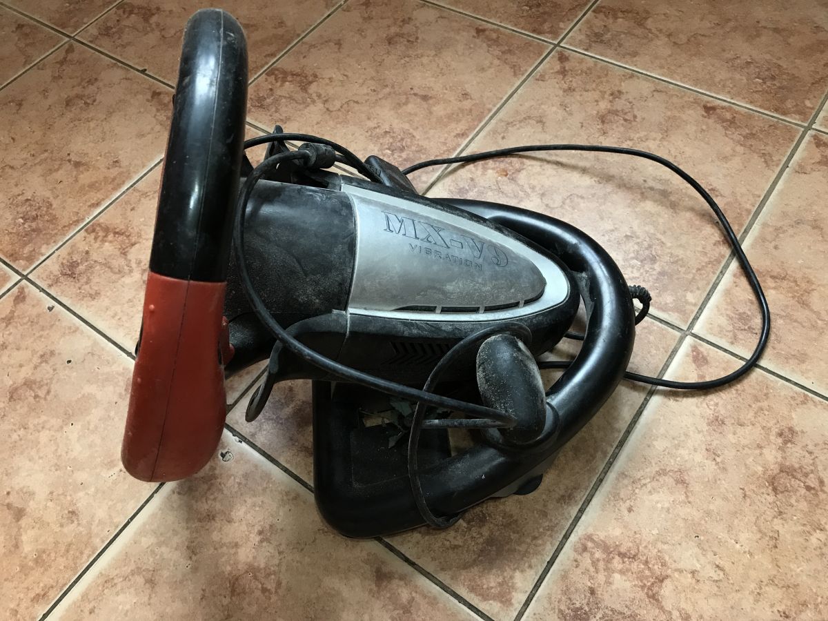
    How a racing set is built - steering wheel and pedals for USB/Playstation and PS/2 How a racing set is built - steering wheel and pedals for USB/Playstation and PS/2 How a racing set is built - steering wheel and pedals for USB/Playstation and PS/2
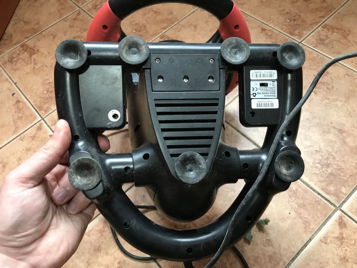
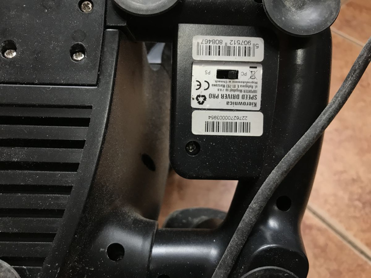
    Importer - Megabyte, manufacture in China. There is a Playstation/PC switch on the bottom.
    How a racing set is built - steering wheel and pedals for USB/Playstation and PS/2
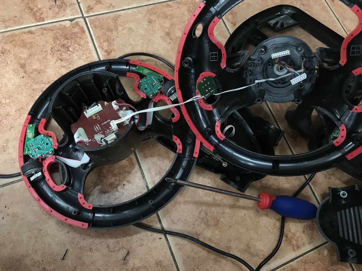
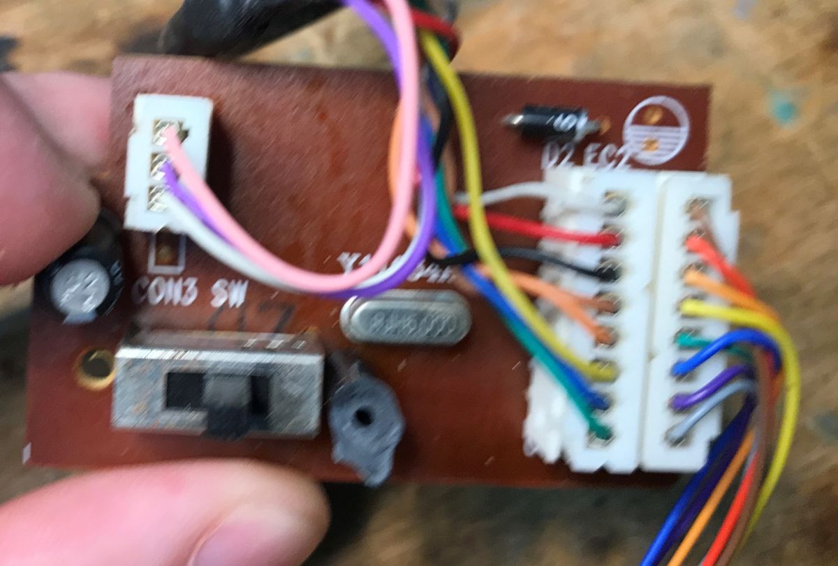
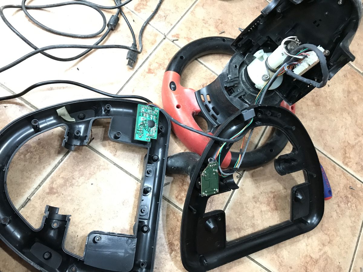
    The whole thing is held together by countless screws. You can tell by the PCB inside that the hardware is quite old. I was surprised that the separate modules are on plugs, probably this is from before the cost cutting. You can also immediately see how the steering wheel deflection is measured - it's just a potentiometer.
    How a racing set is built - steering wheel and pedals for USB/Playstation and PS/2 How a racing set is built - steering wheel and pedals for USB/Playstation and PS/2
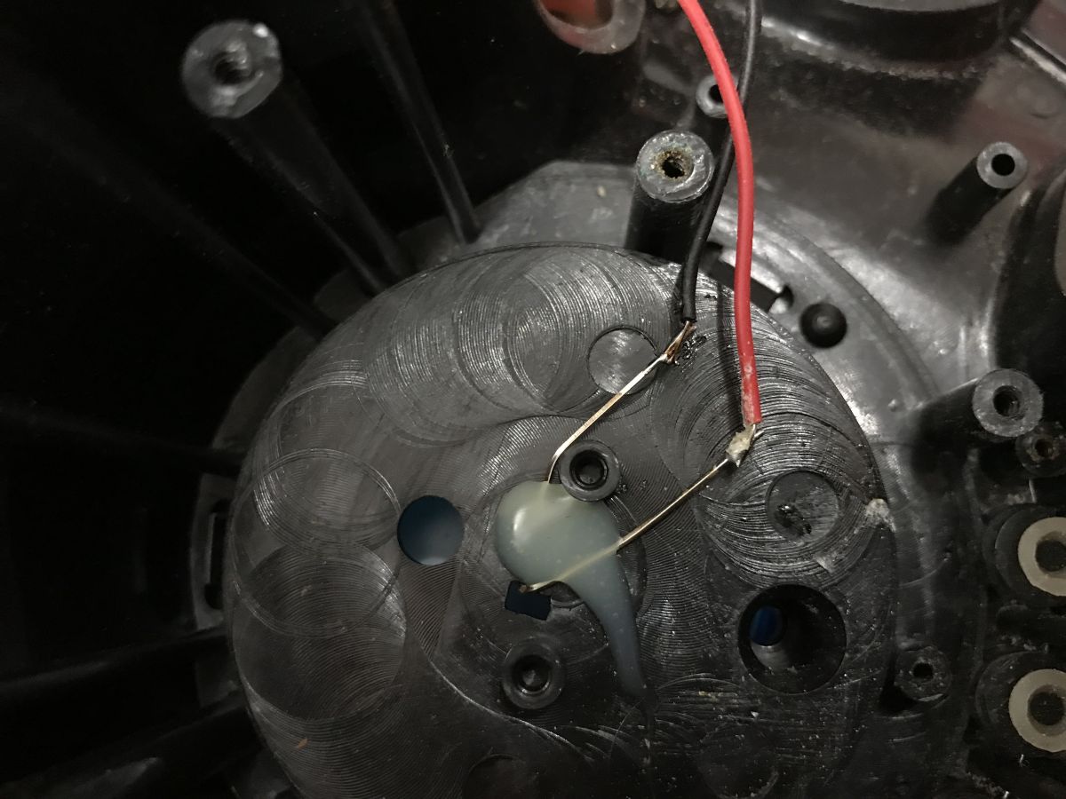
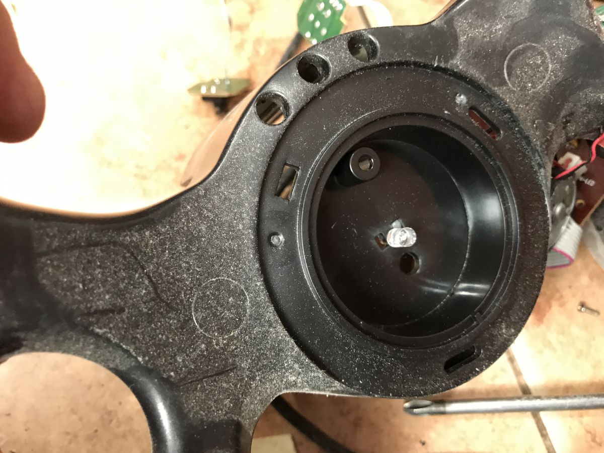
    The LED is mounted via hot glue:
    How a racing set is built - steering wheel and pedals for USB/Playstation and PS/2 How a racing set is built - steering wheel and pedals for USB/Playstation and PS/2
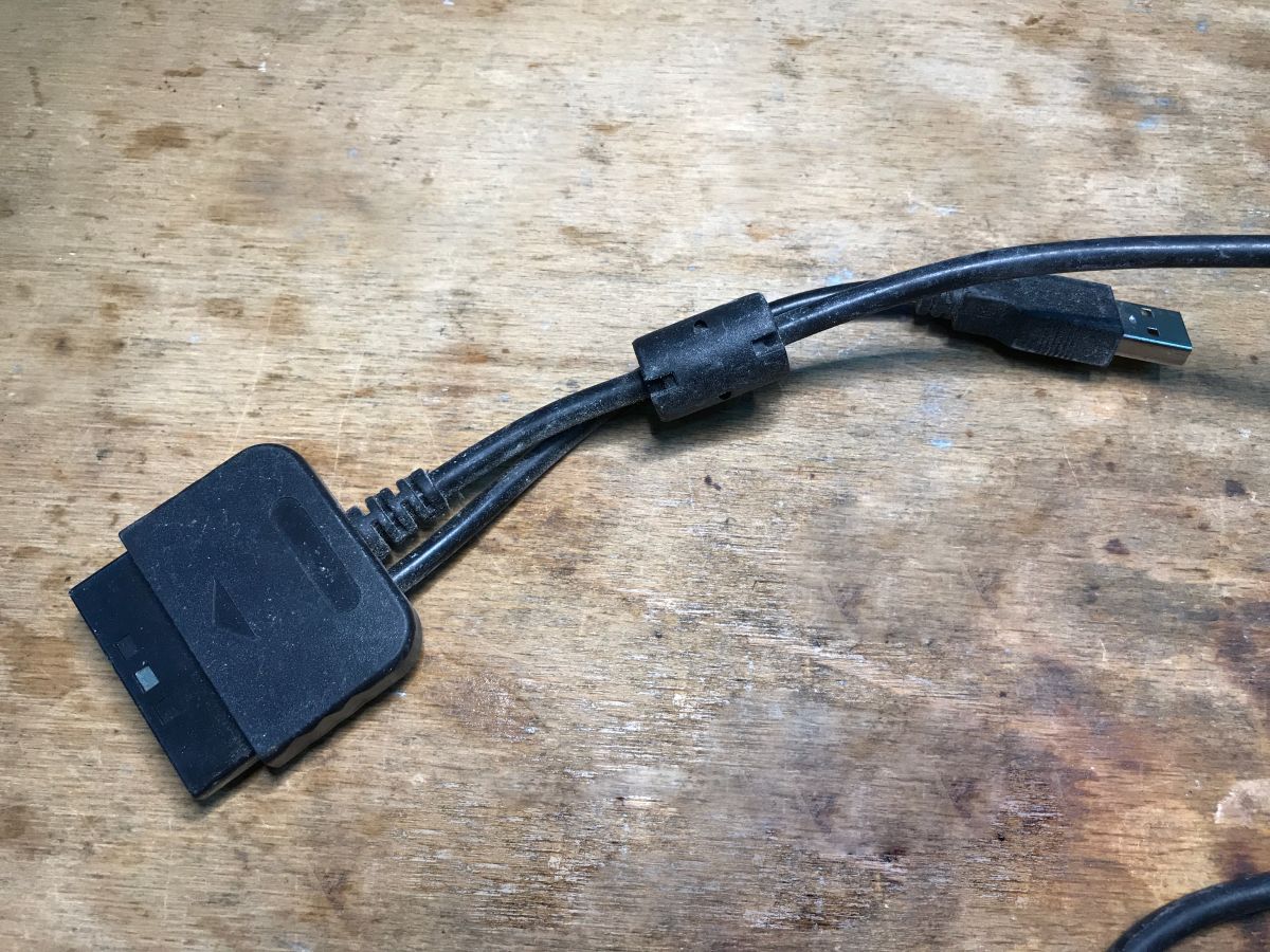
    Here's another cable mentioned - Playstation or USB:
    How a racing set is built - steering wheel and pedals for USB/Playstation and PS/2
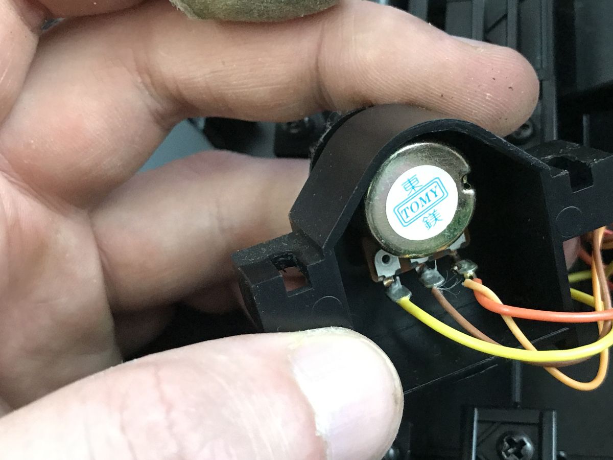
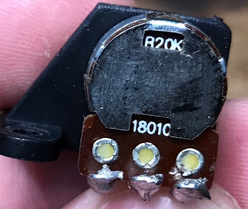
    As for this potentiometer, it is linear, 20 kΩ. The letter B stands for linear. Type A - logarithmic - is also popular, e.g. for audio, but it wouldn't make sense here.
    How a racing set is built - steering wheel and pedals for USB/Playstation and PS/2
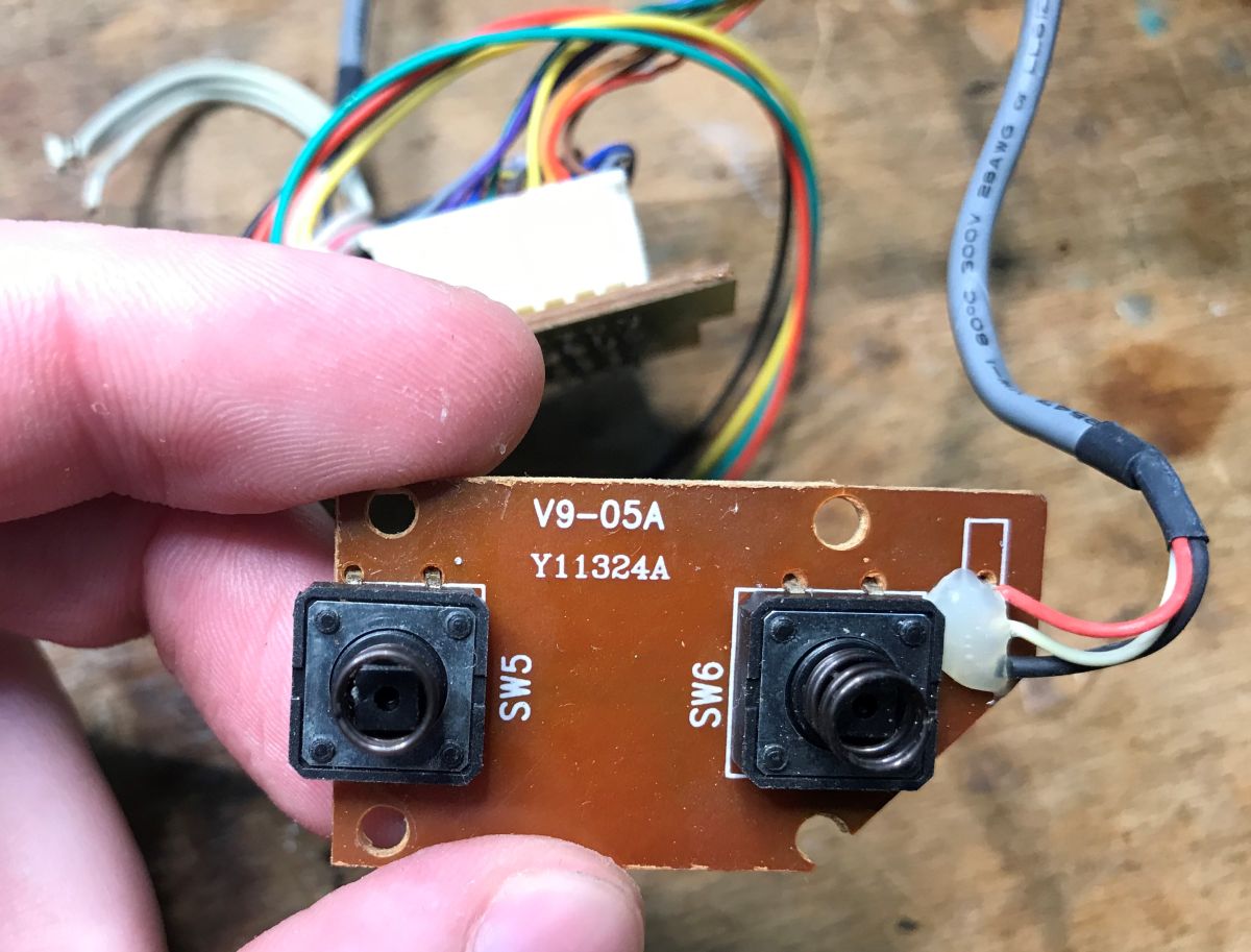
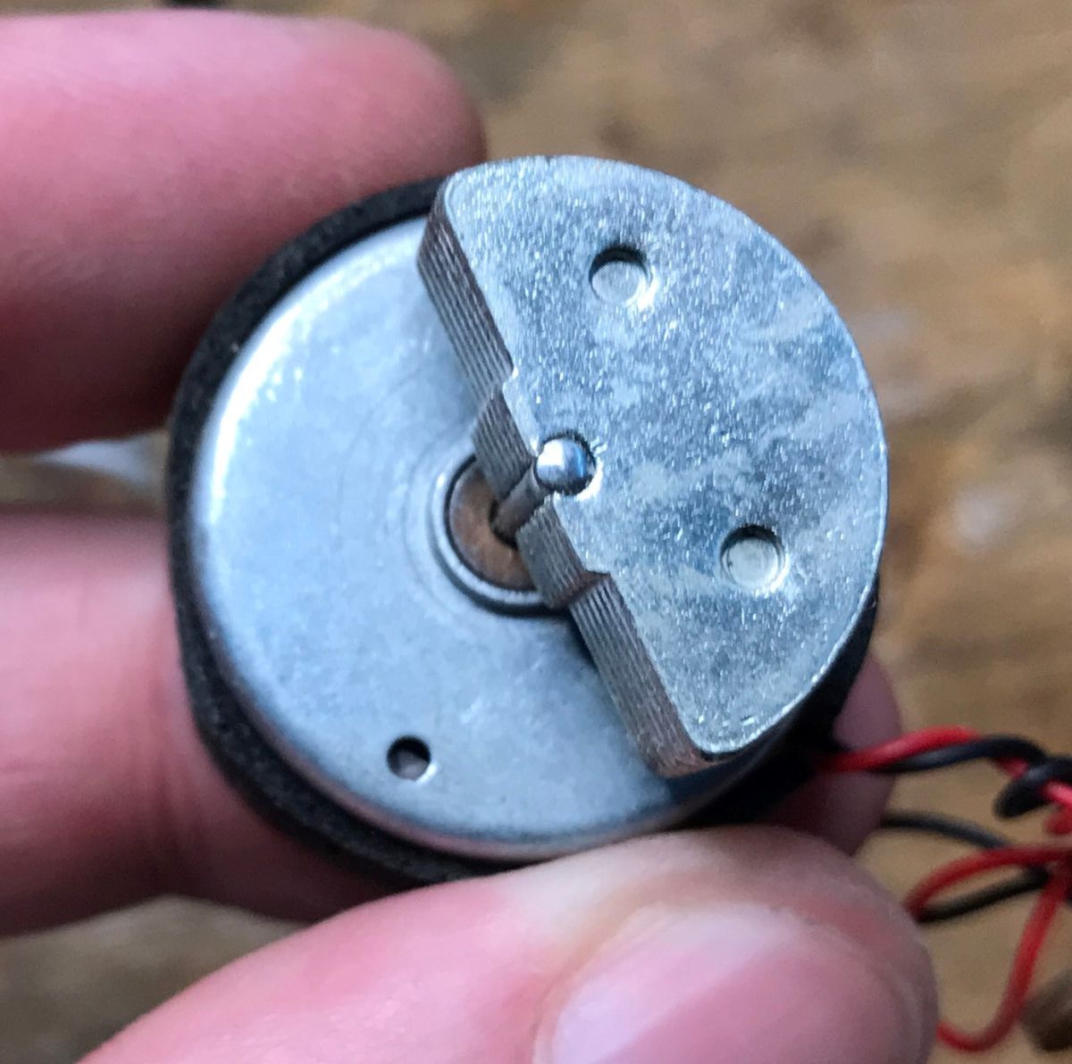
    Now for the vibration issue - these are created by motors with unbalanced weights.
    How a racing set is built - steering wheel and pedals for USB/Playstation and PS/2
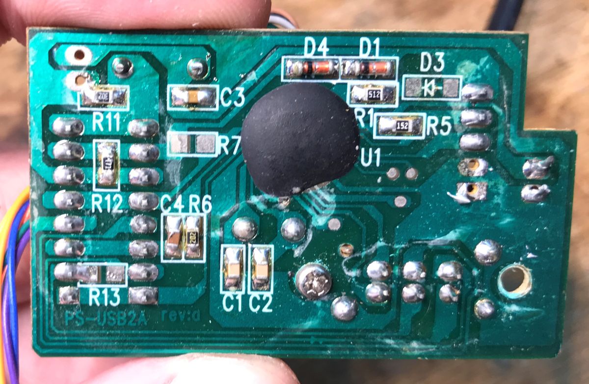
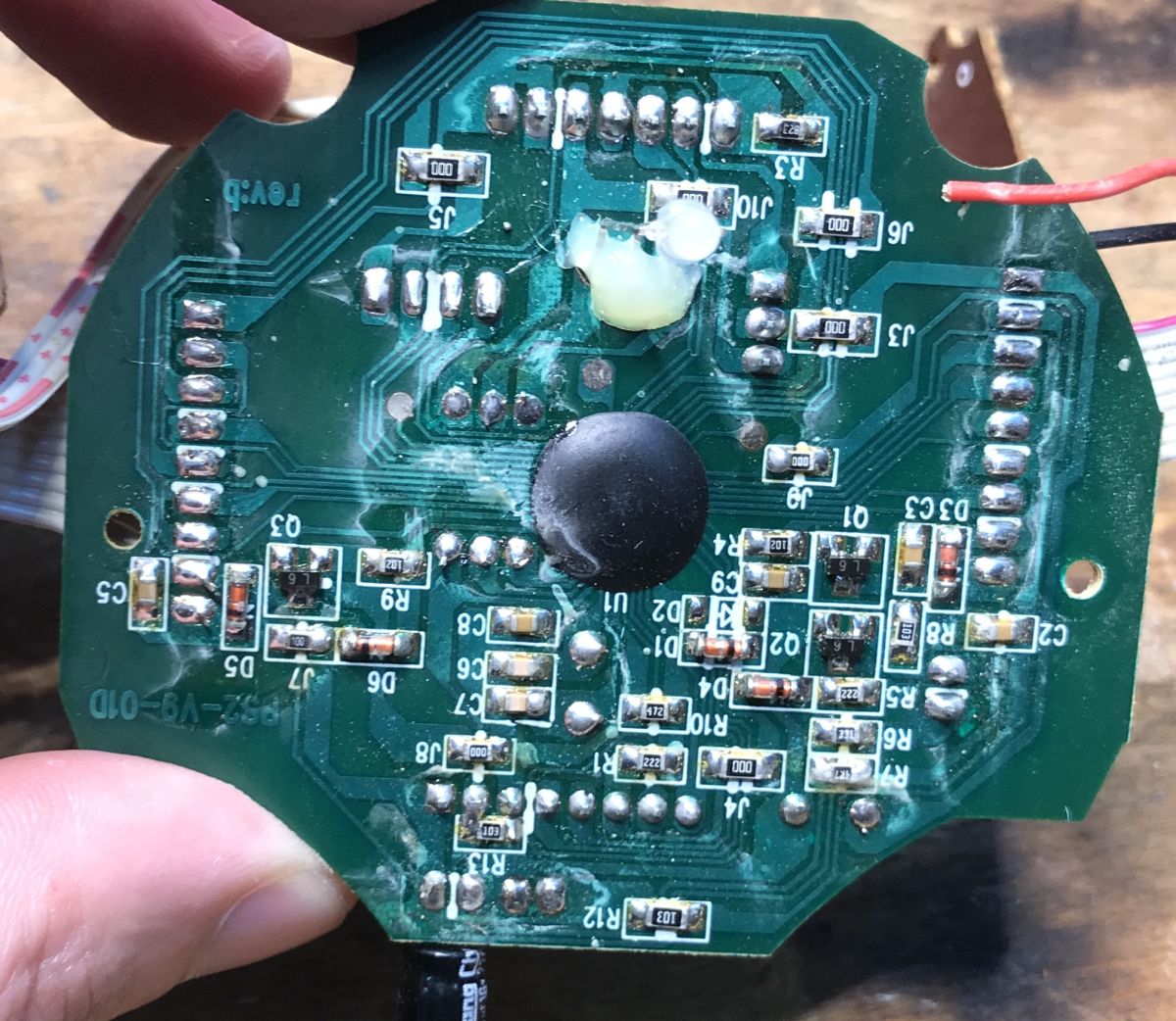
    Unfortunately the rest is less interesting, there is the famous "black dot" on the board, it is impossible to know what circuit it is:
    How a racing set is built - steering wheel and pedals for USB/Playstation and PS/2 How a racing set is built - steering wheel and pedals for USB/Playstation and PS/2
    How a racing set is built - steering wheel and pedals for USB/Playstation and PS/2 How a racing set is built - steering wheel and pedals for USB/Playstation and PS/2 How a racing set is built - steering wheel and pedals for USB/Playstation and PS/2
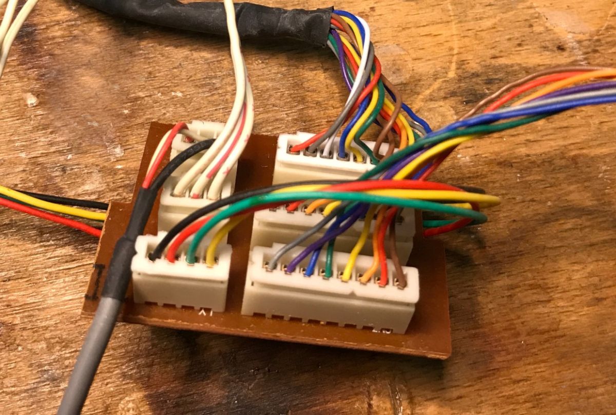
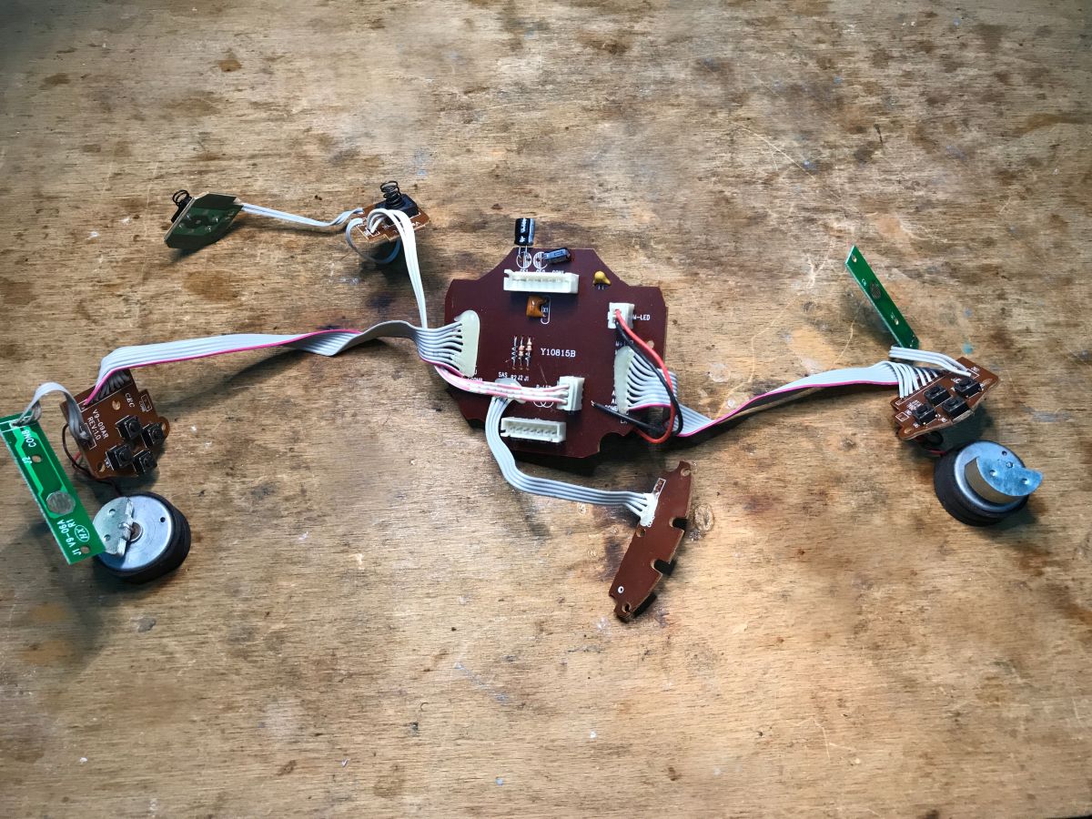
    All the electronics from inside:
    How a racing set is built - steering wheel and pedals for USB/Playstation and PS/2 All electronics from inside


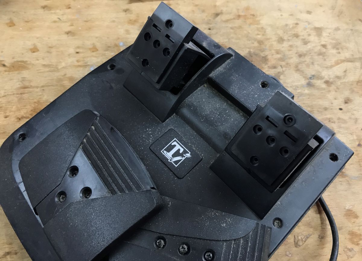
    Now the second part of the presentation - PS/2 pedals.
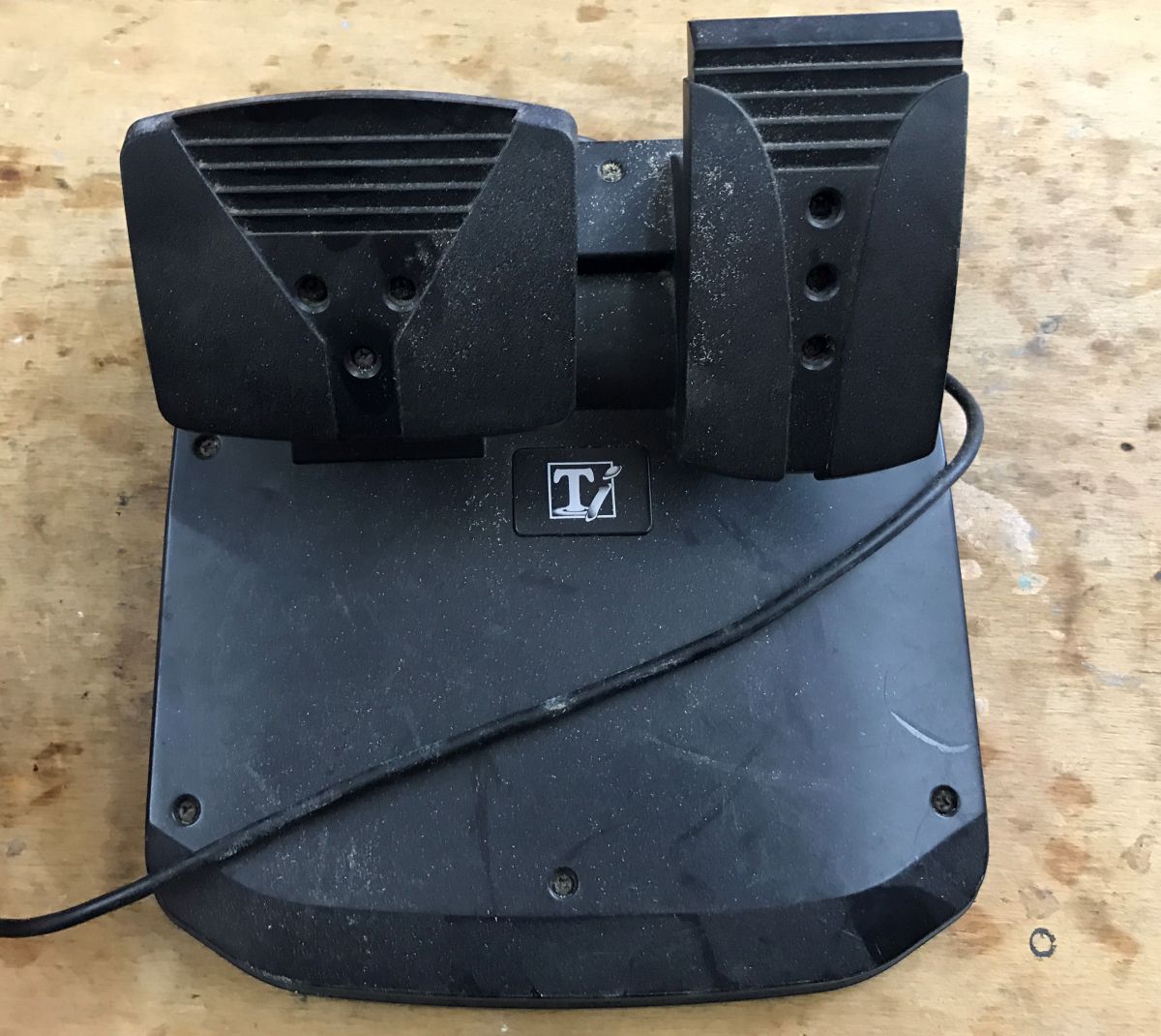
    How a racing set is built - steering wheel and pedals for USB/Playstation and PS/2
    Will the situation be different here? What measures the level of throttle depression?
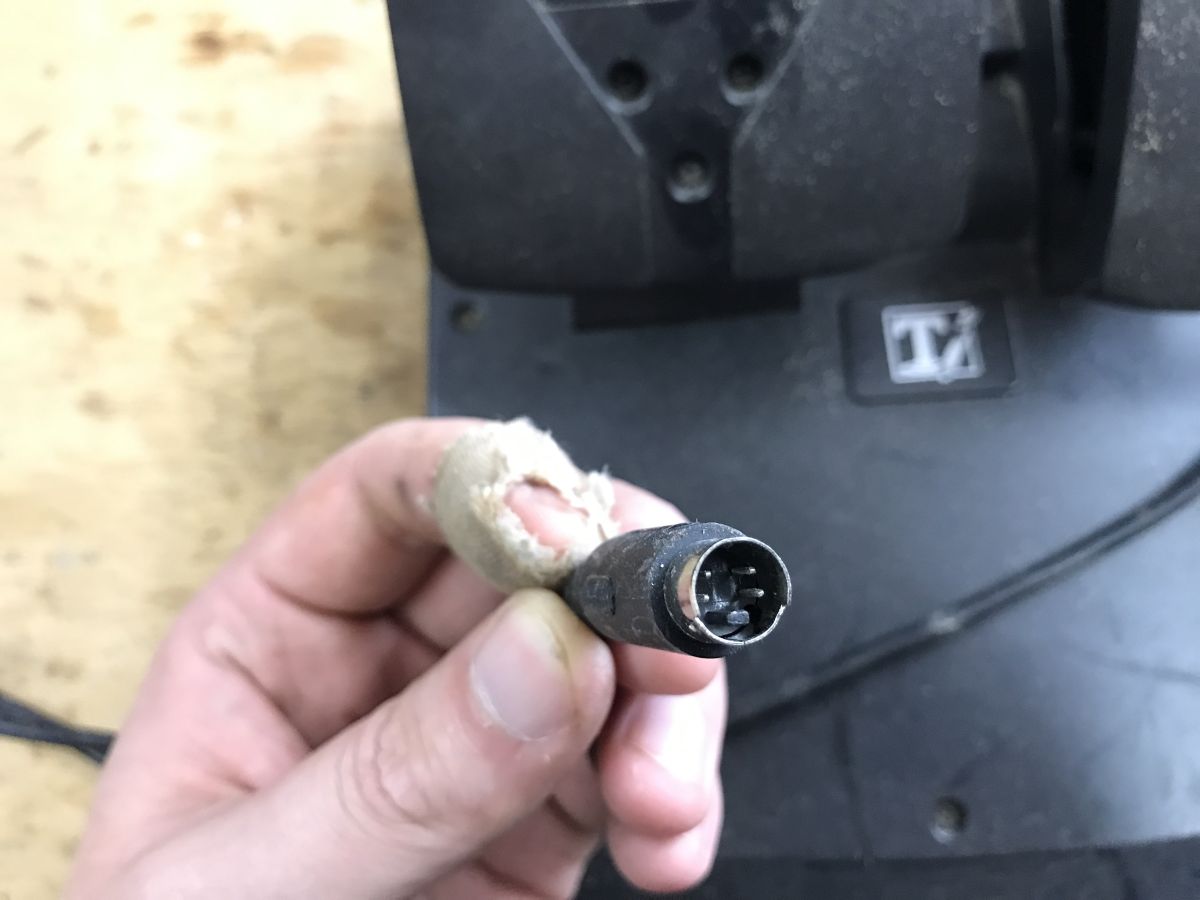
    Close-up of a mini-DIN plug held in a hand, with a black device housing in the background. How a racing set is built - steering wheel and pedals for USB/Playstation and PS/2 How a racing set is built - steering wheel and pedals for USB/Playstation and PS/2
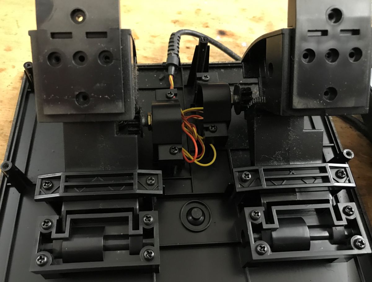
    We take a look, and it turns out that the whole mechanism is a spring + potentiometer.
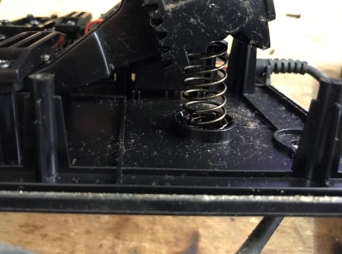
    How a racing set is built - steering wheel and pedals for USB/Playstation and PS/2 How a racing set is built - steering wheel and pedals for USB/Playstation and PS/2
    By the way, I don't see a controller here, so maybe this connector didn't go directly to the computer.... but that's a secondary issue.

    Summarising , it's all just based on buttons (zero-one state - pressed or released), potentiometers (as a voltage divider - reading from the ADC) and possibly digital outputs to turn on/off LEDs and motors. There is not much philosophy here.
    It should be possible to bring this to life with PIC , there are enough ADC channels, input pins reasonably too:
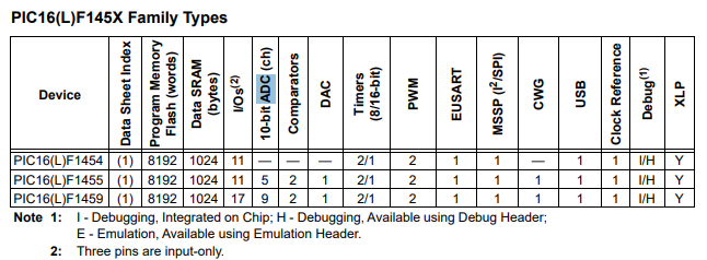
    How a racing set is built - steering wheel and pedals for USB/Playstation and PS/2
    There is nothing left to do but to rewire the acquired electronics under the PIC and prepare the USB descriptors. This I will already show in the next topic.
    Have you ever created your own joystick/gamepad project based on a microcontroller?

    Cool? Ranking DIY
    Helpful post? Buy me a coffee.

    About Author
    p.kaczmarek2
    Moderator Smart Home
    Offline 
    p.kaczmarek2 wrote 14459 posts with rating 12468, helped 650 times. Been with us since 2014 year.
  • ADVERTISEMENT
  • #2 21894109
    maestro16s
    Level 11  
    Posts: 21
    Help: 1
    Rate: 7
    The pedals were usually connected to the steering wheel. i don't see a socket in the steering wheel here, so maybe it's not a kit
  • ADVERTISEMENT
  • #3 21894120
    p.kaczmarek2
    Moderator Smart Home
    Posts: 14459
    Help: 650
    Rate: 12468
    I confirm, these are two pieces of hardware from different sources. I just kept them with the idea of using the PIC. If something moves, I'll show it in the DIY.
    Helpful post? Buy me a coffee.
  • #4 21904017
    noel200
    Level 27  
    Posts: 1892
    Help: 36
    Rate: 813
    There are already projects on the web for making your own controller based on an old steering wheel or something like that. I just made one on the same steering wheel, only I made my own pedals, because the ones from the kit got lost. I put an atmega 32u4 in there and the software is mmjoy2 https://github.com/MMjoy/mmjoy_en/wiki.
    The other one I found once but haven't tested personally is EMC Utility. It seems much more powerful. But the free version is light. You have to pay for the better one. But it seems to be somehow in the form of a donation via fb. I haven't checked the other project. Now I saw that some new beta was released in February. https://github.com/ebolzMagy/EMCFFBV2/releases https://github.com/ebolzMagy/EMCFFBV2/wiki
    MMJOY I even fired it up on a bluepile table with a 500ppr industrial incremental quadrature encoder connected for a test.
    Attachments:
    • MMjoy220161101.zip (17.48 MB) You must be logged in to download this attachment.
    • EMCUtilitylite.zip (2.89 MB) You must be logged in to download this attachment.
📢 Listen (AI):

FAQ

TL;DR: This teardown shows 2 simple sensing methods—"just potentiometers" and button inputs—inside an MX-V9 racing wheel and PS/2 pedals. It helps DIY builders restore or rewire old sets for USB HID use with a PIC16LF1659, including steering, pedals, LEDs, and vibration motors. [#21891725]

Why it matters: The thread reduces an old racing set to practical building blocks you can test, repair, or repurpose without guessing how the controls work.

Item Connection shown Main sensing method Extra hardware
MX-V9 Vibration wheel USB or PlayStation Steering potentiometer Vibration motors, LED, bottom mode switch
Pedal unit PS/2-style connector Spring + potentiometer No visible controller board inside

Key insight: Old racing wheels are usually simpler than they look: buttons give digital inputs, potentiometers provide analog position, and motors or LEDs use basic switched outputs. [#21891725]

Quick Facts

  • The steering wheel uses a 20 kΩ linear potentiometer marked B, and the post explicitly notes that B = linear while A = logarithmic. [#21891725]
  • The MX-V9 wheel supports 2 host paths in the teardown: USB and PlayStation, selected by a switch on the bottom and matched to separate cabling. [#21891725]
  • The vibration system uses motors with unbalanced weights, which convert motor rotation into shake feedback instead of measuring position. [#21891725]
  • The pedal assembly uses a spring + potentiometer mechanism, and the author found no visible controller board inside the pedal housing. [#21891725]
  • The proposed rebuild target is a PIC16LF1659, chosen because it has enough ADC channels and input pins for buttons and axes. [#21891725]

How is the MX-V9 Vibration steering wheel built inside for USB and PlayStation operation?

It is built around simple modules connected by plugs, with a steering potentiometer, buttons, an LED, vibration motors, and a board that routes signals to either USB or PlayStation. The post also shows a bottom PlayStation/PC switch and notes that the housing is held by many screws, which matches an older, modular design. [#21891725]

What components in a racing wheel and pedal set are used to detect steering angle and pedal position?

A potentiometer detects both steering angle and pedal position in this set. The wheel uses one linear 20 kΩ potentiometer for steering, while the PS/2 pedal unit uses a spring linked to a potentiometer to convert pedal travel into an analog position signal. [#21891725]

Why is a 20 kΩ linear potentiometer marked B used for a steering wheel instead of a logarithmic type A potentiometer?

A 20 kΩ type B potentiometer is used because steering needs a linear position response across the wheel’s travel. The post states that B means linear and A means logarithmic, and also says the logarithmic version would not make sense for this application. [#21891725]

What is the "black dot" chip on old game controller PCBs, and why is it so hard to identify?

It is the main unidentified controller chip on the board, and the post says its exact circuit cannot be determined. "Black dot" is an unidentified board chip that handles controller logic, but its exact circuit type is not visible in this wheel, which makes board-level identification difficult during repair or reverse engineering. [#21891725]

How do the vibration effects in the MX-V9 steering wheel work with motors and unbalanced weights?

The wheel creates vibration by spinning motors fitted with unbalanced weights. That offset mass generates shake as the motor rotates, so the controller only needs to switch the motors on and off instead of measuring another analog axis. [#21891725]

In the PS/2 pedal unit, how does the spring plus potentiometer mechanism measure throttle or brake travel?

The pedal pushes against a spring and turns a potentiometer as it moves. That means pedal travel changes the potentiometer position, so the connected controller can read the changing voltage and map it to throttle or brake level. [#21891725]

Why might a PS/2 pedal set have no visible controller board inside, and where is the signal processing usually done?

In this teardown, the pedal unit appears to be only a sensor mechanism, so the signal processing is likely done outside the pedal housing. The author explicitly says no controller is visible inside and suggests the PS/2-style connector may not have gone directly to the computer. [#21891725]

How would you rewire an old steering wheel and pedals to a PIC16LF1659 so it appears as a USB HID game controller?

You would move the buttons, potentiometers, LEDs, and vibration outputs onto the PIC16LF1659 and then expose them through USB HID. 1. Rewire each button to input pins. 2. Connect wheel and pedal potentiometers to ADC-capable pins. 3. Prepare the USB descriptors so the device reports buttons and axes as a game controller. [#21891725]

What is a USB HID descriptor, and how does it define buttons and axes for a custom joystick or racing wheel?

A USB HID descriptor is the data definition that tells the host what controls the device exposes. In this project context, it defines which inputs act as buttons, which analog readings act as axes, and how the rewired PIC-based controller should appear to a PC over USB. [#21891725]

PlayStation mode vs USB mode in a racing wheel — what changes in wiring, signaling, or compatibility?

In this wheel, the visible change is host connection and compatibility, not the basic sensor hardware. The post shows a PlayStation/PC switch on the bottom and a cable arrangement for PlayStation or USB, while the internal controls still remain buttons, potentiometers, LED outputs, and vibration motors. [#21891725]

Which PIC microcontroller features matter most when building a DIY gamepad or steering wheel, such as ADC channels and input pins?

ADC channels and enough digital input pins matter most in the build shown here. The author says a PIC can handle the project because the controls reduce to button inputs, potentiometers read through the ADC, and digital outputs for LEDs or motors. [#21891725]

What is ADC in a microcontroller, and how is it used to read potentiometers in pedals and steering wheels?

ADC is the microcontroller block that reads an analog voltage and turns it into a digital value. Here it would read the voltage-divider output from the steering and pedal potentiometers, so wheel angle and pedal travel can be reported as game-controller axes. [#21891725]

What problems should you check when restoring an old racing wheel with lots of screws, plug-in modules, and hot-glued parts?

Check mechanical fasteners, connector seating, potentiometer wear, glued LED mounting, and cable condition first. The teardown shows many screws, plug-in modules, a hot-glued LED, and old internal construction, so loose connectors, cracked plastic, or unstable sensor readings are realistic failure points during restoration. [#21891725]

Can Hall sensors or rotary encoders replace potentiometers in a DIY racing wheel, and what are the trade-offs?

This thread does not show Hall sensors or rotary encoders; it shows only potentiometer-based sensing. The practical takeaway is narrower: the original hardware already uses a 20 kΩ steering potentiometer and pedal potentiometers, so a DIY rebuild can work without changing the sensing method. [#21891725]

How have makers created their own joystick or gamepad projects based on a microcontroller for PC or console use?

They reuse the same pattern shown here: digital inputs for buttons, ADC reads for axes, and USB HID reporting to the host. The author also notes an earlier PIC16LF1659 project that already ran as an HID keyboard or mouse, then says a gamepad or joystick can be realized in a similar way. [#21891725]
Generated by the language model.
ADVERTISEMENT