logo elektroda
logo elektroda
X
logo elektroda

Backup & Restore of Xradiotech/Allwinner XR806/XR809 Flash in Windows: Guide & Demonstration

divadiow  32 3939 Cool? (+5)
📢 Listen (AI):

TL;DR

  • A Windows guide demonstrates reading and restoring internal flash from Xradiotech/Allwinner XR806 modules, including a WXU (T103C-HL) used in a Tuya TRV16 radiator valve.
  • UART download mode requires pulling PB02 to ground at power-on, then PhoenixMC reads and writes the flash through the Debug menu.
  • Set the flash length to 200000, and PhoenixMC saves the backup as flash_A_0x0_L_0x200000.bin in its root folder.
  • The same process restores the dump after renaming .bin to .img, and XR809 only adds grounding PB02 and PB03.
  • The backup may contain Wi‑Fi credentials, so it should be made before cloud pairing or after pairing with a test AP.
Generated by the language model.
Here I will demonstrate how the internal flash of the Xradiotech/Allwinner XR806 (and XR809 - see note at bottom) can be read to file in Windows. Although there is not yet an OpenXR806 cloud-free alternative firmware to use on devices that have the XR806 at heart, flash firmware backups are useful in development and research and for general backup purposes.

One Tuya module seen in the wild based on XR806 is the WXU (T103C-HL). Also available as WXU-IPEX - datasheets attached.

To date on Elektroda XR806 has been spotted in:
Avatto TRV16-WIFI radiator valve
Avatto SWT60 Smart Watering Timer
Allwinner development board

Also: QOTO QT-08W Solar Power Smart Water Valve

XR806 uses 5mm x 5mm QFN40 package and 4mm x 4mm QFN32 packages for different feature lists.

Pin layout diagram of the XR806 chip by Xradiotech Pin diagram for XR806 BM2I Diagram of XRADIO XR806 chip with pin labels.


Table showing GPIO multiplexing for XR806Bxxx.


To get into UART download mode PB02 needs to be pulled to ground at power-on.

on the WXU PB02 is the 3rd pad up from the bottom on the right-hand side of the module as you look at the top

Schematic of an integrated circuit with GPIO and UART connections.

or from the bottom:
Diagram of electronic circuit pins with labels.

and again from the top with WXU shown mounted on PCB from TRV16, which I will also use to demonstrate flash backup


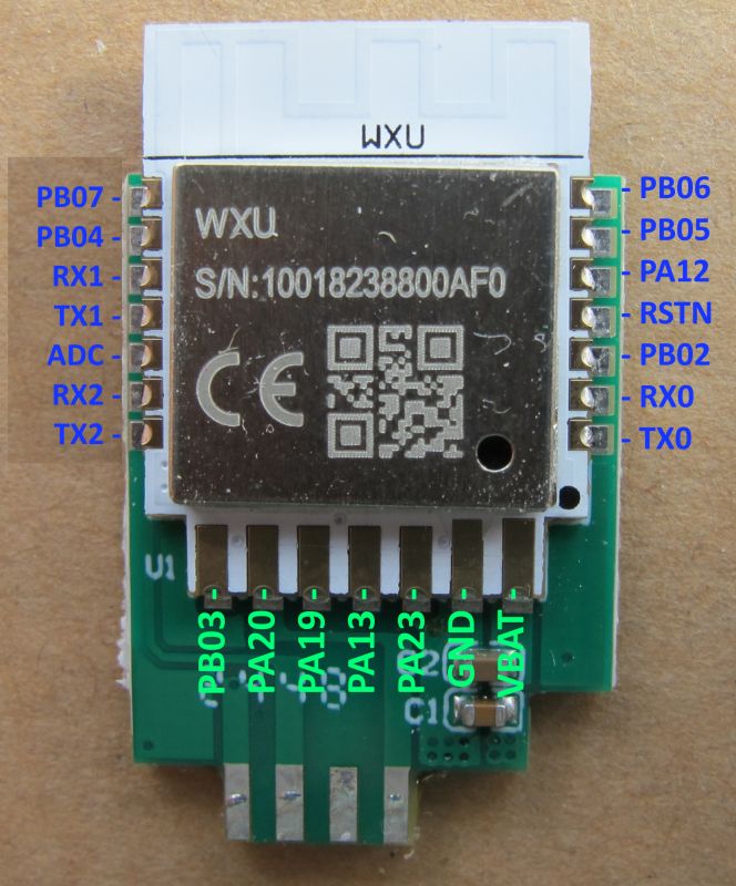
Soldering can be performed direct to WXU contacts or, in the case of this WXU on PCB from TRV16, I have chosen to solder to the breakout pads instead for all but PB02.

Electronic module with markings and QR code Printed circuit board with labels and connectors.

Electronic module with wires on a blue mat. Green PCB with attached colored wires against a keyboard background.

USB-TTL RX -> XR806 TX
USB-TTL TX -> XR806 RX
3.3V -> XR806 VBAT
USB-TTL GND -> PSU GND -> XR806 GND

Flash writing and reading is performed in the PhoenixMC program, available from https://github.com/openshwprojects/FlashTools/tree/main/XRadioTech-AllWinner

Main text areas are in Chinese, so here are some translations to aid navigation

PhoenixMC software interface for firmware updates.
Graphical user interface for a flash memory operation application. Screenshot of software settings window for firmware programming.

Connect XR806 as above and power on. Set appropriate baud on the main page (this may need to be lower if your wires are too long or you're using pogo pins), open the Debug menu. It should communicate with the XR806 and unlock the text fields. Change the length box text to 200000 and click Read.

Animated read image
Flash operation application window with various options and settings.

Flash backup will be saved to file called flash_A_0x0_L_0x200000.bin in the PhoenixMC root folder
Properties window of the binary file flash_A_0x0_L_0x200000.bin in Windows.

In this mode you can also read the flash ID. eg:
Dialog window with a warning from the phoenixMC program, showing BROM version and flash ID.

which looks to be Winbond W25Q16JV or W25Q16DV in my case.

To restore a backup simply rename your backup file extension from .bin to .img (or change the filtering in the open dialog box to *.*) and flash back with the blue Update button. eg:

Screenshot of PhoenixMC software showing binary file details.


This process is identical for the XR809 except for the need to ground both PB02 and PB03. Original XR809-specific guide: https://www.elektroda.com/rtvforum/topic3806769.html


Your backup may contain your wifi credentials so backup should be done prior to pairing device with cloud platforms or pair/unpair with test AP. Please share your backup files for analysis and archive in the collection https://github.com/openshwprojects/FlashDumps/tree/main/IoT

Alternatively, PM me the file and I'll happily flash/pair to test AP/unpair and take new backup.

About Author
divadiow
divadiow wrote 4800 posts with rating 845 , helped 417 times. Live in city Bristol. Been with us since 2023 year.

Comments

p.kaczmarek2 06 May 2025 00:27

With our recent research and development, it seems increasingly likely that it's also possible to flash XR chips without grounding extra pins, as long as the firmware is built with command line enabled... [Read more]

divadiow 06 May 2025 07:25

we need more real XR806 backups to test. The TRV XR806 one we have does not appear to support it but it is trying to do TuyaMCU comms on the flashing UART, so maybe theyre getting in the way. If you... [Read more]

jmkrzyszt 09 Nov 2025 00:06

Hi, Thank you @divadiow for your instructions, I was able to dump factory firmware of my XR806 based Salcar TRV801W thermostatic radiator head. BTW, I've already open a pull request with that firmware... [Read more]

insmod 09 Nov 2025 00:56

This shouldn't happen, and unfortunately i don't know the reason. And i can't test it myself, since i don't have any XR806 module. For now, try https://github.com/openshwprojects/OpenBK7231T_App/r... [Read more]

jmkrzyszt 09 Nov 2025 02:14

Boot log from 1.18.128 looks almost the same as 1.18.207, there is only one difference, last number in one line before the last, which is now 0x2200d0. Added after 34 [minutes]: For those who may... [Read more]

divadiow 09 Nov 2025 13:43

Hmm. It's been a while since I flashed an XR806, I'll try when home later. I have an XR806 dev board and also, obviously, the WXU from probably the same TRV. I never did put the WXU back into the TRV to... [Read more]

jmkrzyszt 09 Nov 2025 14:02

before proceeding @divadiow could you please try with the factory firmware that I added to the FlashDumps repo? Maybe results from booting it on your module can shed more light on the issue with my... [Read more]

divadiow 09 Nov 2025 14:25

Yep, I added that note. I was just about to post that I killed a board with the other dump there. It must be coded for that DC mode that eats the Allwinner boards. I could maybe try on 3.3v WXU instead... [Read more]

jmkrzyszt 09 Nov 2025 15:26

So for me it looks like my device's factory firmware, despite being built with SDK v1.2.1, is using DCDC, and that can be dangerous to other devices. [Read more]

divadiow 09 Nov 2025 16:01

interesting. This is the device I have from which WXU came from. It shows LDO used in this boot log of factory app post #7 https://www.elektroda.com/rtvforum/topic4118139.html Added after 15 [minutes]:... [Read more]

jmkrzyszt 09 Nov 2025 16:54

There is no separate WiFi module in my device, everything except an external LED dispaly is located on one and the same PCB, can be seen on the picture I posted. So my device may be very different from... [Read more]

divadiow 09 Nov 2025 17:06

yes indeed. do you know what your XR806 is fed with voltage-wise if powered normally as if unopened? [Read more]

jmkrzyszt 09 Nov 2025 19:43

I'm able to power up the device from batteries even when disassembled, however, I would be afraid of touching XR806 chip pins with a probe. Those are so tiny, so close one to another, so I can't be sure... [Read more]

divadiow 15 Nov 2025 00:10

You could build a DCDC version of OpenXR806 to see if that works. I don't know if that's a good idea or not. [Read more]

jmkrzyszt 15 Nov 2025 15:37

I guess you mean you don't know if that's safe for the device, don't you? [Read more]

divadiow 15 Nov 2025 15:46

Pretty much yes. But if yours is DCDC now it sounds like it'd be ok. Depends on whether you want to take any risks I guess. Or wait until someone who knows more chimes in [Read more]

jmkrzyszt 12 Dec 2025 23:18

Hi, I've decided to try with a custom DCDC build. Following the guide, I've submitted a pull request and the image has been built. Can you please have a look at https://github.com/openshwprojects/OpenBK7231T_App/pull/1893... [Read more]

divadiow 13 Dec 2025 07:14

I think that's all I'd do, toggle LDO off/DCDC on, see what works. Added after 2 [minutes]: but I don't want to be leading you down a path if it means killing the chip. I just know what I'd fiddle... [Read more]

jmkrzyszt 13 Dec 2025 10:38

Assuming my attempt to configure a custom DCDC image was successful, I can see no difference when trying to boot it on my device, compared to the default OpenXR806 image. Boot log looks exactly the same... [Read more]

FAQ

TL;DR: Read 0x200000 bytes from an XR806 in PhoenixMC after grounding PB02 at power-on; as one tester put it, "flashing works as expected" once wiring and mode entry are correct. This FAQ helps Windows users back up, restore, and troubleshoot XR806/XR809 flash, boot, and power-mode issues on Tuya-based boards. [#21507996]

Why it matters: A verified flash backup can recover a device after failed OpenXR806 tests and helps research board-specific boot, power, and bootloader differences.

Item XR806 XR809
UART download entry pins Ground PB02 at power-on Ground PB02 + PB03 at power-on
Typical read length shown 0x200000 Same process stated
Restore method Rename .bin to .img, then Update Same process stated
Main risk discussed Boot/power mismatch, flash ID or boot issues Same class of risk

Key insight: The flash procedure itself is straightforward; the hard part is board-specific compatibility. Power mode, crystal setting, UART choice, and bootloader assumptions can decide whether OpenXR806 boots or fails with jedec: 0x0 and no xip section.

Quick Facts

  • PhoenixMC readback uses a length of 200000 hex, producing flash_A_0x0_L_0x200000.bin in the program root folder. [#21507996]
  • XR806 packages mentioned are 5 mm × 5 mm QFN40 and 4 mm × 4 mm QFN32, depending on feature set. [#21507996]
  • One failed-stability case improved only after raising supply to 4.3 V, because the module browned out when starting its AP. [#21746241]
  • A factory boot log from one TRV801W showed XR806 SDK v1.2.1, HF clock 40,000,000 Hz, and CPU clock 160,000,000 Hz. [#21745789]
  • On a disassembled TRV801W, measured voltages included about 4.1 V on VBAT, 3.3 V on several rails, and about 1.5 V on a pad marked 1V8. [#21746389]

How do I back up the internal flash of an Xradiotech/Allwinner XR806 in Windows using PhoenixMC?

Use PhoenixMC in UART download mode and read out 0x200000 bytes. 1. Wire USB-TTL RX/TX, 3.3 V, and GND, then pull PB02 to GND during power-on. 2. In PhoenixMC, choose a working baud rate and open the Debug menu until the text fields unlock. 3. Set the length box to 200000 and click Read. PhoenixMC saves the dump as flash_A_0x0_L_0x200000.bin in its root folder. [#21507996]

What steps are needed to restore an XR806 flash backup in PhoenixMC after reading it out as a .bin file?

Rename the backup from .bin to .img and flash it with PhoenixMC's blue Update button. If you do not rename it, you can instead change the file filter in the open dialog to *.*. One user restored original device behavior by re-flashing the factory dump after OpenXR failed to boot, which confirms the write path works when the image matches the board. [#21507996]

XR806 vs XR809 flashing procedure — what extra pins need to be grounded to enter UART download mode on each chip?

XR806 needs PB02 grounded at power-on, while XR809 needs both PB02 and PB03 grounded. The thread states the rest of the PhoenixMC read and write process is identical between the two chips. That makes pin strapping the main procedural difference when entering the boot ROM download path. [#21507996]

What is UART download mode on the XR806, and how does pulling PB02 to ground at power-on enable it?

UART download mode is the XR806 boot mode that accepts flash read and write commands over a serial link. Pulling PB02 low during power-on forces that mode, which lets PhoenixMC communicate with the chip, unlock its fields, read flash ID, and dump or restore the internal flash. In the thread, this mode was the required entry point for Windows backup and recovery. [#21507996]

Where is PB02 located on the Tuya WXU module, and what wiring is needed to connect an XR806 to a USB-TTL adapter for flashing?

On the WXU, PB02 is the third pad up from the bottom on the right side when viewing the module from the top. Wire USB-TTL RX to XR806 TX, USB-TTL TX to XR806 RX, 3.3 V to VBAT, and common ground from USB-TTL and PSU to XR806 GND. The author soldered to breakout pads for most signals and directly to PB02 for mode entry. [#21507996]

Why does OpenXR806 sometimes boot with errors like "jedec: 0x0", "fdcm_open() failed", and "no xip section" on XR806 devices?

These errors point to a boot-time mismatch in flash access or low-level board configuration. One failing device logged jedec: 0x0, then fdcm_open() failed, read img cfg failed, and no xip section, while a blank XR806 board booted OpenXR806 1.18.207 normally. The thread linked such failures to board-specific variables like power mode, crystal selection, and bootloader assumptions rather than to PhoenixMC flashing itself. [#21745789]

How can I troubleshoot an XR806 device like the Salcar TRV801W when OpenXR806 flashes successfully but its AP never appears?

First confirm the factory dump restores the device, then compare UART logs, power mode, and crystal assumptions. In the TRV801W case, the factory image restored normal behavior, but OpenXR still showed no AP and only error logs. Check whether the board uses DCDC or LDO, whether the bootloader matches the board's HOSC setting, and whether logs appear on UART2 instead of UART0. Keeping a verified backup is the safest baseline before each change. [#21745789]

Which UART on XR806 hardware carries boot logs or Tuya MCU communication — UART0, UART1, or UART2?

UART assignment is board-specific, but this thread showed boot logs on UART2 and suspected Tuya MCU traffic on UART0 in one TRV801W. The tester saw no UART0 boot output, while UART2 printed full startup logs, including SDK and Wi-Fi details. They also suspected UART0 might serve Tuya MCU communication because the line appeared reserved yet mostly idle during observation. [#21745789]

What is TuyaMCU Debug Assistant, and how was it used in attempts to trigger flashing on XR806 without grounding extra pins?

TuyaMCU Debug Assistant is a serial utility used here to fake Tuya MCU interaction so the app can finish booting before another flash attempt. The tester launched it with a fake PID, let the app boot, closed the COM port, and then retried PhoenixMC without grounding pins. That method still did not push the TRV XR806 into download mode, although an AWOL development-board dump did respond to the command-based approach. [#21540572]

How should I choose the baud rate in PhoenixMC for XR806 flashing, especially when using long wires or pogo pins?

Start with a conservative baud rate and lower it if the link is unstable. The guide explicitly warns that long wires or pogo pins may require a lower baud, because PhoenixMC must first communicate successfully and unlock its text fields before reading. If the Debug page does not respond reliably, reduce speed before changing anything else. [#21507996]

What do the boot log lines "INT DCDC" and "INT LDO / EXT PWR" mean on XR806, and how can they hint at power configuration issues?

They indicate which internal power path the firmware expects at boot. "INT DCDC" is a power-setting status line that reports the chip is configured around its internal DC-DC regulator, while "INT LDO / EXT PWR" reports an LDO or external-power path. In the thread, a factory image showed INT DCDC : enable, while OpenXR builds that booted elsewhere still showed INT LDO / EXT PWR: enable. That mismatch became a key clue in failed boots and board-risk discussions. [#21746224]

Why can flashing factory XR806 dumps from another device be risky, and how can DCDC-vs-LDO firmware differences potentially damage a board?

Cross-flashing is risky because a dump may embed board-specific power assumptions. One tester reported they had already killed a board after flashing another device's backup and linked the failure to a power mode that “eats the Allwinner boards.” Later discussion tied the risk to DCDC-versus-LDO differences seen in boot logs, so a foreign factory dump can do more than fail to boot; it can overstress incompatible hardware. [#21746179]

What is XTAL or HOSC frequency on XR806 boards, and how can a 24/26/32/40 MHz bootloader mismatch affect booting?

XTAL or HOSC is the board's main crystal frequency, and the bootloader must match it. "XTAL is the hardware crystal clock source that sets the XR806's high-frequency timing, and bootloaders are built for fixed values such as 24, 26, 32, or 40 MHz." The thread notes the default precompiled bootloader targets 40 MHz, while variants also exist for 24, 26, and 32 MHz. A mismatch can prevent normal boot even when flashing succeeds. [#21779853]

How do I change OpenXR806 power settings to build a custom DCDC image, including the CONFIG_PWR_INTERNAL_DCDC and VDD_SENSE options?

Use the SDK configuration, not only a superficial patch, to switch the power path. One tester ran make menuconfig in the SDK root, changed the VDD_SENSE mode, and saved a .config showing CONFIG_PWR_INTERNAL_DCDC=y, with internal LDO and external power disabled. That produced a build whose boot log still needed verification, because another test suggested the image might still expose LDO behavior at runtime. [#21779851]

What is the supported way to modify sdk/OpenXR806/.config in an OpenBK7231T_App pull-request build so custom settings like DCDC mode or CONFIG_BOOTLOADER are actually applied?

The thread does not confirm a supported pull-request method that reliably applies those .config changes. A tester patched sdk/OpenXR806/.config from pre_build.sh, but the resulting builds behaved as if key settings were ignored or only partly honored. Enabling CONFIG_BOOTLOADER=y also triggered build errors for missing symbols and structure fields, which suggests the PR pipeline and full SDK config flow were not aligned in that experiment. [#21779892]
Generated by the language model.
%}