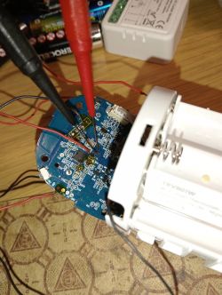
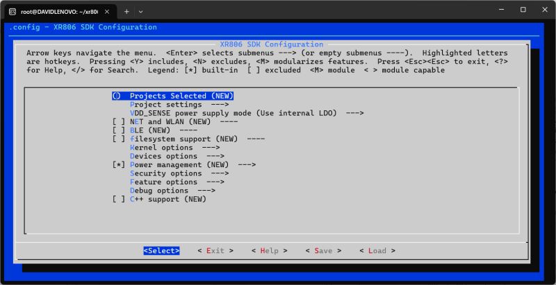
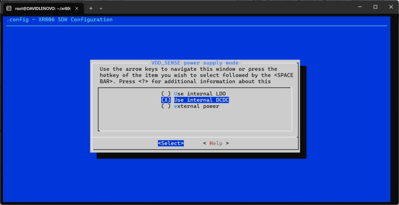
Here I will demonstrate how the internal flash of the Xradiotech/Allwinner XR806 (and XR809 - see note at bottom) can be read to file in Windows. Although there is not yet an OpenXR806 cloud-free alternative firmware to use on devices that have the XR806 at heart, flash firmware backups are useful in development and research and for general backup purposes.
One Tuya module seen in the wild based on XR806 is the WXU (T103C-HL). Also available as WXU-IPEX - datasheets attached.
To date on Elektroda XR806 has been spotted in:
Avatto TRV16-WIFI radiator valve
Avatto SWT60 Smart Watering Timer
Allwinner development board
Also: QOTO QT-08W Solar Power Smart Water Valve
XR806 uses 5mm x 5mm QFN40 package and 4mm x 4mm QFN32 packages for different feature lists.
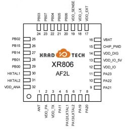
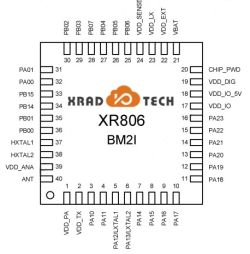
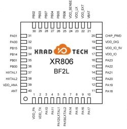
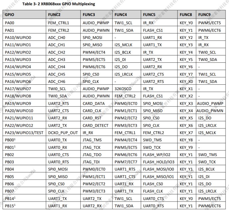
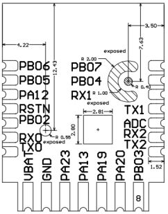
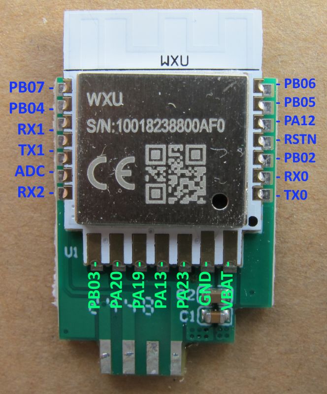
To get into UART download mode PB02 needs to be pulled to ground at power-on.
on the WXU PB02 is the 3rd pad up from the bottom on the right-hand side of the module as you look at the top
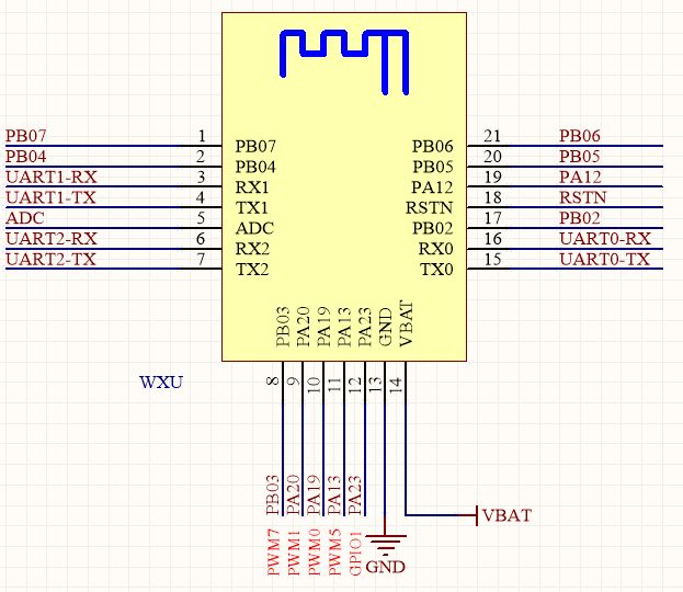
or from the bottom:
and again from the top with WXU shown mounted on PCB from TRV16, which I will also use to demonstrate flash backup
Soldering can be performed direct to WXU contacts or, in the case of this WXU on PCB from TRV16, I have chosen to solder to the breakout pads instead for all but PB02.
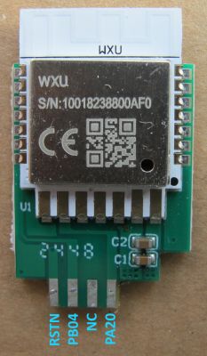
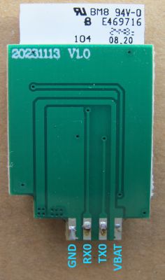
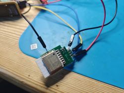
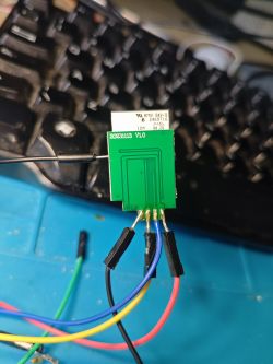
USB-TTL RX -> XR806 TX
USB-TTL TX -> XR806 RX
3.3V -> XR806 VBAT
USB-TTL GND -> PSU GND -> XR806 GND
Flash writing and reading is performed in the PhoenixMC program, available from https://github.com/openshwprojects/FlashTools/tree/main/XRadioTech-AllWinner
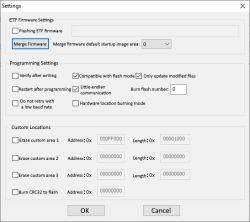
Main text areas are in Chinese, so here are some translations to aid navigation
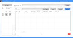
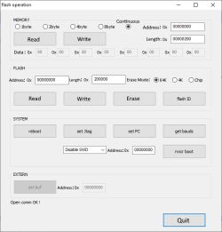
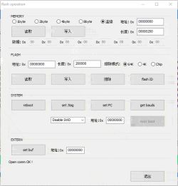
Connect XR806 as above and power on. Set appropriate baud on the main page (this may need to be lower if your wires are too long or you're using pogo pins), open the Debug menu. It should communicate with the XR806 and unlock the text fields. Change the length box text to 200000 and click Read.
Animated read image
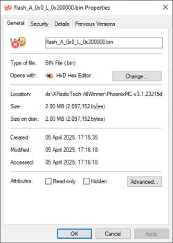
Flash backup will be saved to file called flash_A_0x0_L_0x200000.bin in the PhoenixMC root folder
In this mode you can also read the flash ID. eg:
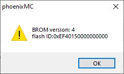
which looks to be Winbond W25Q16JV or W25Q16DV in my case.
To restore a backup simply rename your backup file extension from .bin to .img (or change the filtering in the open dialog box to *.*) and flash back with the blue Update button. eg:
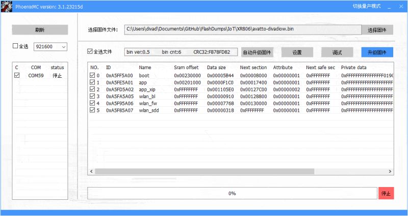
This process is identical for the XR809 except for the need to ground both PB02 and PB03. Original XR809-specific guide: https://www.elektroda.com/rtvforum/topic3806769.html
Your backup may contain your wifi credentials so backup should be done prior to pairing device with cloud platforms or pair/unpair with test AP. Please share your backup files for analysis and archive in the collection https://github.com/openshwprojects/FlashDumps/tree/main/IoT
Alternatively, PM me the file and I'll happily flash/pair to test AP/unpair and take new backup.
One Tuya module seen in the wild based on XR806 is the WXU (T103C-HL). Also available as WXU-IPEX - datasheets attached.
To date on Elektroda XR806 has been spotted in:
Avatto TRV16-WIFI radiator valve
Avatto SWT60 Smart Watering Timer
Allwinner development board
Also: QOTO QT-08W Solar Power Smart Water Valve
XR806 uses 5mm x 5mm QFN40 package and 4mm x 4mm QFN32 packages for different feature lists.


To get into UART download mode PB02 needs to be pulled to ground at power-on.
on the WXU PB02 is the 3rd pad up from the bottom on the right-hand side of the module as you look at the top

or from the bottom:

and again from the top with WXU shown mounted on PCB from TRV16, which I will also use to demonstrate flash backup

Soldering can be performed direct to WXU contacts or, in the case of this WXU on PCB from TRV16, I have chosen to solder to the breakout pads instead for all but PB02.


USB-TTL RX -> XR806 TX
USB-TTL TX -> XR806 RX
3.3V -> XR806 VBAT
USB-TTL GND -> PSU GND -> XR806 GND
Flash writing and reading is performed in the PhoenixMC program, available from https://github.com/openshwprojects/FlashTools/tree/main/XRadioTech-AllWinner
Main text areas are in Chinese, so here are some translations to aid navigation


Connect XR806 as above and power on. Set appropriate baud on the main page (this may need to be lower if your wires are too long or you're using pogo pins), open the Debug menu. It should communicate with the XR806 and unlock the text fields. Change the length box text to 200000 and click Read.
Animated read image

Flash backup will be saved to file called flash_A_0x0_L_0x200000.bin in the PhoenixMC root folder

In this mode you can also read the flash ID. eg:

which looks to be Winbond W25Q16JV or W25Q16DV in my case.
To restore a backup simply rename your backup file extension from .bin to .img (or change the filtering in the open dialog box to *.*) and flash back with the blue Update button. eg:

This process is identical for the XR809 except for the need to ground both PB02 and PB03. Original XR809-specific guide: https://www.elektroda.com/rtvforum/topic3806769.html
Your backup may contain your wifi credentials so backup should be done prior to pairing device with cloud platforms or pair/unpair with test AP. Please share your backup files for analysis and archive in the collection https://github.com/openshwprojects/FlashDumps/tree/main/IoT
Alternatively, PM me the file and I'll happily flash/pair to test AP/unpair and take new backup.
Cool? Ranking DIY


