
.
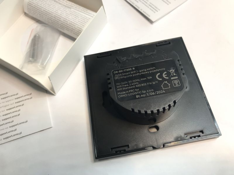
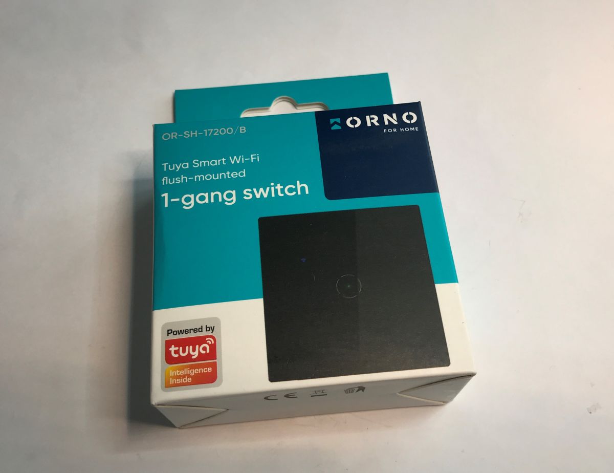
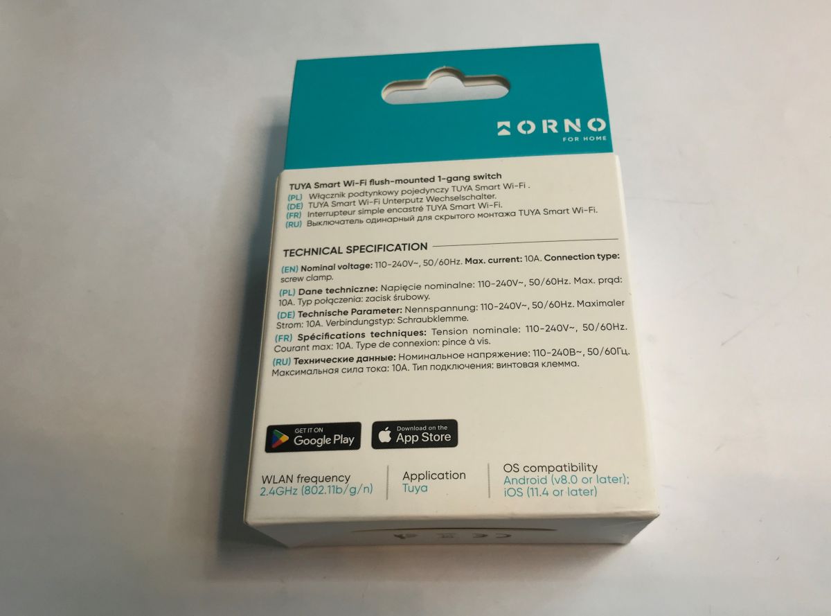
The Orno OR-SH-17200 WiFi Tuya single switch is another product that can be easily freed from the cloud and connected to the Home Assistant. What's more, inside it you will find a CBU module based on the BK7231N, which allows various interesting modifications after changing its firmware. Unlike the CB3S and WB3S, it can even easily handle WS2812 LEDs! Here I will show just the inside of such a switch and demonstrate how to change its firmware.


.
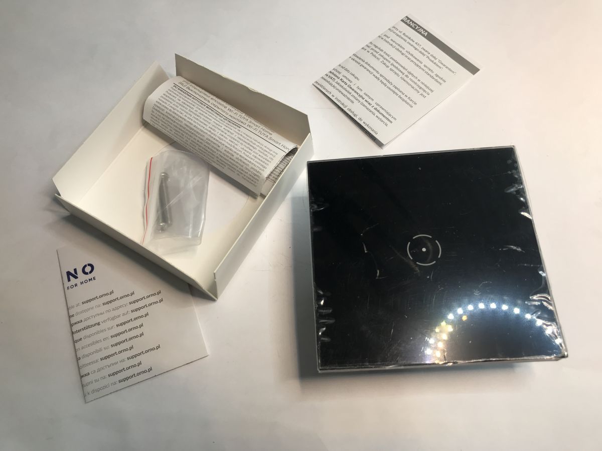
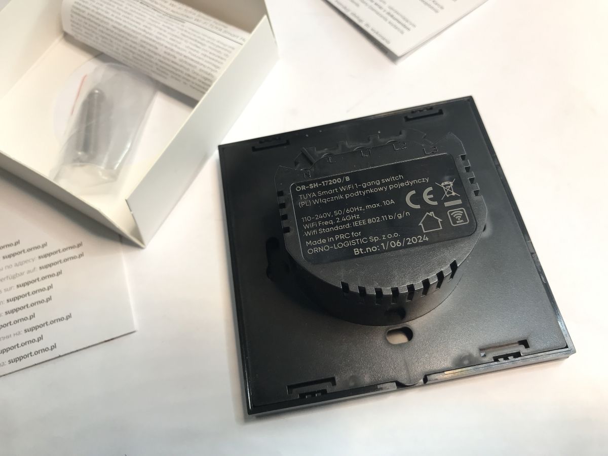
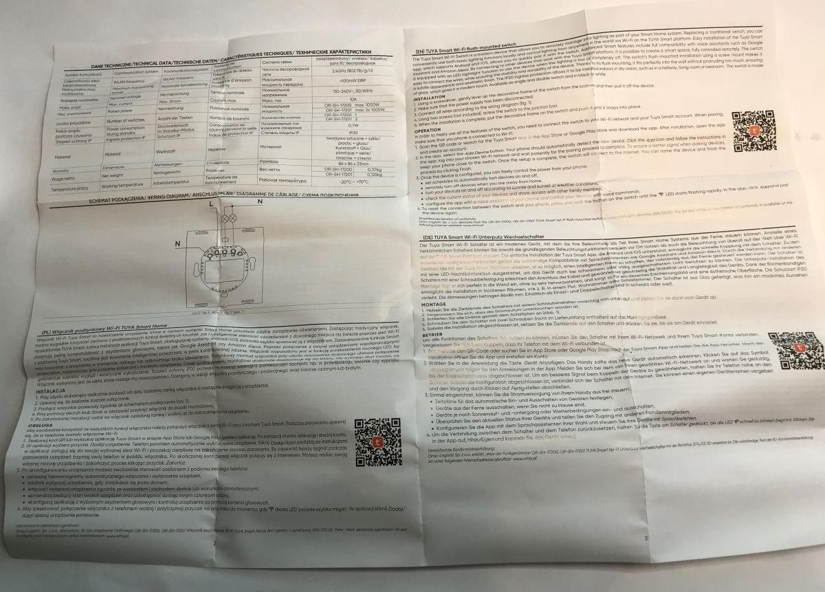
The unit shown comes in various configurations and colours - we have a white and black option. You can also get it in double and triple versions. The kit comes with a switch (its dimensions are 86x86x35mm), two mounting screws for the box and instructions:

.
The unit requires a neutral wire for operation.
.
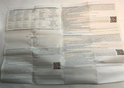
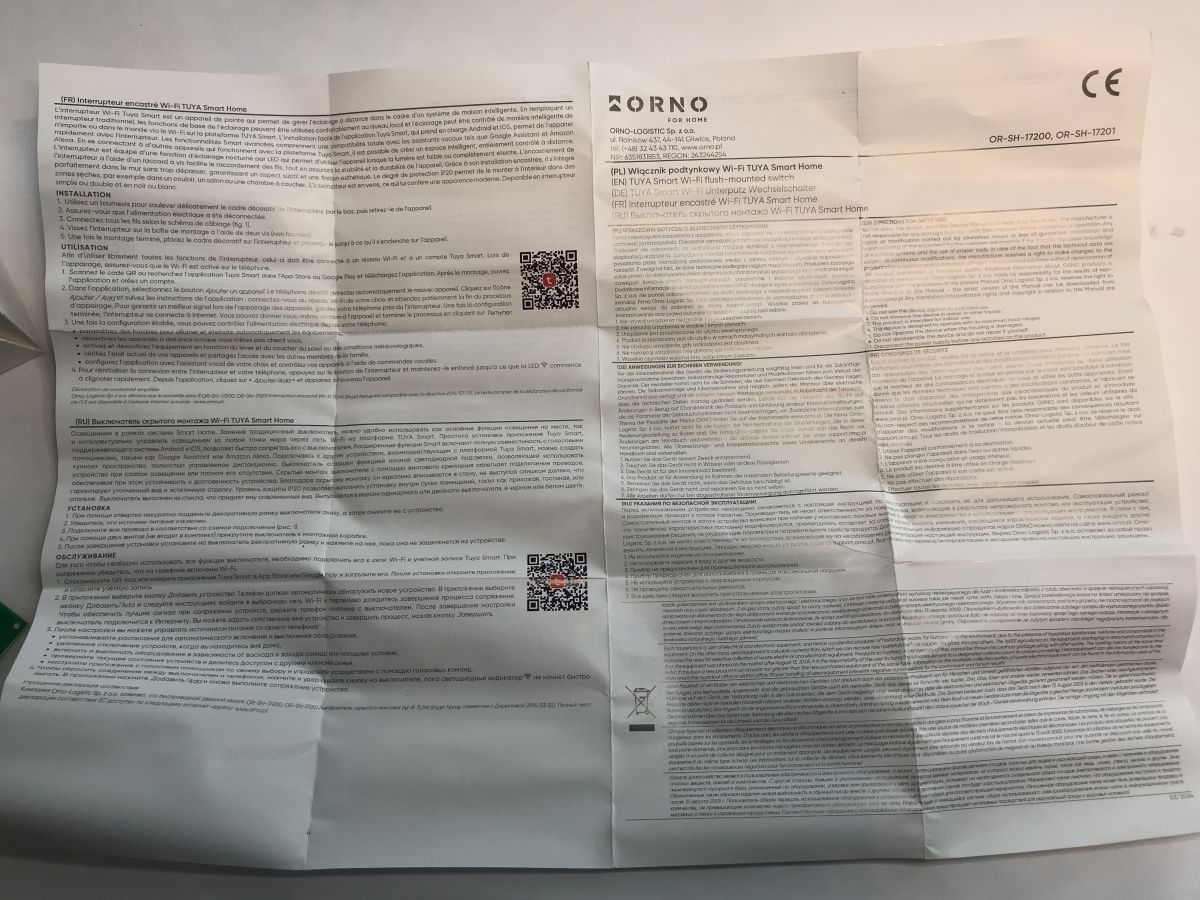
Here are pictures of the installation instructions and pairing with Tuya. The pairing with Tuya is of no use to me as I am changing the software of this equipment to my own.


.
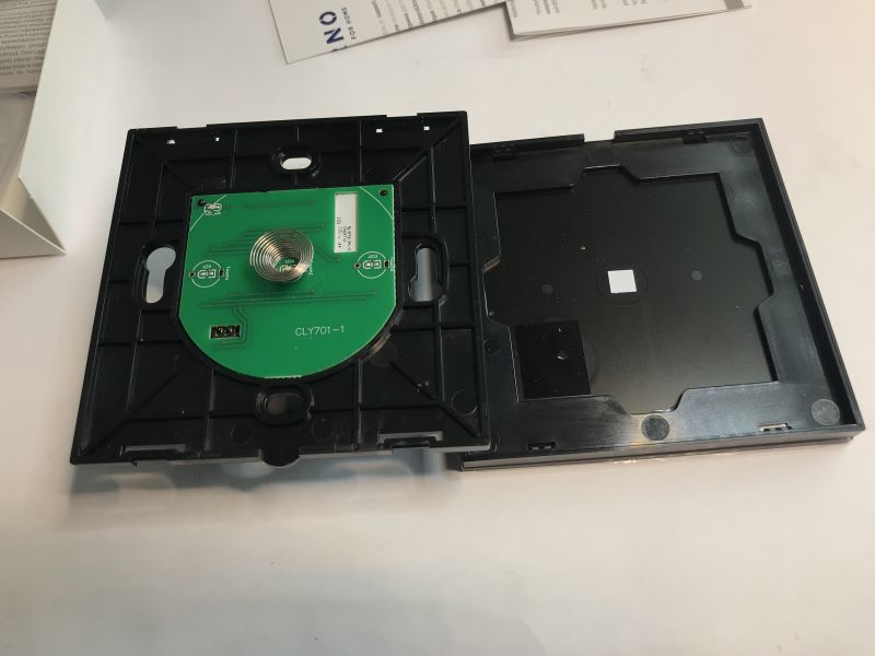
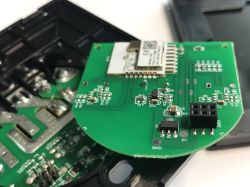
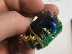
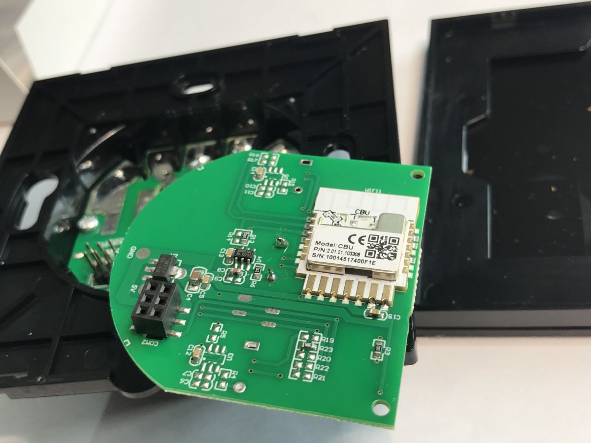
Let's now move on to the presentation of the interior. We undermine the front panel.
.
PCB designation: CLY701-1
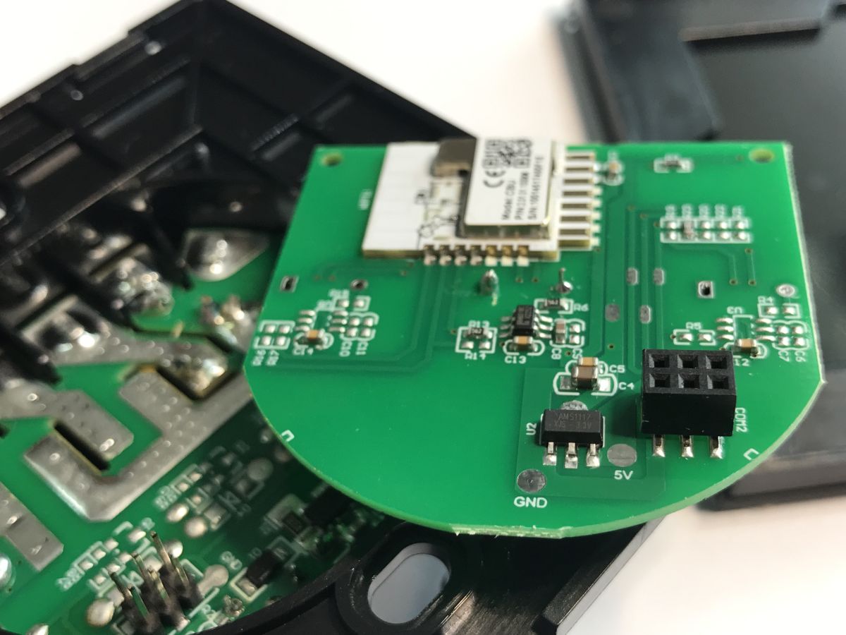
We remove the board with the WiFi module:
.
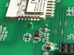
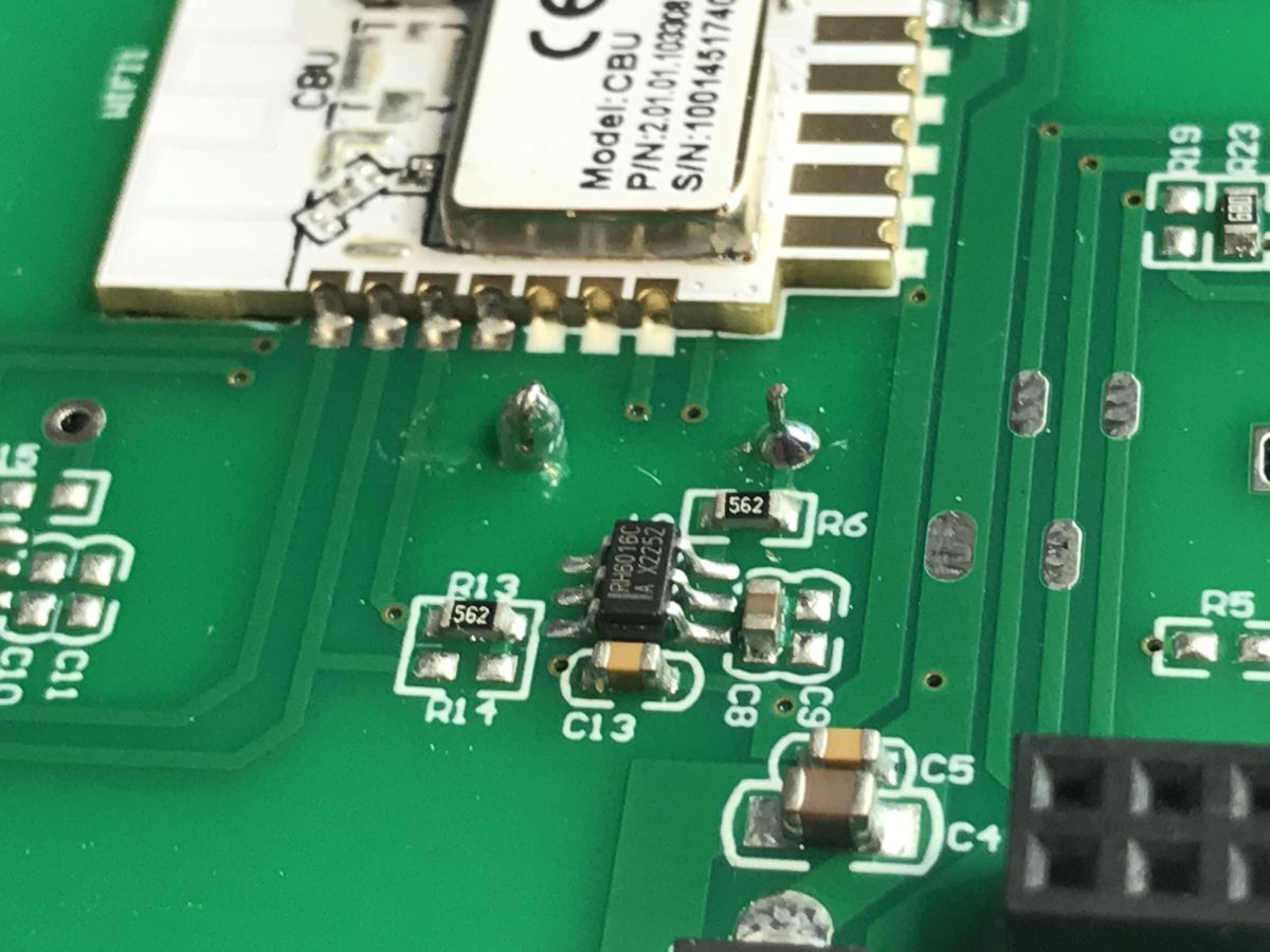
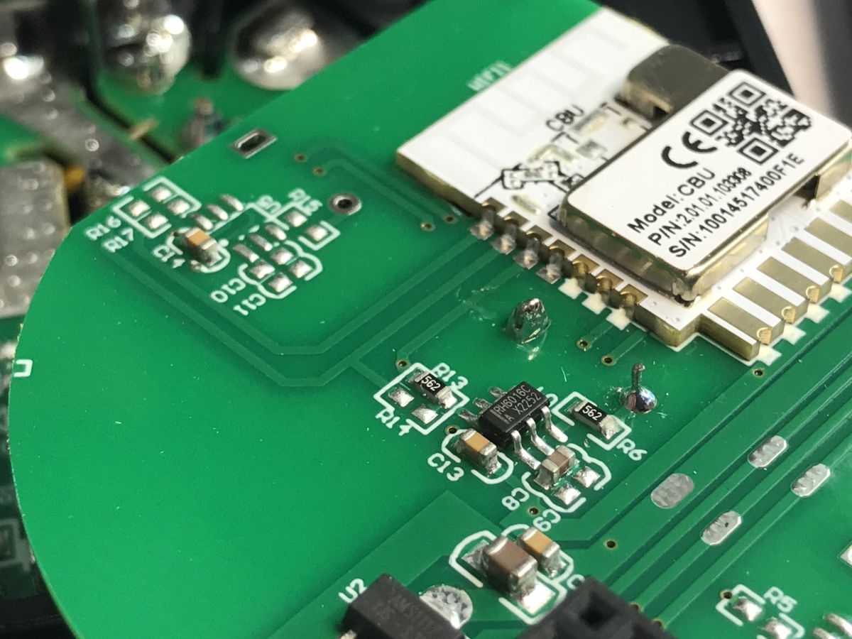
Inside you can see the WiFi CBU module, the LDO 3.3V AMS1117-3.3 regulator and the touch button controller (only one is soldered on - there are empty spaces for two more).
.
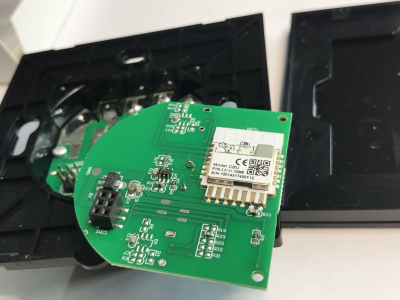
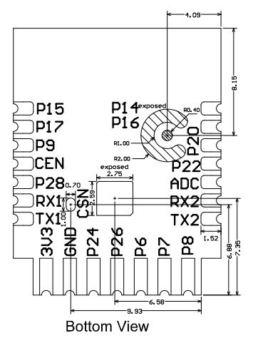
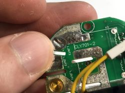
CBU outputs (bottom view):
.
| Pin number | | Symbol | I/O type | Function | |
| 1 | | P14 | I/O | | Common GPIO, which can be reused as SPI_SCK (Correspond to Pin 11 of the IC) |
| | . 2 | P16 | | I/O | Common GPIO, which can be reused as SPI_MOSI (Correspond to Pin 12 of the IC) |
| 3 | P20 | | I/O | Common GPIO (Correspond to Pin 20 of the IC) |
| 4 | P22 | I/O | | Common GPIO (Correspond to Pin 18 of the IC) |
| 5 | | ADC | I/O | | ADC, which corresponds to P23 on the internal IC (Correspond to Pin 17 of the IC) |
| 6 | RX2 | | I/O | UART_RX2, which corresponds to P1 on the internal IC. | TX2 | I/O | UART_TX2, which is used for outputting logs and corresponds to P0 of the internal IC (Correspond to Pin 29 of the IC) |
| | 8 | P8 | I/O | Support hardware PWM (Correspond to Pin 24 of the IC) |
| | 9 | P7 | | I/O | Support hardware PWM (Correspond to Pin 23 of the IC) |
| | 10 | P6 | I/O | Support hardware PWM (Correspond to Pin 22 of the IC) |
| | 11 | P26 | | I/O | Support hardware PWM (Correspond to Pin 15 of the IC) |
| | 12 | P24 | | I/O | Support hardware PWM (Correspond to Pin 16 of the IC) |
| | 13 | GND | P | Power supply reference ground |
| 14 | 3V3 | P | Power supply 3V3 |
| 15 | TX1 | I/O | UART_TX1, which is used for transmitting user data and corresponds to Pin 27 of the IC. For the MCU solution, please refer to CBx Module. |
| 16 | . RX1 | I/O | UART_RX1, which is used for receiving user data and corresponds to Pin 26 of the IC. For the MCU solution, please refer to CBx Module. |
| 17 | . P28 | I/O | Common GPIO (Correspond to Pin 10 of the IC) |
| 18 | CEN | I/O | Reset pin, low active (internally pulled high), compatible with other modules (Correspond to Pin 21 of the IC) |
| 19 | P9 | | I/O | Common GPIO (Correspond to Pin 25 of the IC) |
| | 20 | P17 | I/O | Common GPIO, which can be reused as SPI_MISO (Correspond to Pin 14 of the IC) |
| 21 | P15 | I/O | Common GPIO, which can be reused as SPI_CS (Correspond to Pin 13 of the IC) |
| Test point point | CSN | I/O | Mode selection pin. If it is connected to the ground before being powered on, enter the firmware test mode. If it is not connected or connected to VCC before being powered on, enter the firmware application mode. Correspond to Pin 19 on the internal IC. |
.
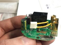
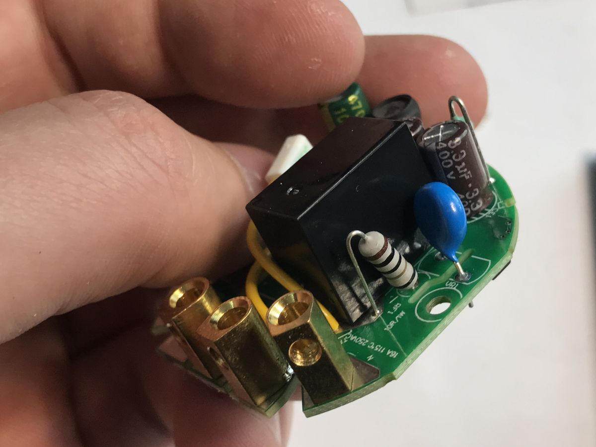
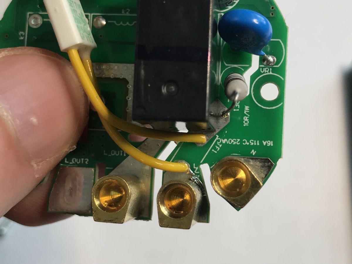
The second board is essentially the power supply (a small non-isolated step-down inverter) and relays (one here) along with the transistors and surge protection diodes that control them.

.
.
Interesting that there is a varistor inside - this fuse surprised me too. Why does it have such long legs?
Now it's time to change the firmware. You will need a USB to UART converter and a good 3.3V power supply, unless you solder 5V to the AMS1117-3.3V input from the board. It will come out the same. The programming tool is here:
https://github.com/openshwprojects/BK7231GUIFlashTool
Follow the readme there. There are 5V and GND pads on the board, so just whittle them down and you can solder the wires.

.
Soldered:

.
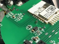
Then we solder the wires to the CBU pads - RX1 and TX1. This is what the whole thing looks like:

.
First we read the 2MB batch. My flasher immediately reveals the GPIO configuration:
.
Verbal description:
- Relay (channel 1) on P28
- WiFi LED on P22
- Button (channel 1) on P20
.
OBK template:
Instructions for importing the template:
Pairing with HA:
Other resources:
https://www.youtube.com/@electrodacom
Project homepage:
https://github.com/openshwprojects/OpenBK7231T_App
List of supported devices:
https://openbekeniot.github.io/webapp/devicesList.html
Finally, a few words about
an additional modification that is made possible by having a CBU module inside rather than, for example, a CB3S or CB2S. The CBU is distinguished by its access to P16, the hardware SPI, which is not normally derived:
How to access the hardware SPI port on the CB2S? We solder P16 (MOSI) to the QFN .
This allows control of WS2812 and similar diodes - only on this pin is this possible.
Animations OpenBeken WS2812B - new HTTP panel integration, PixelAnim driver .
The driver documentation is available in the linked topic. Appropriate commands are available, allowing such LEDs to be controlled from scripts and HA too. This means that after adding a single WS2812 to this switch, it can be used as a kind of status indicator controlled by e.g.. with Home Assistant.
In summary , this was another switch allowing a simple change of firmware to a
open source solution . This allows for the development of its functionality and independence from the manufacturer's servers and their potential tracking and surveillance. What's more, this particular series of devices allows for more modifications than usual, as it also offers access to P16, the pin needed to control individually addressable, coloured LEDs such as the WS2812. This allows us to create all sorts of custom controls showing states controlled from scripts or HA.
At this point I can recommend buying this product - there were no problems with reprogramming. I have programmed a set of switches from this series for a reader and the variants for two or three bulbs have a similar design - the flasher also detects GPIO configurations.


Comments