logo elektroda
logo elektroda
X
logo elektroda
Dostępna jest polska wersja

Czy wolisz polską wersję strony elektroda?

Nie, dziękuję Przekieruj mnie tam

The inside of the Polish retro power supply Polwat PWS-100 RM 24V/4A - has it survived the years of

p.kaczmarek2  27 2409 Cool? (+18)
📢 Listen (AI):

TL;DR

  • A teardown of the Polish PWS-100RM rail-mounted industrial power supply, recovered from scrap and rated for 24 V/4 A.
  • Inside, it uses a UC3844 flyback design with a full EMI filter, NTC inrush limiter, CNY75GA optocouplers, TL431 feedback, and a service-friendly chassis connection.
  • The label suggests a 2001 unit, and the load test pushed it to 5.44 A, with four 1 Ω resistors dropping output to about 21.75 V.
  • ESR checks found all electrolytic capacitors acceptable, and thermal imaging showed the Schottky diode and NTC heating most, while the switching transistor stayed cooler.
  • Despite heavy dirt and moisture traces, the supply still appears fully operational, though a longer test with proper heatsinks and lower current would be useful.
Generated by the language model.

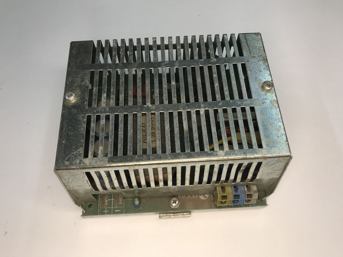
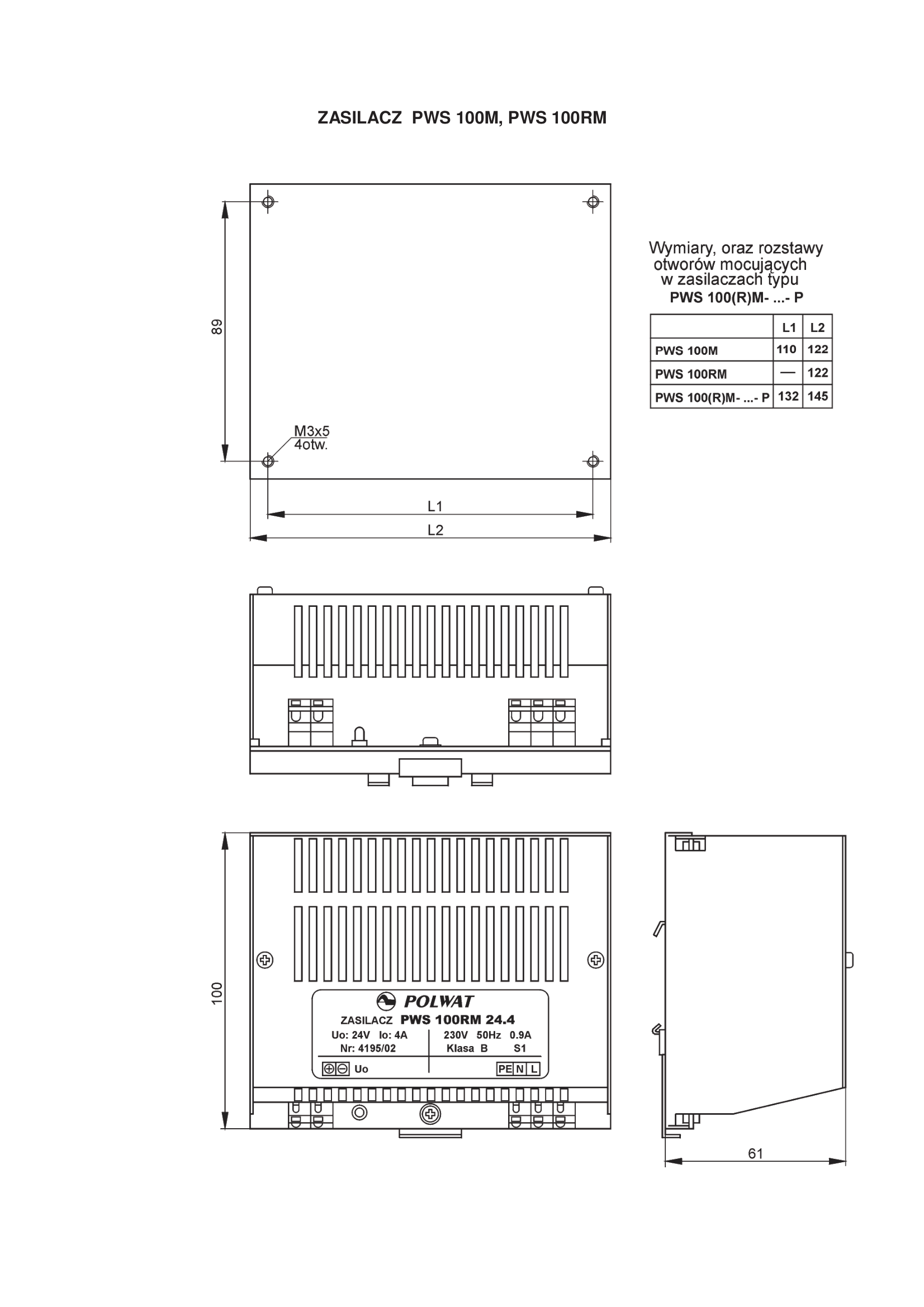
Today we take a look inside an old power supply made by a Polish company from Gliwice. I recovered the whole thing from scrap metal, so I'm going to check how this power supply has coped with years of use in an industrial device, examine whether it's still in working order at all, and finally show what heats up the most in it. The power supply shown here is the PWS-100RM model and is mounted on a TS-35 rail. It comes in different versions differing in output voltage, these include 5, 12, 24 and 48 V, although the documentation shows that the manufacturer is also happy to make a version with a different voltage.

The whole thing is designed to work as a stand-alone module. The label on my copy seems to suggest that this is piece number 4153 from 2001, so potentially this equipment is a good 25 years old! That could be right, as the manufacturer's company, as far as I can see, started in 1991.

Externally the whole thing is quite modest, one of the terminals (terminals) is broken off in my copy. Apart from that, there is only an LED indicating the presence of power. The hardware is fully passively cooled, which in an industrial environment, however, can be a plus, as it eliminates the problem of fans seizing and clogging up over time.

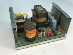
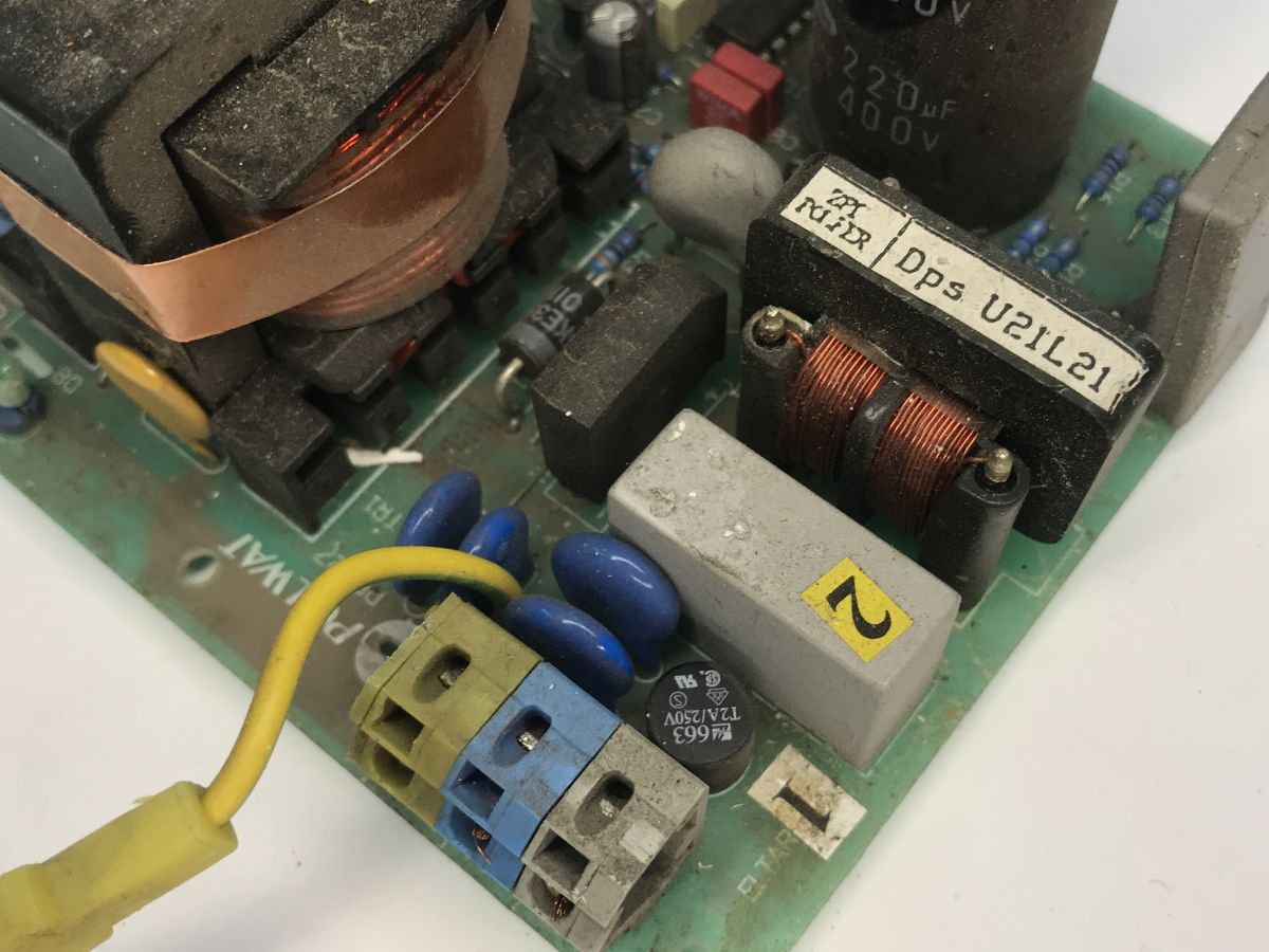
We remove the casing. You can immediately see that this is no budget Chinese power supply. No one has spared the copper here, the EMI filters seem to be fully present. You can also see significant dirt and traces of moisture.

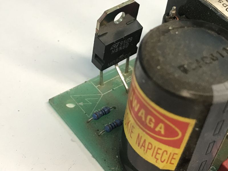
It's been a long time since I've seen a Polish "caution" sign on a 400 V mains voltage filtering capacitor.

The board is single-sided, simple but fulfilling. The thicknesses of the current paths and the appropriate insulation spacing instantly inspire confidence. There is a manufacturer's logo on the description layer.

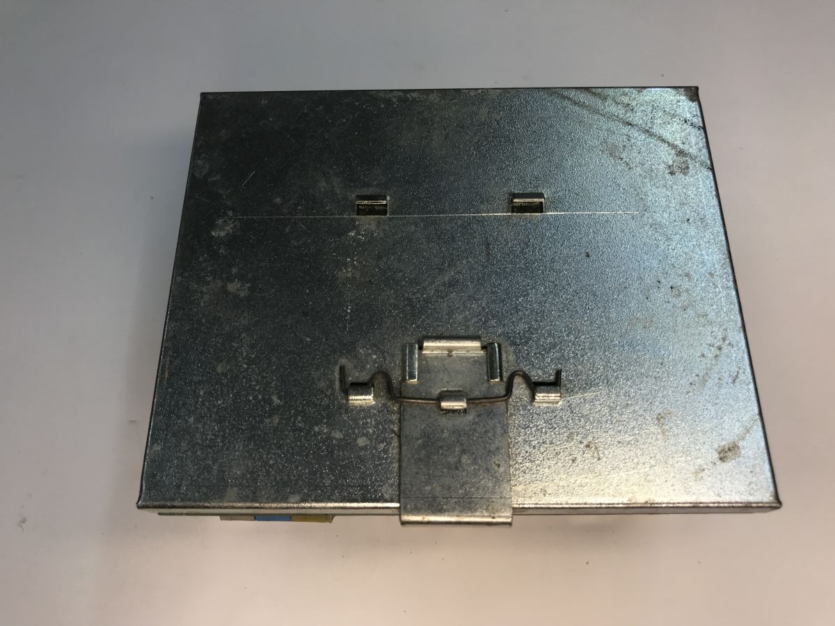
I like the fact that the PE is connected to the chassis by a connector rather than soldered. It looks like the whole thing has been thought out for servicing. In cheaper power supplies they would just solder it on.

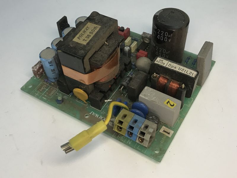
There is, of course, adequate protection on the input - a T2A/250V fuse and varistors to protect against surges from the mains:

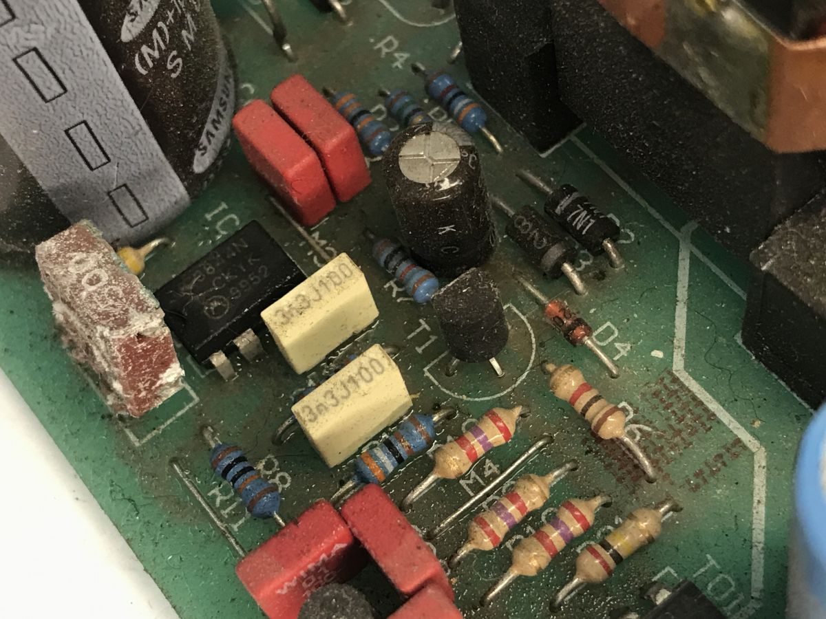
The power supply is based on the immortal UC3844 chip and is realised in flyback topology.

On the primary side, the RT, or thermistor resistor (NTC) limiting the inrush current, is conspicuous; it is soldered after the rectifier bridge, before the primary winding.
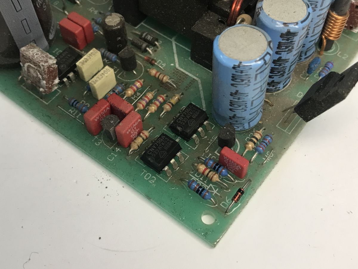
Feedback is provided by CNY75GA optocouplers, and I also see a TL431 (reference voltage) circuit there:

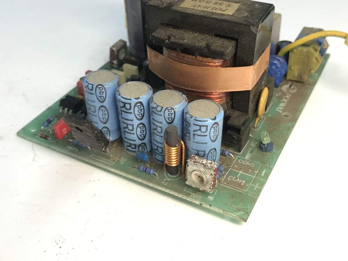
On the secondary side we have a small choke, a Schottky diode in a TO-220 housing and as many as four electrolytic capacitors. A potentiometer is used to adjust the output voltage over a small range.

It remains to determine the keying transistor - it appears to be an ST Microelectronics H8N80 N-MOSFET (800 V, 8 A).


Out of curiosity, I checked the most fail-safe component of such power supplies - the capacitors. They are not swollen, but perhaps they have lost their performance? I used my ESR70 for this.

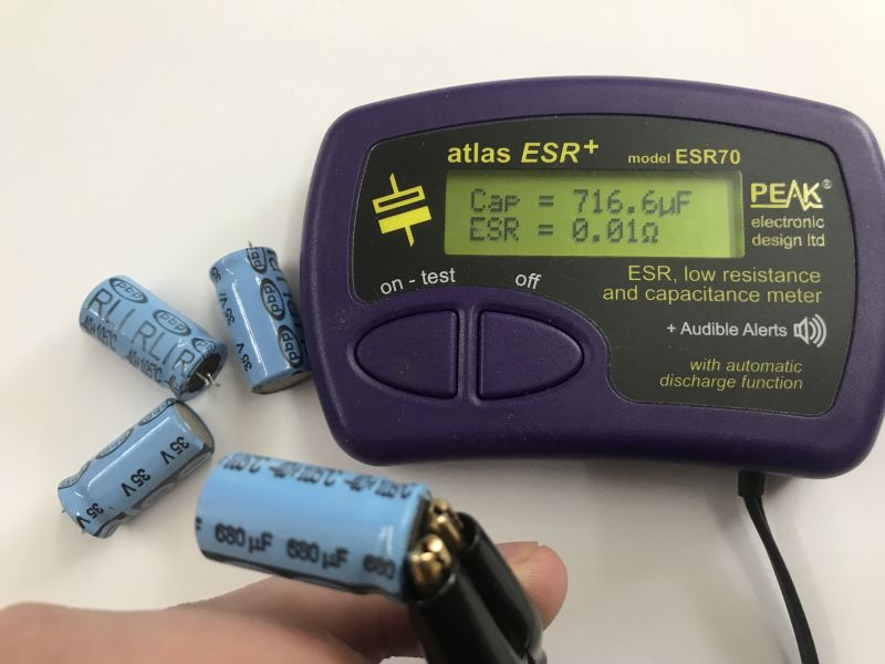
All the capacitors are fine, they can be soldered in place. By the way - that fix, the fine decoupling capacitor, is not from me, it was like that from the factory.


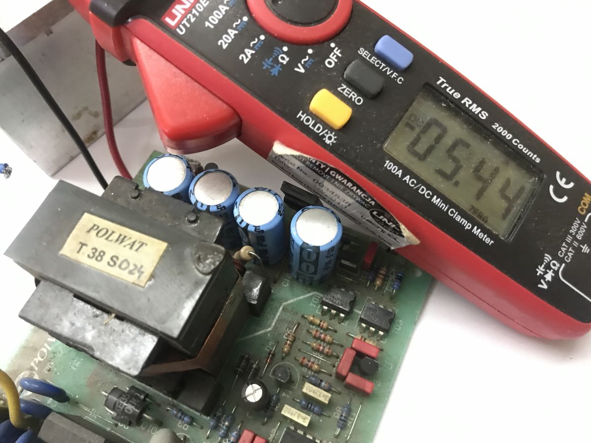
Time then for a more serious test. The power supply is scrap, I didn't expect it to be in working order, and I wasn't prepared to test it, so I loaded it with an exorbitant 5.44 A and saw what would happen. The no-load voltage is 24 V, with four 1 Ω power resistors each connected it drops to about 21.75 V.

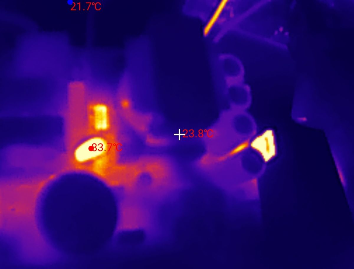
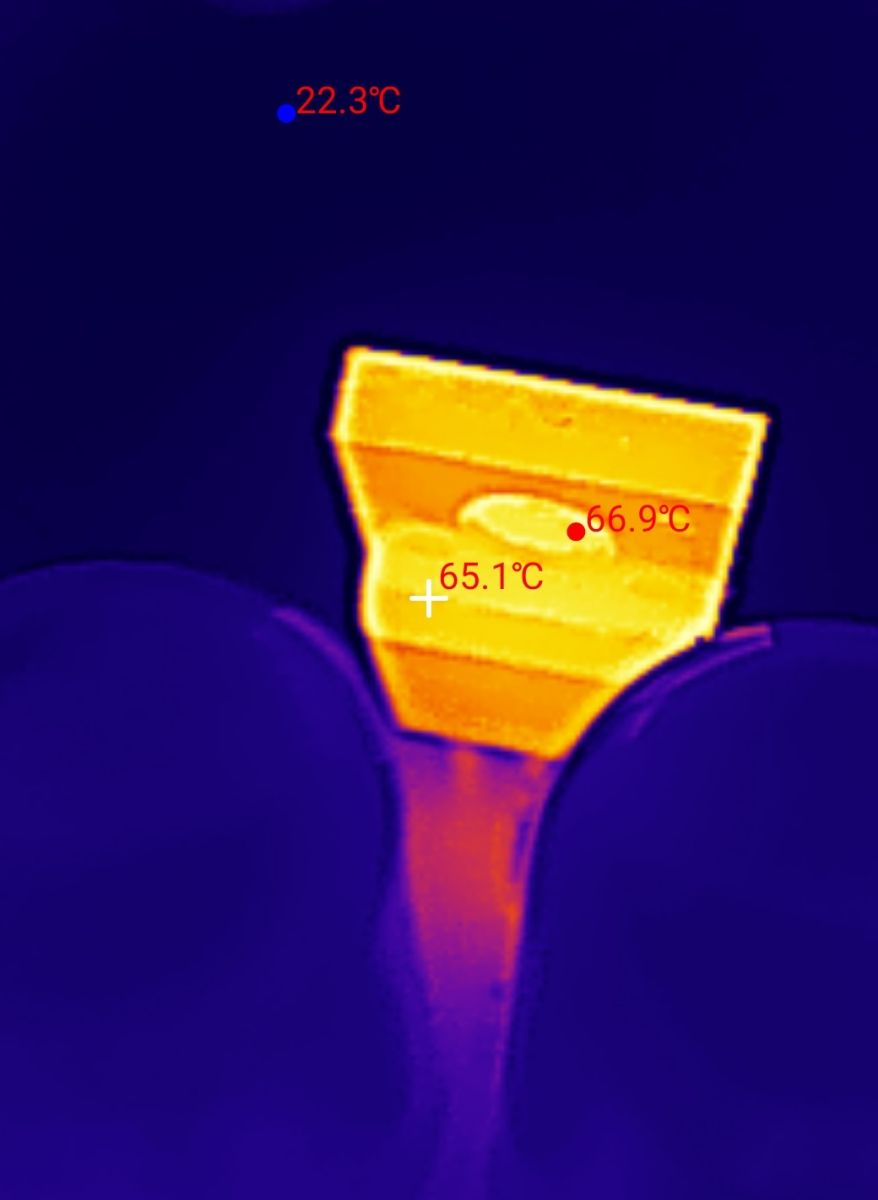
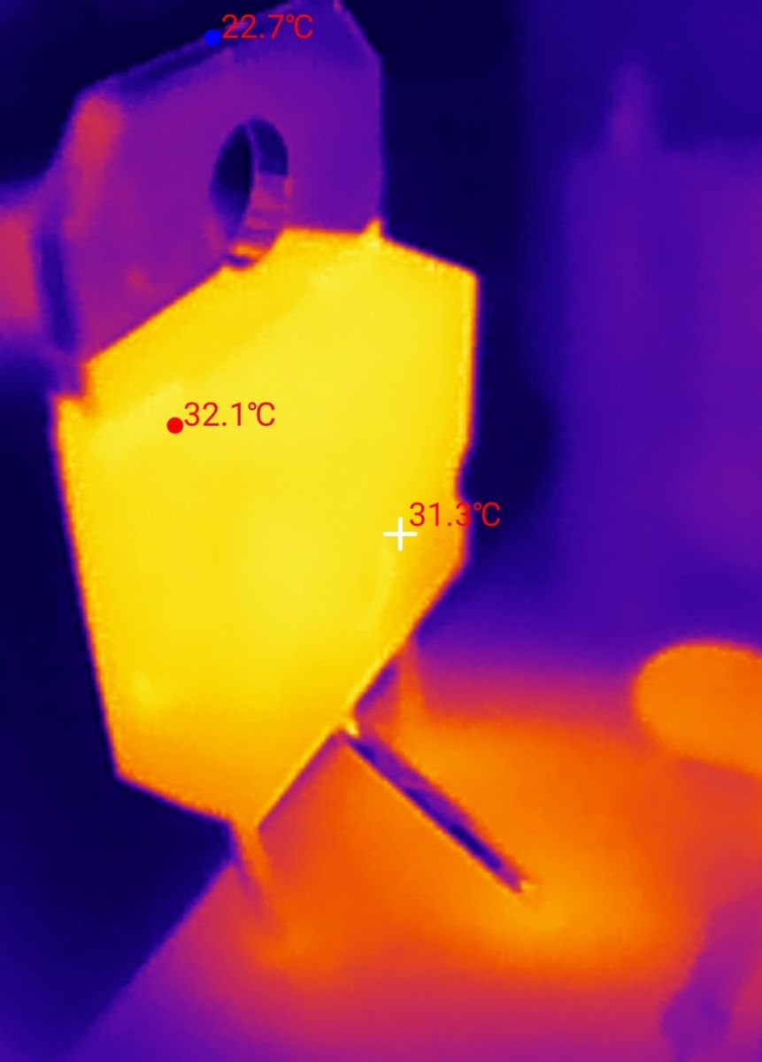
The most heated ... schottky diode and the thermistor (NTC) resistor. The keying transistor itself heats up slightly less.


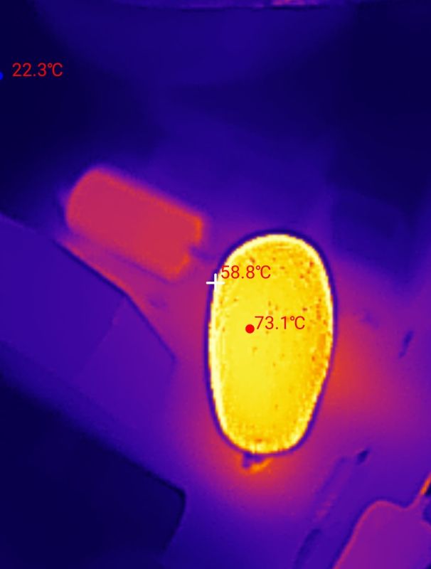
The thermal imaging camera images above clearly show the temperature distribution after load. The main transistor heats up significantly less:


Finally, it is still worth taking a look at the power supply parameters from the original manufacturer's documentation:

It is well apparent that this is no ordinary no-name power supply from China. The manufacturer specifies its parameters in detail, including ripple levels, radio interference and the electrical insulation strength of the mains-to-housing, mains-to-output and output-to-housing.

In summary, it appears that the power supply, despite its poor visual condition, is fully operational. A longer test would be useful, already with the appropriate heatsinks in place and at a lower current, but I do not currently have such a load at hand.

The design seems very solid and well thought-out, confirming the good reputation of older, industrial devices of Polish manufacture. If, after years of service, and probably some time spent on the scrap heap, the equipment is still working and holding its parameters, this testifies to the selection of good quality components and an adequate safety margin in the design.

My plans are to clean the board thoroughly, apply thermal conductive paste and perhaps use this power supply in one of my projects.

And have you guys had the opportunity to use this type of power supply in your factories or home workshops? How do you rate their failure rate?

About Author
p.kaczmarek2
p.kaczmarek2 wrote 14633 posts with rating 12647 , helped 655 times. Been with us since 2014 year.

Comments

Simon79 09 May 2026 14:41

Well designed equipment when refreshed can last another 25 years, unlike today's inverters made in china, not to mention EMC. [Read more]

p.kaczmarek2 09 May 2026 14:53

After removing the chassis, I checked the solders to see if I could see traces suggesting a previous component replacement. This time, however, it was not possible to draw a firm conclusion as many of... [Read more]

ArturAVS 09 May 2026 16:25

Capacitors in surprisingly good shape. MeanWell from https://www.elektroda.pl/rtvforum/viewtopic.php?p=19586151#19586151 refused to work after ~5 ciu years. Symptoms indicate dried out electrolytes. [Read more]

TechEkspert 09 May 2026 16:26

Impressive, heavyweight equipment :) I once came across a switch mode power supply from a Polish TV receiver Jowisz 04 it was an even bigger monster. I found a photo on elektroda.pl https://www.elektroda.pl/rtvforum/topic1454462.html The... [Read more]

Olkus 09 May 2026 19:48

Decent power supply, now something in this class of build quality costs a bit. Simple forward 1T, easily repaired and as you can see has stood the test of time very well :) I would also wash and keep,... [Read more]

krzbor 09 May 2026 21:59

You've got me worried. I also "bet" on these power supplies hoping they would live a long time. If you fix it then describe it on the electrode - I wonder what screwed up. [Read more]

rafcio363 09 May 2026 22:36

I had a similar 12V 10A beautiful design until it was nice to look in there. [Read more]

kris8888 10 May 2026 20:39

I've already repaired two of these, post #27 from the same Arthur topic: https://www.elektroda.pl/rtvforum/topic3827629.html And as for the title power supply, you can see that we can make solid stuff... [Read more]

TechEkspert 10 May 2026 21:07

Yes this Jupiter power supply was a nuisance, it had two high power resistors, in the form of a ceramic plate, which were damaging themselves by making a break. I guess the synchronicity was supposed... [Read more]

Janusz_kk 10 May 2026 21:31

But from where, it was all about interference, if the power inverter was running loose it would have to be very carefully disconnected and tightly sealed in a metal cage otherwise it would seep, stripes... [Read more]

TechEkspert 10 May 2026 22:35

Interesting, I hadn't seen that. All in all, this power supply was enclosed in a metal hollow cage made of thin sheet metal. [Read more]

coberr 10 May 2026 23:45

Great power supply. When I look at these idiotic EU regulations and the artificial and also idiotic generation of whole masses of electro-waste - it drives me nuts.... ABSOLUTELY EVERYTHING there contradicts... [Read more]

p.kaczmarek2 11 May 2026 00:15

As I started reading your message, I thought you were going to write about the capacitor at the flyback converter controller, the one that is usually fed from the additional winding (and via resistors... [Read more]

żarówka rtęciowa 11 May 2026 08:46

Hello Similar power supplies were produced by other Polish companies, here a 24V found in a scrap yard in 2014. I do not currently own it. It was intended for powering collective antenna systems. Pulse... [Read more]

pan_buka 11 May 2026 13:51

Cool stuff, I love the teardown of professional electronics, especially the slightly older ones. I just wonder how much this power supply cost in 2000 - I suspect it wasn't cheap. No wonder it doesn't... [Read more]

Olkus 11 May 2026 14:13

Right. I was confused by the UC3844, rather more common with forward topologies and this transistor at 800V, these are also often found in forwards. I didn't look at that the output choke is indeed tiny.... As... [Read more]

mkpl 11 May 2026 15:23

@ p.kaczmarek2 measure the capacitance of the class X capacitors. I've been struggling with them a lot lately, because with the current amount of "inverters" generating harmonics to the grid these capacitors... [Read more]

TechEkspert 11 May 2026 19:32

I used to use MW power supplies when a repetitive unit was hitting more locations. I checked on http://www.polwat.com.pl/ and PWS-40 and PWS 40RM look interesting. Does Polwat have a sales network... [Read more]

mkpl 11 May 2026 20:15

@TechEkspert Merawex yet there is Alker (they make transformers) and all originated from ZDEMP and the polytechnic. [Read more]

FAQ

TL;DR: At roughly 25 years old, the Polwat PWS-100 RM still worked, and one expert-style verdict was "fully operational." This FAQ helps repairers, automation technicians, and retro-electronics users judge whether an old 24 V/4 A DIN-rail PSU is still worth cleaning, testing, and reusing. [#21899471]

Why it matters: Old industrial power supplies can remain serviceable for decades, but only if construction quality, capacitor health, and thermal behavior still support safe reuse.

Power supply option Age / context Observed result Main takeaway
Polwat PWS-100 RM 24 V/4 A Unit marked from 2001 Still starts, holds 24 V no-load, survives 5.44 A overload test Strong build and repair-friendly layout
MeanWell unit mentioned in thread About 5 years Stopped working; symptoms pointed to dried electrolytics Newer brand-name gear can still fail earlier
Modern low-cost Chinese units/inverters Current-market comparison Criticized for weaker EMC and longevity Build quality may trail older industrial designs

Key insight: The thread’s strongest takeaway is simple: solid industrial design, generous copper, full input protection, and conservative parts selection matter more to lifespan than age alone.

Quick Facts

  • Nameplate and thread data point to a Polwat PWS-100 RM DIN-rail supply rated 24 V / 4 A, mounted on TS-35 rail, with other family variants listed as 5 V, 12 V, 24 V, and 48 V. [#21899471]
  • The tested unit showed 24 V at no load and about 21.75 V when stressed to 5.44 A using four 1 Ω power resistors, which is above its nominal 4 A rating. [#21899471]
  • Input-side protection includes a T2A/250V fuse, varistors, and an NTC inrush limiter placed after the rectifier bridge, indicating a protection-focused industrial design. [#21899471]
  • Control and power parts identified in the teardown include UC3844, CNY75GA optocouplers, TL431, a Schottky diode in TO-220, and an STMicroelectronics H8N80 MOSFET rated 800 V, 8 A. [#21899471]
  • Thermal images showed the Schottky diode and NTC resistor ran hottest under load, while the main switching transistor heated less, suggesting losses concentrate outside the primary switch. [#21899471]

How well has the Polish Polwat PWS-100 RM 24V/4A power supply survived roughly 25 years of industrial use and time in scrap conditions?

It survived unusually well and still appears fully usable. The unit seems to date from 2001, spent time in industrial service, was recovered from scrap, showed dirt and moisture marks, yet still powered up, held 24 V with no load, and passed a harsh 5.44 A test. The board, insulation spacing, EMI parts, and capacitors also looked stronger than expected for its age. [#21899471]

What is the actual internal topology of the Polwat PWS-100 RM, and why was it identified as a flyback supply based on the UC3844 controller?

The teardown identifies it as a flyback switch-mode supply built around a UC3844 controller. The author explicitly states that the PSU uses UC3844 and a flyback topology, with optocoupler feedback, TL431 regulation, a single main MOSFET, and a Schottky output rectifier. One later reply called it a “simple forward 1T,” so forum interpretation is not fully unanimous, but the teardown itself labels it flyback. [#21899471]

Which parts in the Polwat PWS-100 RM heat up the most under load according to the thermal camera images, and what does that say about the design?

The Schottky diode and the NTC resistor heated up the most under load. The thermal images showed both parts running hotter than the main switching transistor during the 5.44 A test, while the MOSFET heated “significantly less.” That points to output rectification and inrush-limiter losses being more thermally stressed than the primary switch in this operating condition. [#21899471]

How do you test old electrolytic capacitors in a power supply with an ESR70 meter before deciding whether to replace them?

You test them by measuring ESR first, then replacing only parts that fail. 1. Remove or isolate the capacitor enough for a reliable ESR70 reading. 2. Compare the measured condition against what a healthy capacitor should show for that value and role. 3. Refit capacitors that test good. In this case, the author checked the electrolytics with an ESR70, found no swelling, and concluded all capacitors were good enough to solder back in place. [#21899471]

What output voltage drop was observed on the PWS-100 RM when it was loaded to about 5.44 A with four 1 Ω resistors, and how should that result be interpreted?

The output fell from 24 V at no load to about 21.75 V at 5.44 A. That is a drop of roughly 2.25 V, or about 9.4%, during an overload condition because the unit is rated 4 A, not 5.44 A. The result suggests the PSU still regulates reasonably well under stress, but it should not be treated as proof of full-spec performance at continuous overload. [#21899471]

Why is the PE connection to the chassis made with a connector instead of being soldered directly, and how does that help with servicing?

A connector-based PE link makes servicing easier and cleaner. The author praised the fact that protective earth connects to the chassis through a connector rather than a soldered wire, because a technician can separate the chassis during teardown without desoldering the safety bond first. That choice signals a maintenance-friendly industrial layout instead of a cost-minimized assembly. [#21899471]

What is a TL431, and what role does it play in the feedback circuit together with the CNY75GA optocouplers in this power supply?

"TL431 is a programmable reference regulator that stabilizes output voltage, acts like an adjustable precision shunt, and commonly drives an optocoupler in isolated switch-mode feedback loops." In this PSU, the author spotted a TL431 and CNY75GA optocouplers in the feedback path, which indicates secondary-side voltage sensing and isolated error transfer back to the primary controller. [#21899471]

What is an NTC thermistor resistor, and why is it placed after the rectifier bridge to limit inrush current in a switch-mode power supply?

"NTC thermistor resistor is a temperature-dependent resistor that limits startup surge current, starts with higher resistance when cold, and then drops in resistance as it warms during normal operation." Here it is placed after the rectifier bridge and before the primary winding, where the author notes it limits inrush current into the primary side during power-up. [#21899471]

How can you check the solder joints in an old industrial power supply for signs of earlier repairs when rosin residue makes the inspection harder?

You inspect the solder side after disassembly, but residue can block a firm conclusion. 1. Remove the chassis to expose the solder side. 2. Look for mismatched solder texture, reheated pads, or replaced lead shapes. 3. If widespread rosin remains, treat the result as inconclusive until cleaning. That is exactly what happened here: the solder joints were checked, but heavy rosin traces prevented a definite repair history verdict. [#21899673]

What is the failure rate of Polwat PWS-series DIN-rail power supplies in factories or home workshops based on real user experience?

The thread does not provide a measurable failure rate. It offers only anecdotal evidence: the featured PWS-100 RM still works after roughly 25 years, one commenter said refreshed units can last another 25 years, and another called the design easily repairable and durable. Those comments support a positive reliability impression, but they do not establish a percentage or statistically valid field failure rate. [#21899838]

Polwat PWS-100 RM vs modern Chinese DIN-rail power supplies or inverters — which offers better build quality, EMC, and long-term durability?

The thread clearly favors the older Polwat design. Commenters describe it as well designed, heavy-duty, and strong in EMC, while modern Chinese inverters are criticized for weaker EMC and shorter life. The teardown supports that view with visible EMI filtering, generous copper, proper clearances, input protection, and a repair-friendly layout in a unit that still works after about 25 years. [#21899661]

What should be cleaned or refreshed first in an old DIN-rail PSU like the PWS-100 RM before putting it back into service, including dirt removal and thermal paste renewal?

Start with contamination removal and heat-transfer renewal. The unit showed significant dirt and traces of moisture, so the author planned to clean the board thoroughly first, then apply fresh thermal paste before reuse. That order makes sense because grime and old compound both impair inspection and thermal performance, while the thread’s electrical checks already showed the capacitors and basic operation were still acceptable. [#21899471]

How do the EMI filter, input fuse T2A/250V, and varistors improve mains protection in the Polwat PWS-100 RM?

They improve both survivability and noise control at the AC input. The author notes that the EMI filters appear fully populated, and explicitly identifies a T2A/250V fuse plus varistors for surge protection from the mains. Together, those parts help the PSU tolerate line disturbances, limit damage during fault events, and reduce conducted interference in industrial installations. [#21899471]

What is the STMicroelectronics H8N80 MOSFET used for in this power supply, and what replacement parameters matter most if it ever fails?

It is the main switching transistor on the primary side. The author identifies it as an STMicroelectronics H8N80 N-MOSFET rated 800 V and 8 A, used as the keying transistor in the SMPS. If it fails, the most critical replacement parameters are the same voltage class, current class, and matching SMPS switching role, because this part handles the primary-side energy switching. [#21899471]

How does the capacitor condition in this older Polwat unit compare with the MeanWell example mentioned in the thread where dried electrolytics caused failure after about five years?

The old Polwat came out looking better than the cited MeanWell example. In the Polwat, the electrolytics were checked with an ESR70, were not swollen, and were judged fit for reinstallation despite the unit being about 25 years old. By contrast, the cited MeanWell reportedly stopped working after about 5 years, with symptoms that suggested dried-out electrolytics. [#21899725]
Generated by the language model.
%}