






Getting started with programming the RTL8196C from a router – flashing, blink, UART
TL;DR
- A Cyfrowy Polsat LT-6408n router with a Realtek RTL8196C was turned into a bare-metal development platform for running custom code from RAM.
- The bootloader’s EW, DW, and J commands loaded machine code into RAM, first handwritten in MIPS hex and later built with mips-linux-gnu-gcc, a custom linker script, and objcopy.
- The first demo targeted UART at 0xB8002000, used an 0x8000 delay counter, and printed an endless stream of exclamation marks.
- A Python tool, uart_auto_flash.py, watched for the boot message, pressed ESC, uploaded .bin blocks, verified them with DW, and rebooted the router through Tasmota.
- LED control required setting the stack pointer, disabling interrupts, and switching PIN_MUX_SEL at 0xB8000040 to GPIO mode; the later UART countdown still froze after a few characters.
AI summary based on the discussion. May contain errors.
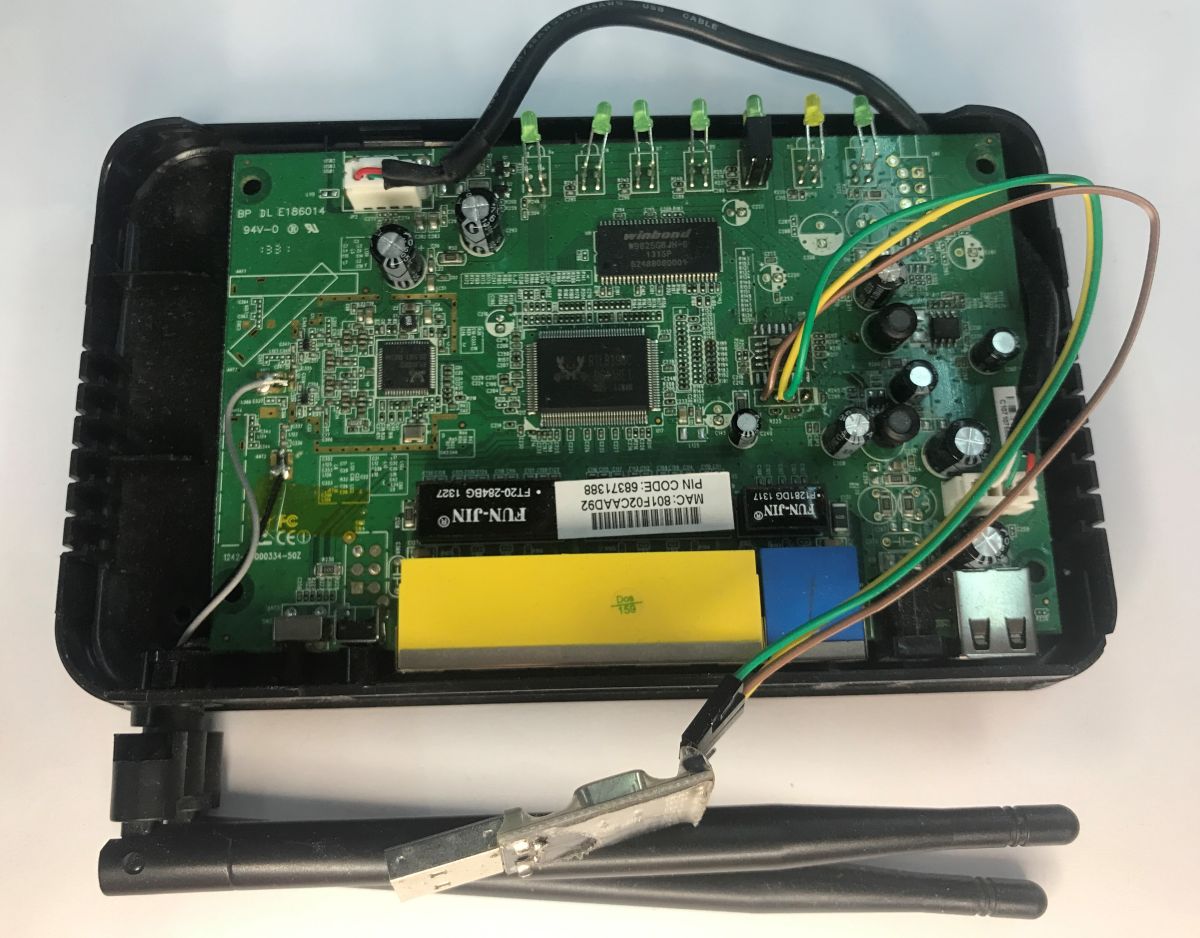
In the previous post, I showed the inside of the Cyfrowy Polsat LT-6408n router. I established that it is based on the RTL8196C chip, whose bootloader offers a simple command line along with the ability to load any machine code into RAM. Here, I’ll try to make use of this – I’ll start by loading simple instructions written by hand in hexadecimal notation, and then I’ll run a compiler and develop my own ‘flasher’, turning the old router into a sort of Arduino.
Previous post in the series: Analysis of the router’s internals, memory dump, bootloader, custom UART programme
A few words on the RTL8196C architecture
In the previous post, it was easy to see that the router in question is based on the RTL8196C. The RTL8196C is a very popular, highly integrated SoC (System on a Chip) from Realtek, forming the heart of many budget networking devices on the market. Under the bonnet lies a tried-and-tested 32-bit MIPS architecture processor core (typically clocked at around 400 MHz). As befits a dedicated networking chip, this processor is surrounded by a range of hardware features – these include, amongst others, a built-in 5-port Fast Ethernet switch (10/100 Mbps), a PCIe interface (often used for Wi-Fi modules), SDRAM and SPI Flash memory controllers, as well as a suite of basic peripherals, such as GPIO pins and a UART controller. It is thanks to this latter interface and the specific nature of the bootloader here that we’ll be able to start our programming experiments without having to desolder the memory or use an external programmer.
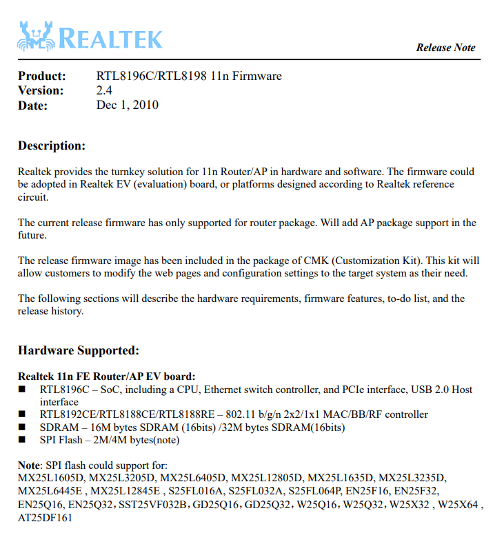
What makes this particularly interesting is that we also have register documentation, although I must admit that… when I first started writing this post, I wasn’t aware of this and was experimenting without full knowledge of the subject.

Commands used
Fortunately, we don’t need to program the Flash memory directly; this time, my tried-and-tested CH341 can stay in the drawer. The commands available from the bootloader allow us to load the programme into RAM and execute it from there. These include:
| Command | Syntax | Description of operation |
| EW | EW <address> <word1> [word2] ... | Writing 32-bit words directly to memory at the specified address. |
| DW | DW <address> <quantity> | Dump of 32-bit words from memory – useful for verifying the upload. |
| J | J <address> | Jump to the specified address – triggers the execution of the loaded code. |
The loading procedure is simple – we send words to the selected memory location via EW, confirm the write via DW, and execute the J jump.
The first programme written without a compiler
We’re starting from scratch. The programme must be written in machine code. We know that the RTL is based on the MIPS RLX4181 core. We can therefore use the basic instructions of this assembler to write, for example, a loop that sends an exclamation mark ‘!’ to the UART transmit port. I managed to determine its address by searching through the source code of similar Realtek chips:
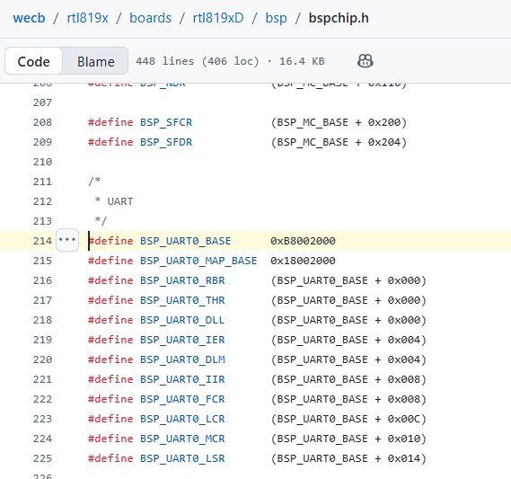
It is located at address 0xB8002000. The transmission of each character will be interspersed with an empty loop (delay) to prevent the transmit buffer from overflowing. You can make use of the documentation and online tools, for example the MIPS converter .
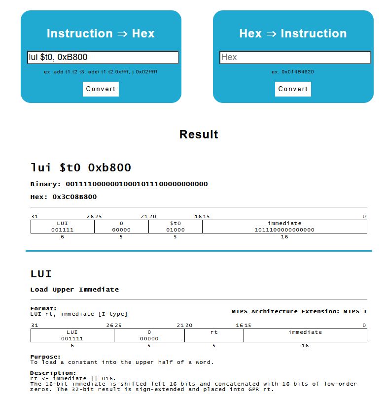
The code itself boils down to a few simple assembly instructions: loading the target UART address, writing a single byte (an exclamation mark in ASCII) to it, counting down the time in an empty loop (to allow the hardware time to ‘push’ the character out) and finally – performing an unconditional jump back to the start.
As a result, we obtain the following programme:
| Address | Hex | Instruction | Description |
| 80500000 | 3C08B800 | lui $t0, 0xB800 | Load the upper 16 bits of the UART base address |
| 80500004 | 35082000 | ori $t0, $t0, 0x2000 | $t0 = 0xB8002000 (UART THR transmit register) |
| 80500008 | 34090021 | ori $t1, $zero, 0x21 | $t1 = '!' (ASCII 0x21) |
| 8050000C | A1090000 | sb $t1, 0($t0) | Write the character '!' to the UART transmission register |
| 80500010 | 340A8000 | ori $t2, $zero, 0x8000 | $t2 = 32768 (delay counter) |
| 80500014 | 1540FFFF | bne $t2, $zero, delay | If the counter ≠ 0, jump back to the loop |
| 80500018 | 214AFFFF | addi $t2, $t2, -1 | Decrement the counter by 1 (delay slot) |
| 8050001C | 08140002 | j 0x80500008 | Jump back to the start of the loop |
| 80500020 | 00000000 | nop | No operation (delay slot) |
After interrupting the bootloader, we load this code (hexadecimal, word by word) using the command EW :
EW 80500000 3C08B800 35082000 34090021 A1090000 340A8000 1540FFFF 214AFFFF 08140002
EW 80500020 00000000
The results can be verified using the command DW 80500000 9.
We execute the code with a jump:
J 80500000
The result is that the terminal window is immediately flooded with an infinite string of exclamation marks, "!!!!".
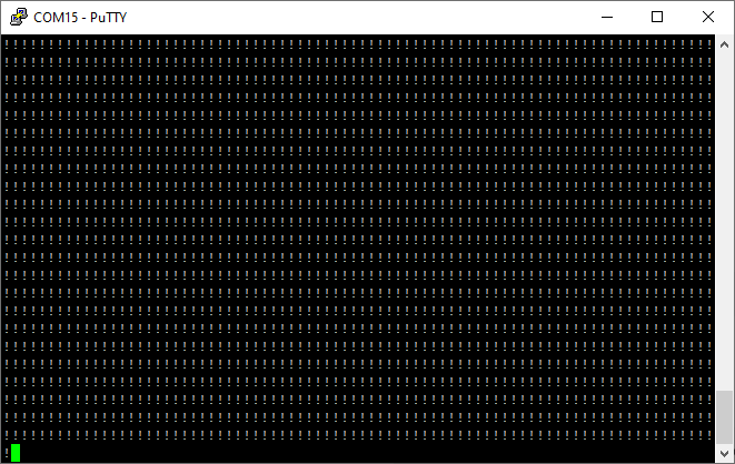
The proof of concept works, but who would want to write machine code by hand?
Compiler and the C language
Writing MIPS instructions by hand and converting them to hexadecimal using a hex converter is a tedious process. To To create more complex programmes, I decided to use a suitably selected compiler, compatible with the processor in use – mips-linux-gnu-gcc . This allows me to write programmes in C. I couldn’t get it to run on Windows, so I used a Linux environment on ‘Windows’ - WSL. I didn’t have any header files for this Realtek chip, but I don’t need them anyway. I started with the simplest piece of code I wanted to compile:
Code: C / C++
This code now needs to be compiled. I run mips-linux-gnu-gcc with the following parameters:
- -march=mips32 – generate code for the MIPS32 architecture (compatible with the RTL8196C core)
- -mno-abicalls -fno-pic – disable position-independent code (PIC) – the programme runs at a fixed address
- -nostdlib -nostartfiles – do not link the standard C library or the default start-up code
- -ffreestanding – do not assume the presence of a standard runtime environment
- -O2 – optimisation – smaller and more efficient machine code
- -T rtl8196c.ld – use a custom linker script defining the memory layout (described below)
The compiler generates an ELF file, from which a raw binary file – the machine code itself, without headers, ready to be loaded directly into RAM – is extracted using ‘mips-linux-gnu-objcopy -O binary’.
The key element is the rtl8196c.ld linker script, which tells the compiler at which address in RAM our programme will ultimately be located:
Code: C / C++
The compilation script (apologies for the image format, but the forum engine won’t let me paste these commands...):
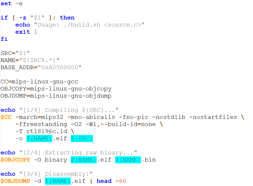
The second stage is to export the commands from the binary file into a readable text format that can be pasted into Realtek. This isn’t normally done, so I used my own Python script:
Code: Python
Generated commands:
EW A0500000 3C05A050 24A50050 3C04B800 3C06001E 24020048 00A01825 304200FF 24630001
EW A0500020 A0822000 80620000 1440FFFC 304200FF 34C28480 00000000 2442FFFF 1440FFFD
EW A0500040 00000000 1000FFF3 24020048 00000000 4865792E 2E0D0A00 00000000 00000000

DW A0500000 24
J A0500000
Result:
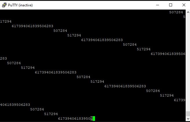
The programme works, although this time the result was slightly worse – characters are getting lost; I suspect my loop waiting for the UART to become available didn’t work.
My own batch upload tool
The instructions are already generated automatically; they just need to be uploaded automatically. Command-line mode is enabled by pressing ESCAPE during boot-up; after all, a programme can do this. The programme can also send commands. We just need to determine when the router starts up – its start-up message can be intercepted. We can then send individual ‘EW’ commands one by one, verifying them with the ‘DW’ command. This is precisely the process carried out by the Python script I’ve refined (‘uart_auto_flash.py’). It operates in a simple loop: it listens for the “Booting” message, automatically presses the ESC key to enter command-line mode, and then sends byte packets to the console, taken directly from the compiled binary file ('.bin'), verifying the correctness of the operation after each block with the ‘DW’ command. This allows the process to be fully automated without the tedious copying and pasting of instructions into the terminal window.
The only thing still missing was automatic rebooting. Ideally, the reboot could be triggered by the DTR/RTS pin from a suitable USB-to-UART converter, but as I didn’t have one to hand at the time, I used... a power socket with Tasmota firmware. I control it via the classic REST API for commands; OpenBeken also supports this standard.
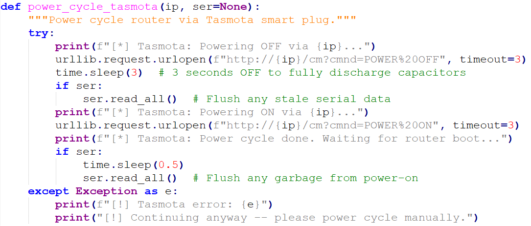
In this way, uploading the test programme to the router simply comes down to executing a single command:
python ..\uart_auto_flash.py hello_world.bin --tasmota 192.168.0.176
GPIO support and necessary fixes
The next thing I tried to get working was the classic LED flashing. The LAN port status LEDs are connected directly to the Realtek pins, so there is potential to control them. They are described, for example, as LED_PORT1/GPIOB3, which suggests they have a dual role – either taken over by the Ethernet controller or operating in generic, programmable I/O mode.
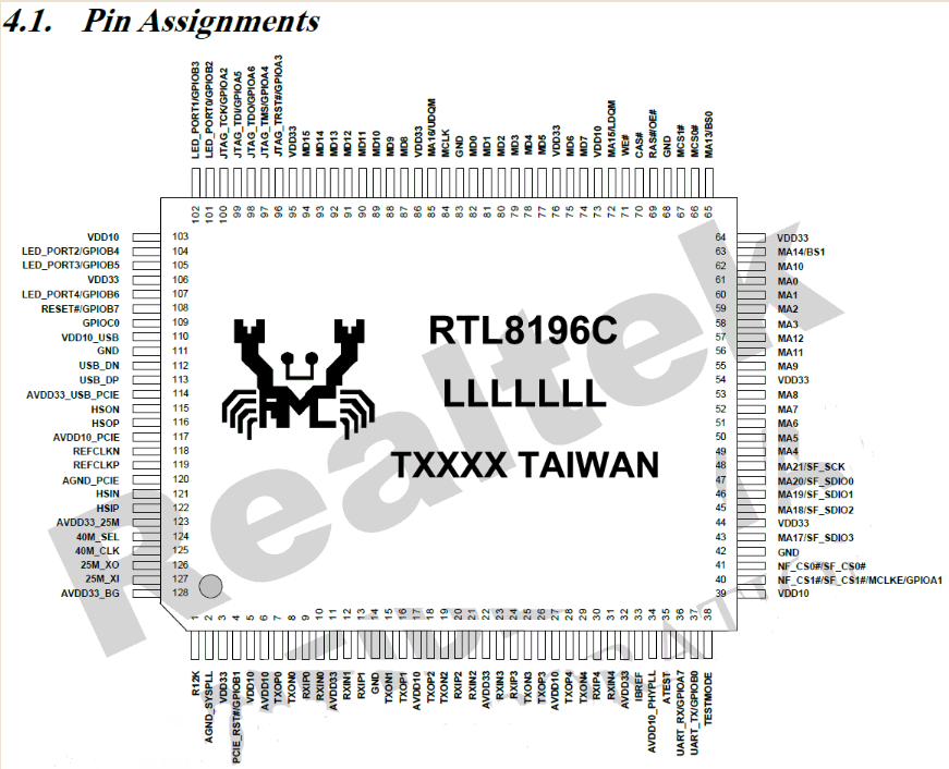
However, I quickly ran into a few problems. The programme would actually freeze on the very first loop and behave unpredictably. Through trial and error, I worked out what I needed to fix.
Firstly, I had to set the stack pointer. In bare code executed directly from the bootloader, the ‘$sp’ pointer may point to ‘garbage’ or to an area used by the bootloader itself. Any attempt to execute more complex C code, such as using local variables or calling subsequent functions (‘uart_print’), resulted in important data being overwritten and the processor immediately freezing. The stack pointer had to be manually set to a safe area of RAM (e.g. ‘0xA0600000’).
Secondly, I had to disable interrupts. The bootloader leaves them enabled, and since we are running our bare-metal programme without handling them, any asynchronous signal (e.g. from the system timer or network interface) would cause the programme to go haywire and the hardware to freeze. I had to insert an instruction to disable interrupts in coprocessor 0 (CP0).
Thirdly, and most importantly – the GPIO initially did not work because it was configured for a purpose other than digital input/output (Pin Muxing). Instructions to write to the standard I/O port control registers were completely ignored. The pins on the RTL8196C have shared functions, and the LEDs are, by default, connected directly to the hardware Ethernet switch controller (the so-called ‘hardware LED controller’). Until we physically switch the pin to GPIO mode in the controller configuration, any changes to the port states will have no effect. After a rather painstaking search and analysis, I located the relevant, undocumented hardware register responsible for pin multiplexing – ‘PIN_MUX_SEL’ at address ‘0xB8000040’. Switching the bits for the relevant ports to programmable mode (whilst taking care not to disable the UART!) ultimately allowed me to take full control of them.
Here is the final, working code to control the LEDs:
Code: C / C++
Result:
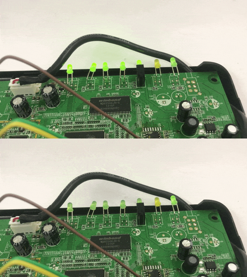
Countdown via UART and finalisation
The next thing I wanted to try was displaying numbers via UART. To start with, something simple – a countdown of some sort. I decided on a simple method of converting an integer to a string:
Code: C / C++
Unexpectedly, however, the programme then stopped working. I realised that I’d forgotten to specify the start function’s entry point in the linker, which meant that the Realtek bootloader wasn’t jumping to the right place. I had to add the entry ‘z entry’ at the very top of the linker configuration and then include that identifier in the C code:
Code: C / C++
The rest of the code works as expected – the main loop now has a counter and displays it with each message. There is no
sprintffunction; I display the static string separately and the number converted to a string separately.
Code: C / C++
Result:
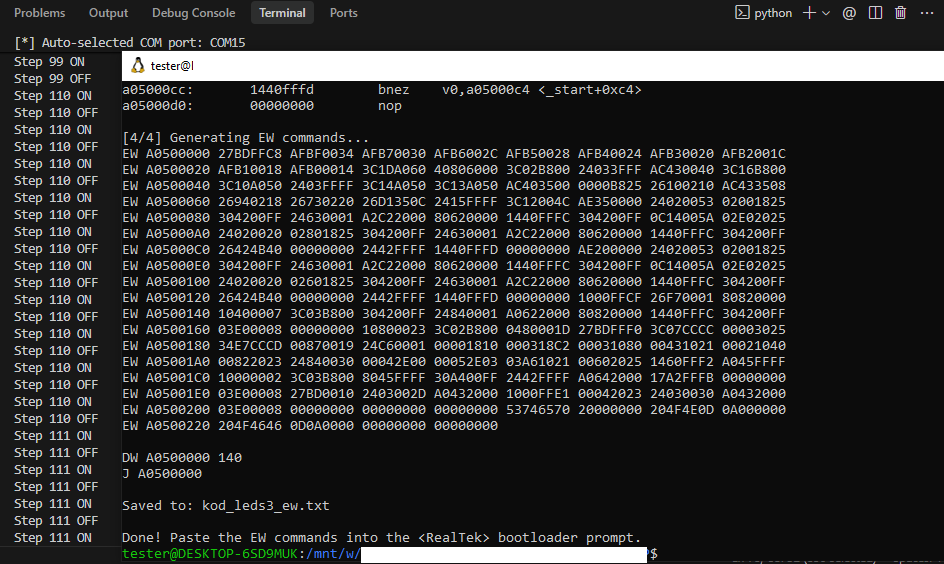
Summary
In this way, I managed to set up a basic working environment for the RTL8196C. I began my experiments with simple instructions, which can be written by hand or with the help of a suitable online tool; I then found a suitable compiler and, starting from scratch, prepared my own linker script and C boot code for it. I resolved issues with unwanted interrupts, the stack and pin multiplexing, and automated the entire flashing process in Python. In doing so, I transformed an old router into a convenient development platform on which I can run my own machine code. Feel free to join the discussion – perhaps some of you have tried similar experiments with other SoCs?
PS: This isn’t the last post in this series, and there are still issues to resolve in my overall workflow – I tried to create a simple console for this router, but for some unknown reason the programme would freeze after processing just a few characters. Once I’ve sorted that out, I’ll show you a more complex project based on this Realtek chip.

p.kaczmarek2 wrote 14734 posts with
rating 12817 , helped 659 times.
Been with us since 2014 year.
Comments