







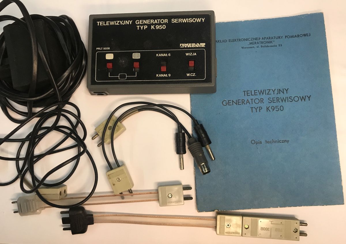
Join me on a journey back in time to 1985, where I’ll be presenting a complete set of the MeraTronik K950 TV service generator, complete with full documentation and the original warranty. A TV service generator is a device used to generate test signals for black-and-white and colour television sets. These signals allow for the convenient testing and tuning of the television’s entire signal path – from the channel selector, through the IF and video amplifiers, right up to the synchronisation, deflection and high-voltage stabilisation circuits, as well as the precise adjustment of the picture and convergence on the picture tube.
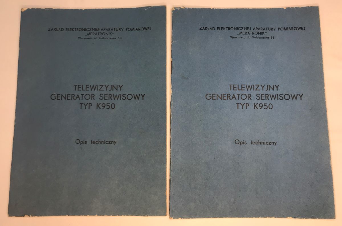
Let’s start, however, as one should in theory – with the manual. From my own experience, I know that many people aren’t patient enough and tend to dive straight into the equipment, but really, it’s worth knowing what you’re doing, and the manual shown here is a world away from what you get with modern products. Actually, it should be in the plural here – yes, there are two copies of the Technical Description. Those were the days when you could simply search online for...
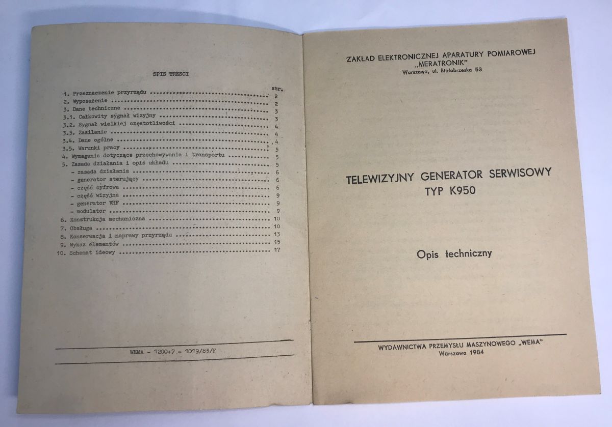
The booklet dates from 1984 and was published by the ‘Wema’ Machine Industry Publishing House. It opens with a table of contents that already hints at the quality of the documentation.
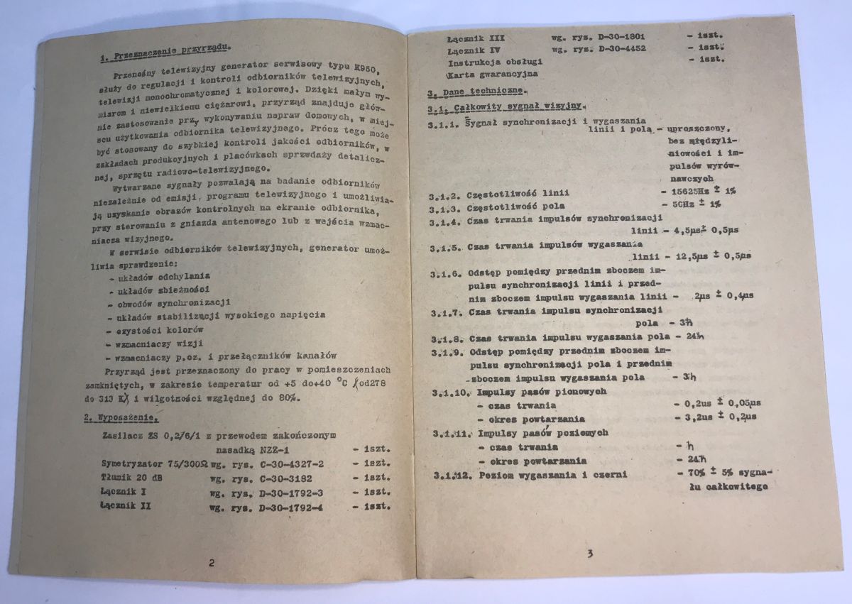
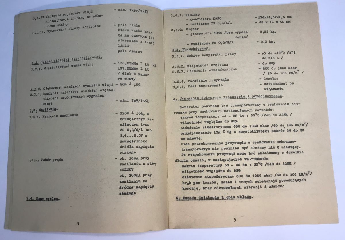
It begins with a description of the instrument’s intended use and the contents of the kit. This is followed by the device’s technical specifications, a description of the signal it generates, and detailed time-domain and amplitude waveforms.
The next page continues this description, followed by recommendations regarding the transport and storage of the device. Well, it is quite detailed – but that is not the most impressive part yet.
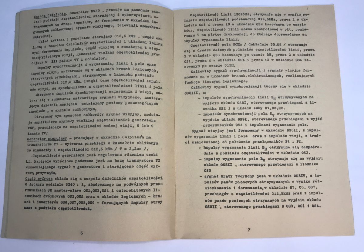
Next, we have a detailed technical description of how the entire device works, broken down into individual functional blocks.
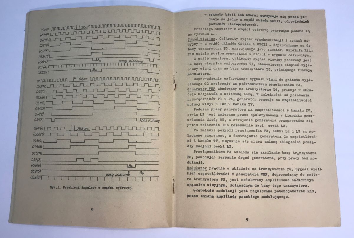
One of the pages in the description is devoted to a diagram of the pulse waveforms in the digital section, which makes it easier to diagnose the equipment.
A description of the electronics is one thing, but I certainly wouldn’t have expected a detailed layout of the PCB itself here:
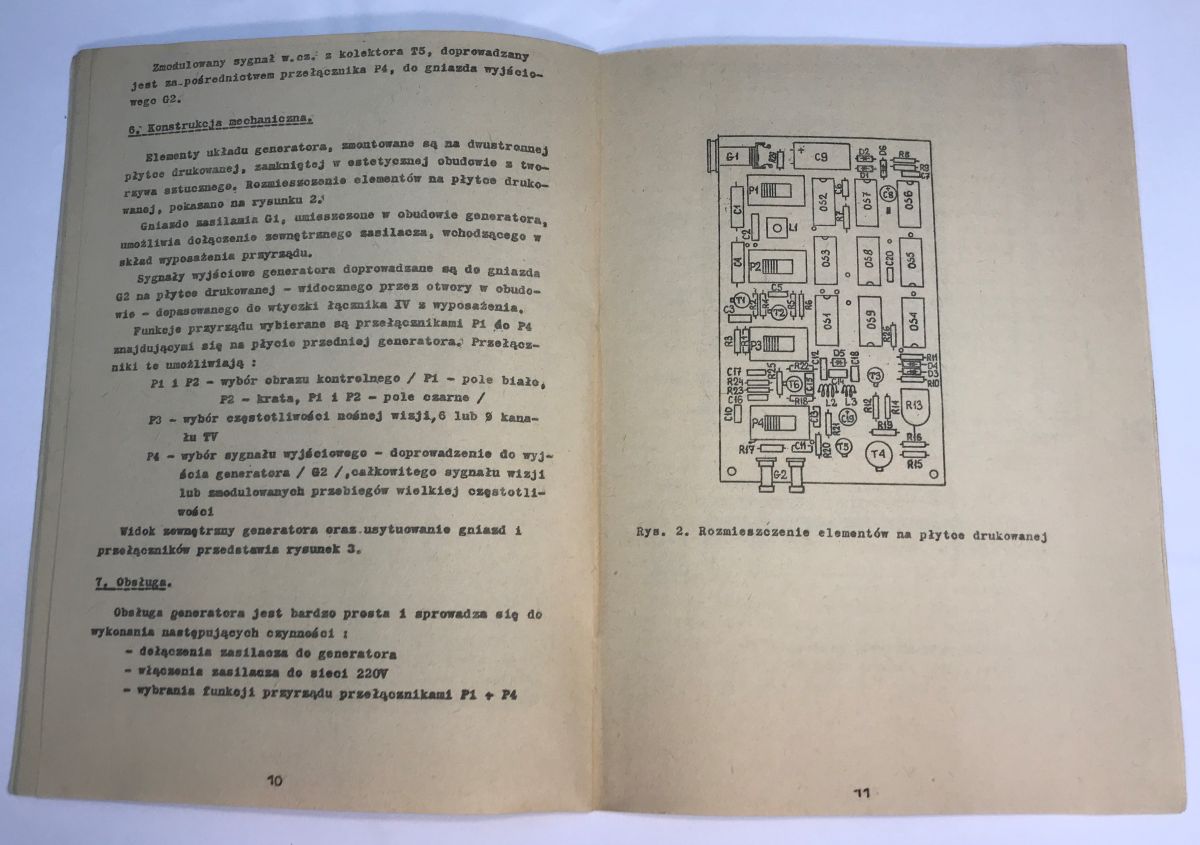
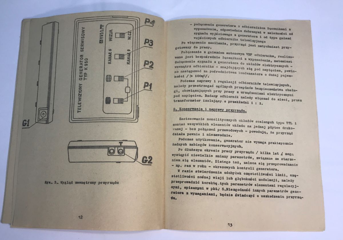
Moving on, after the components have been laid out on the PCB, there is also a diagram of the instrument’s casing, showing views from three sides. Next comes a section on the maintenance of the device. It is clear that the whole unit has been designed with longevity in mind.
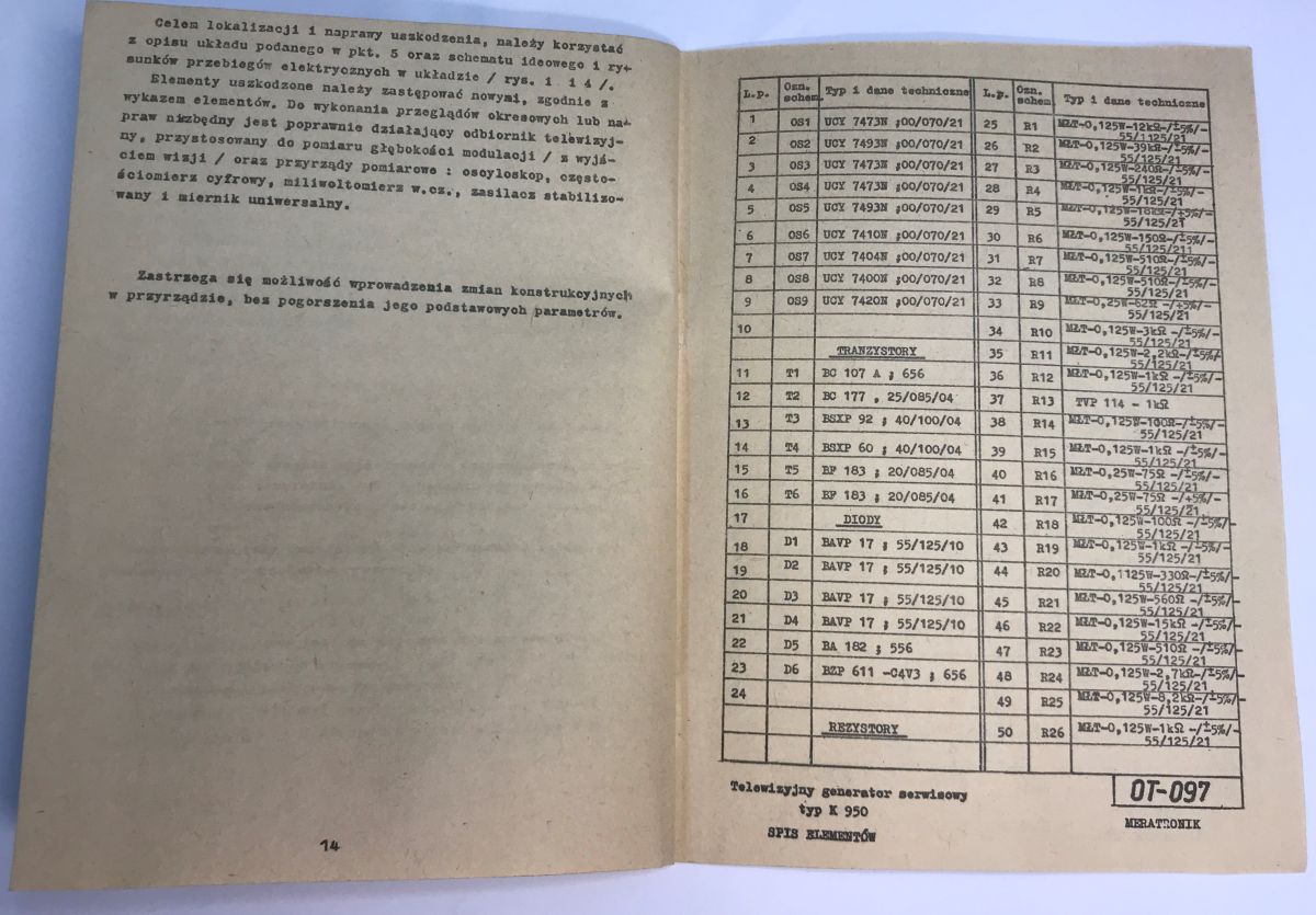
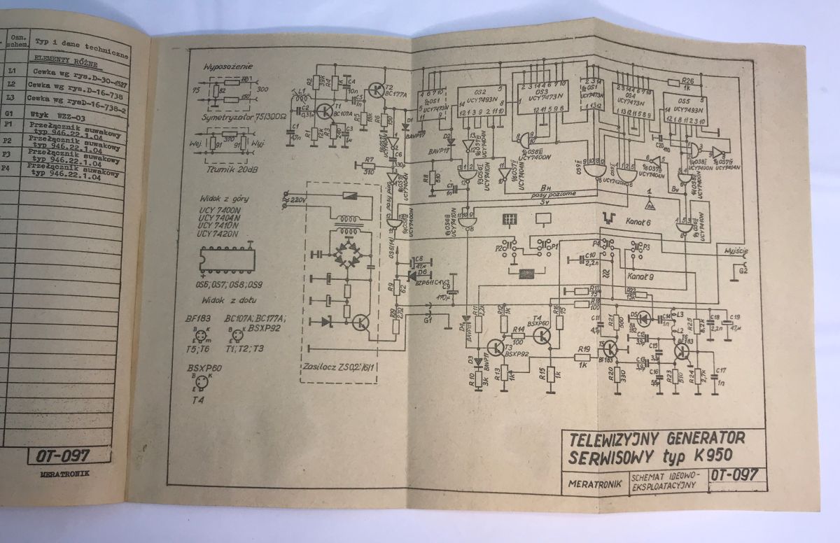
Finally, there are a few words on servicing the device itself, along with a detailed list of components and their designations. On the last page, there is a fold-out diagram.
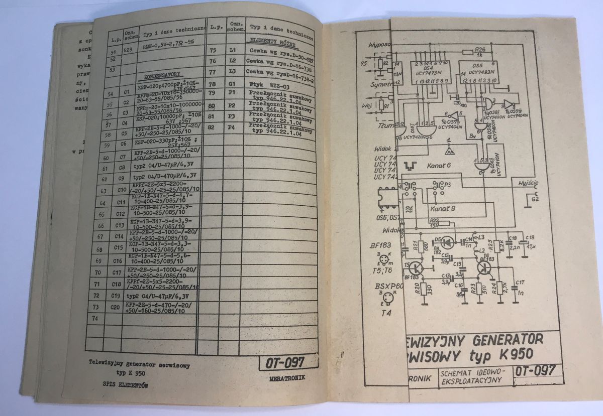
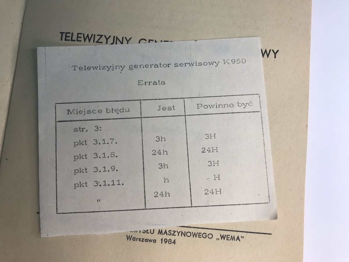
Actually, there was one more slip of paper in the manual – an errata sheet, no doubt cut out by hand. The attention to detail in the documentation is impressive.
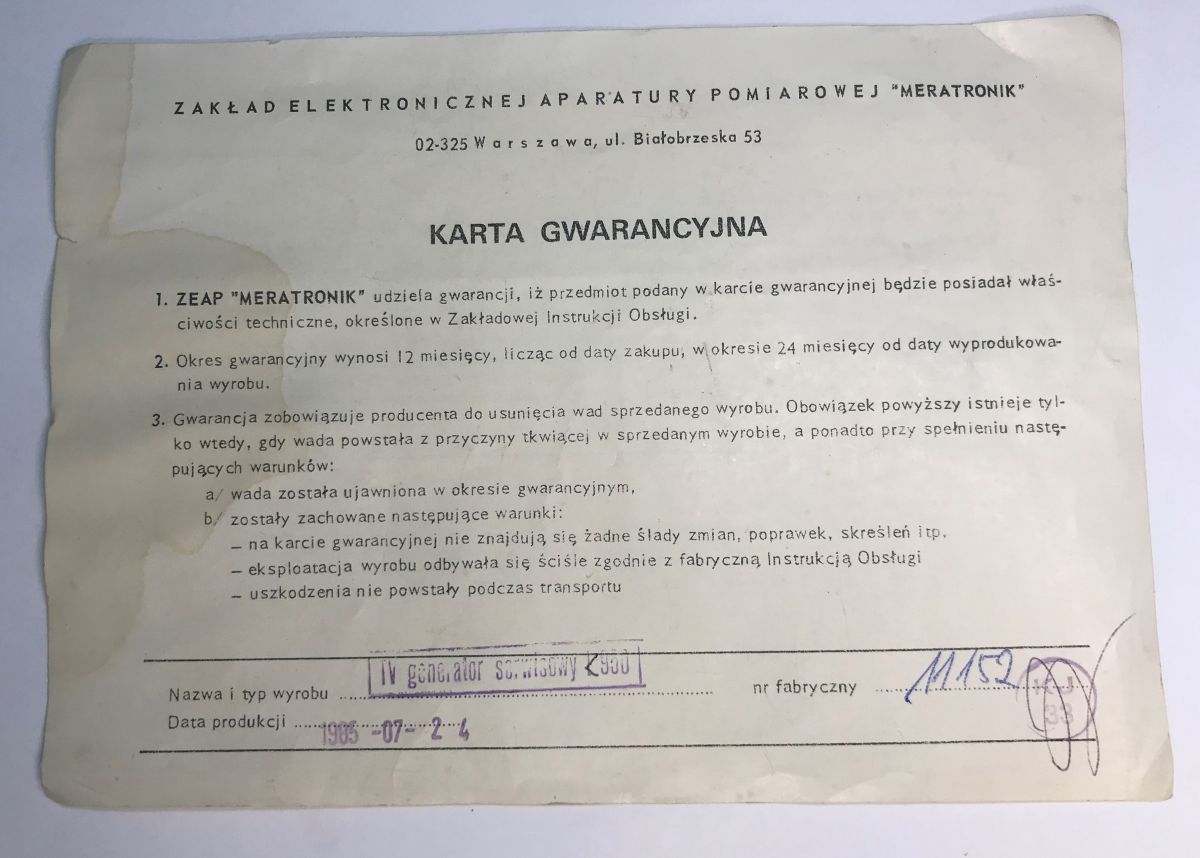
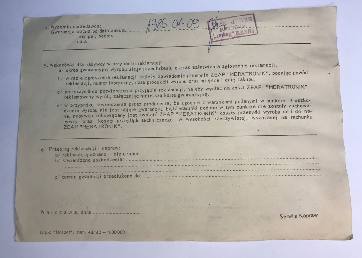
And then there’s the formalities – the warranty, complete with a stamp, valid for 12 months. It expired about 40 years ago.
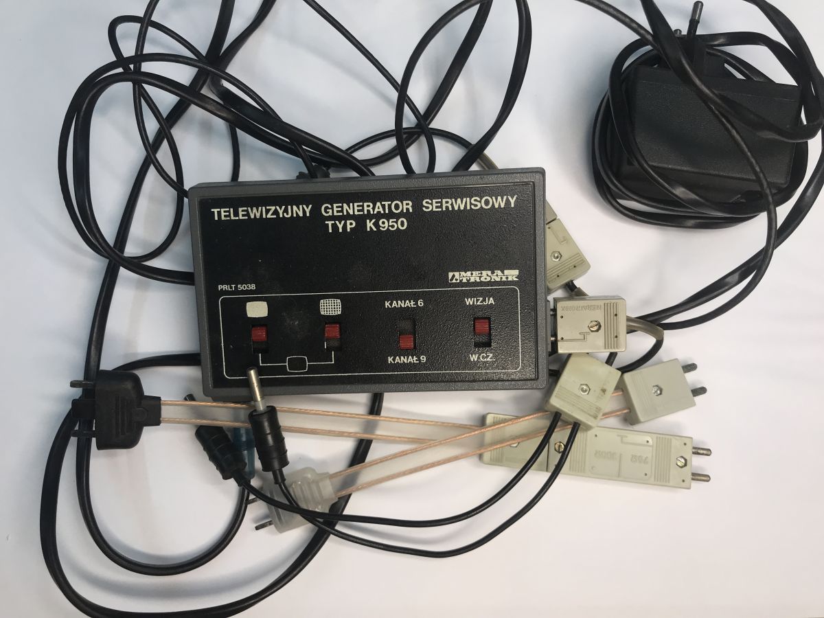
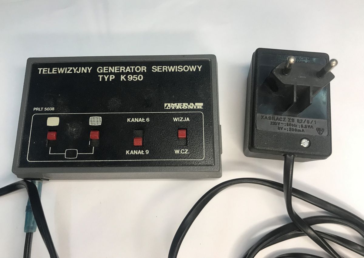
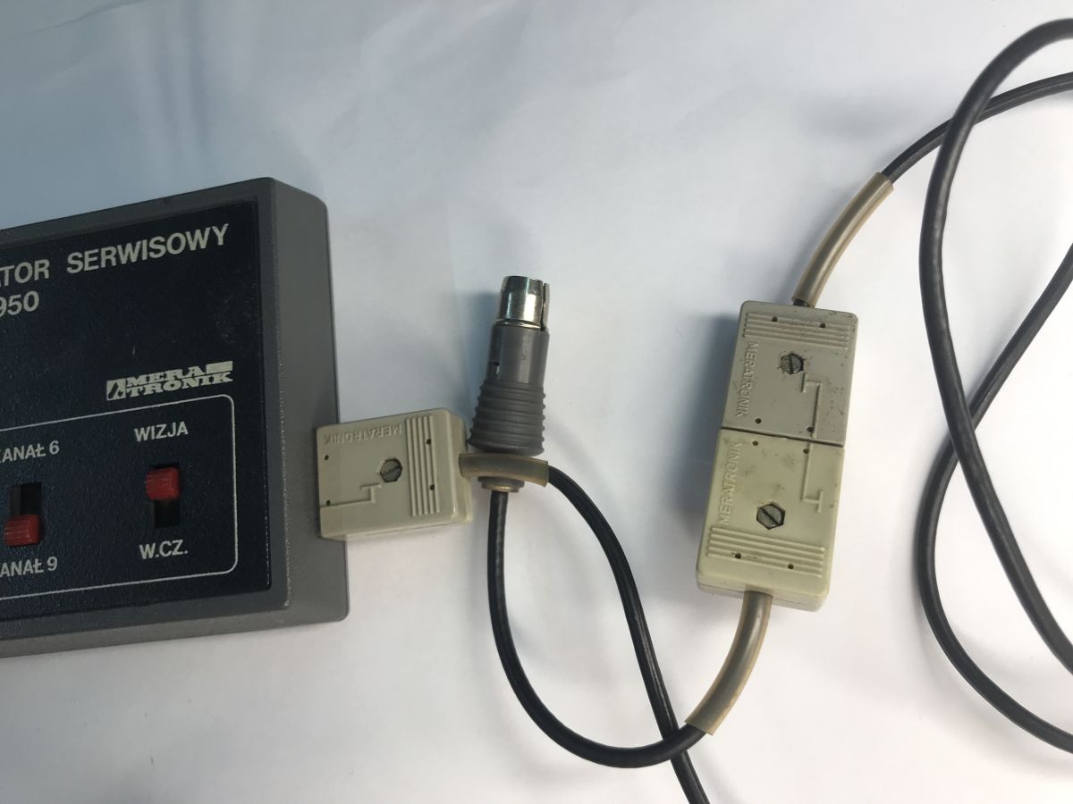
That leaves the unit itself – complete with a power supply (based on a mains transformer, of course, not a switching power supply) and a range of cables:
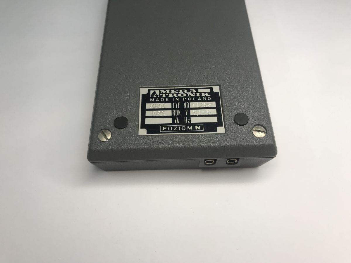
On the back of the unit there is a plate showing the date of manufacture and a specific serial number.
Once the casing has been removed, we can see a double-sided, tinned board:
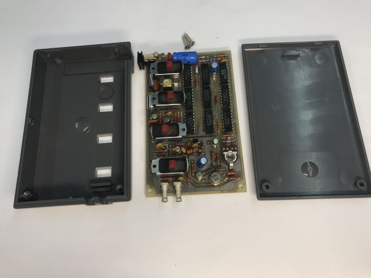
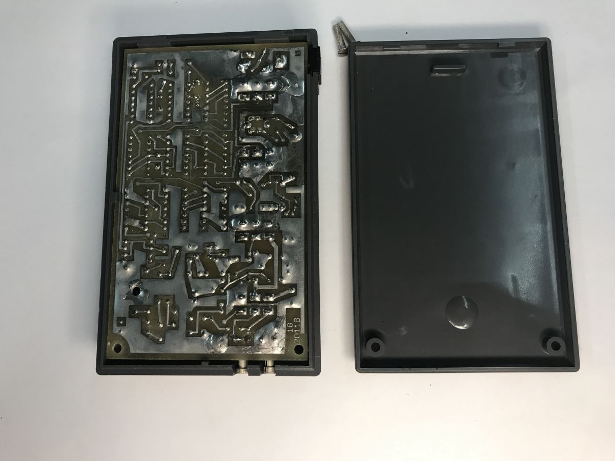
The device consists of separate sections; first comes the 312.5 kHz control generator, the signal is processed by the digital section, which includes a set of frequency dividers and pulse-shaping circuits, the video section (with a summing circuit and video output stage), and a frequency generator operating in TV Band III, along with an optional modulator.
In addition, there are four switches available, which allow you to:
- select the test pattern – white field/checkerboard/black field
- select the carrier frequency – channel 6 or 9
- select the output signal – modulated or unmodulated
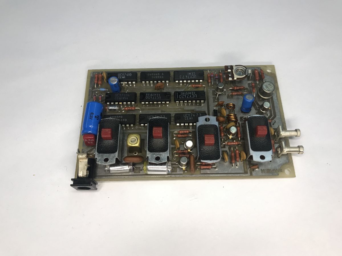
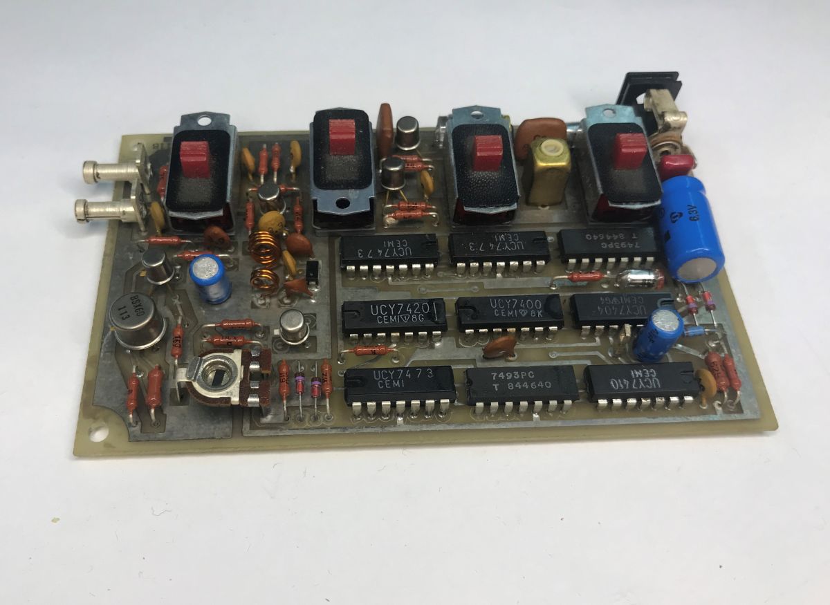
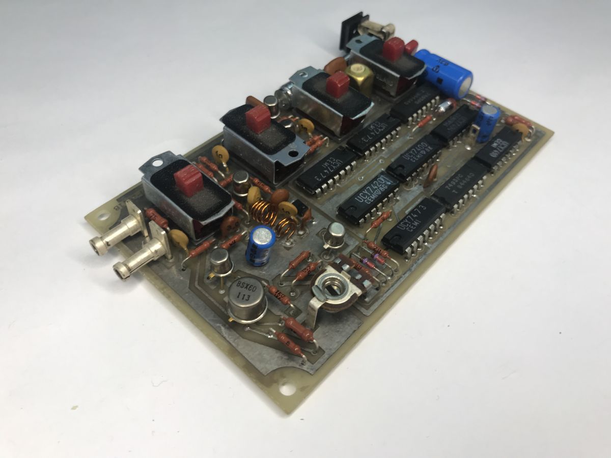
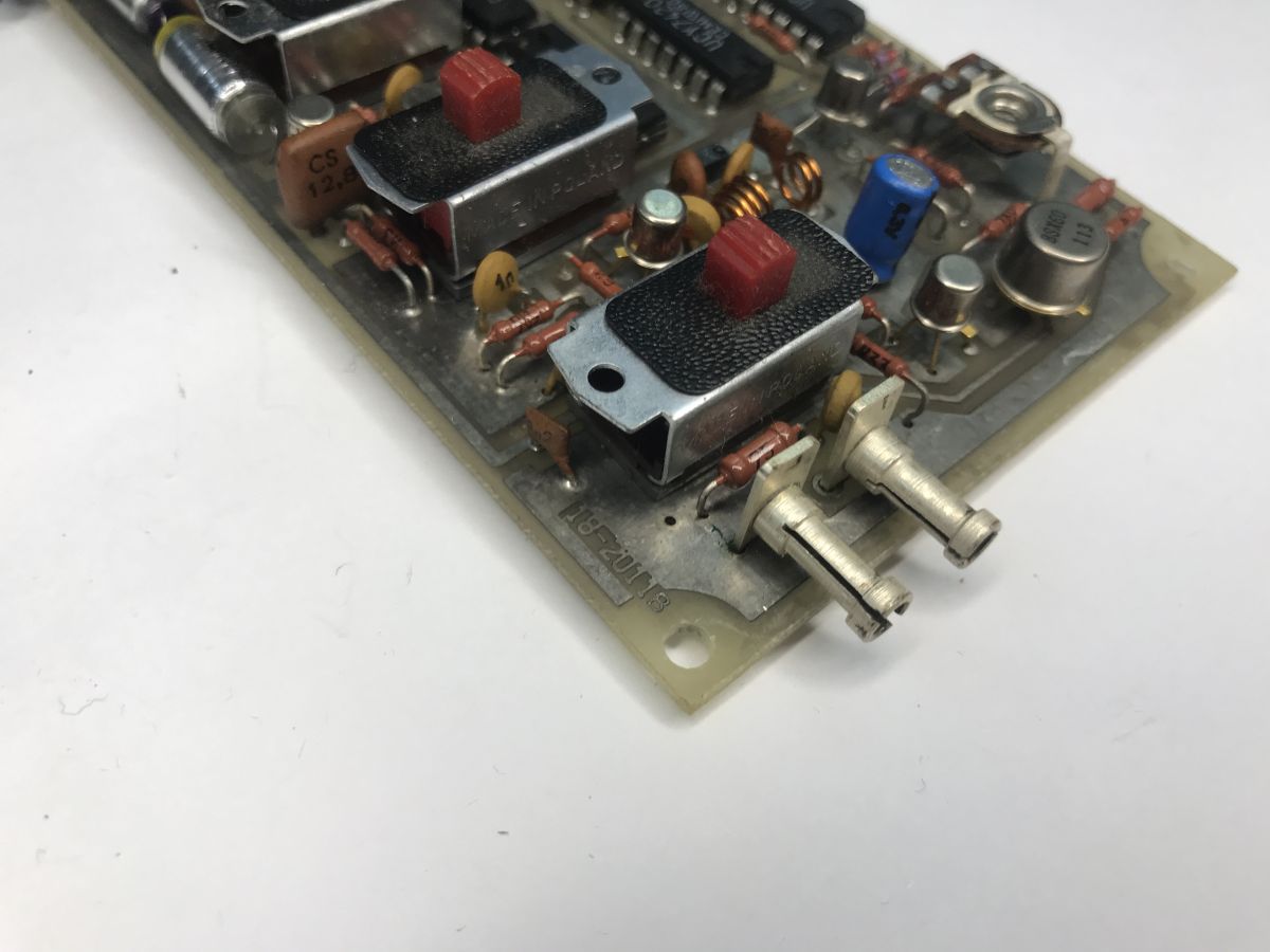
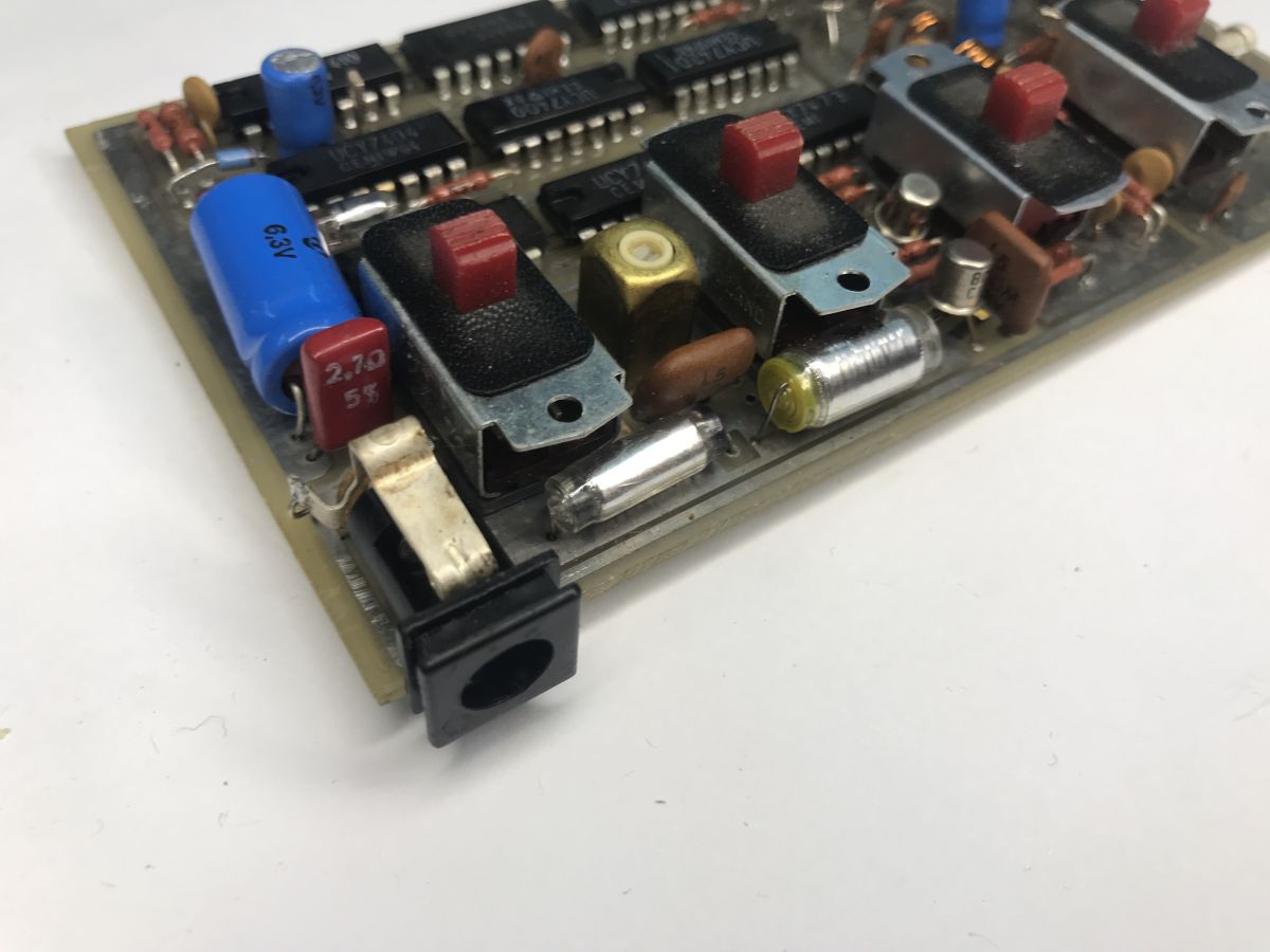
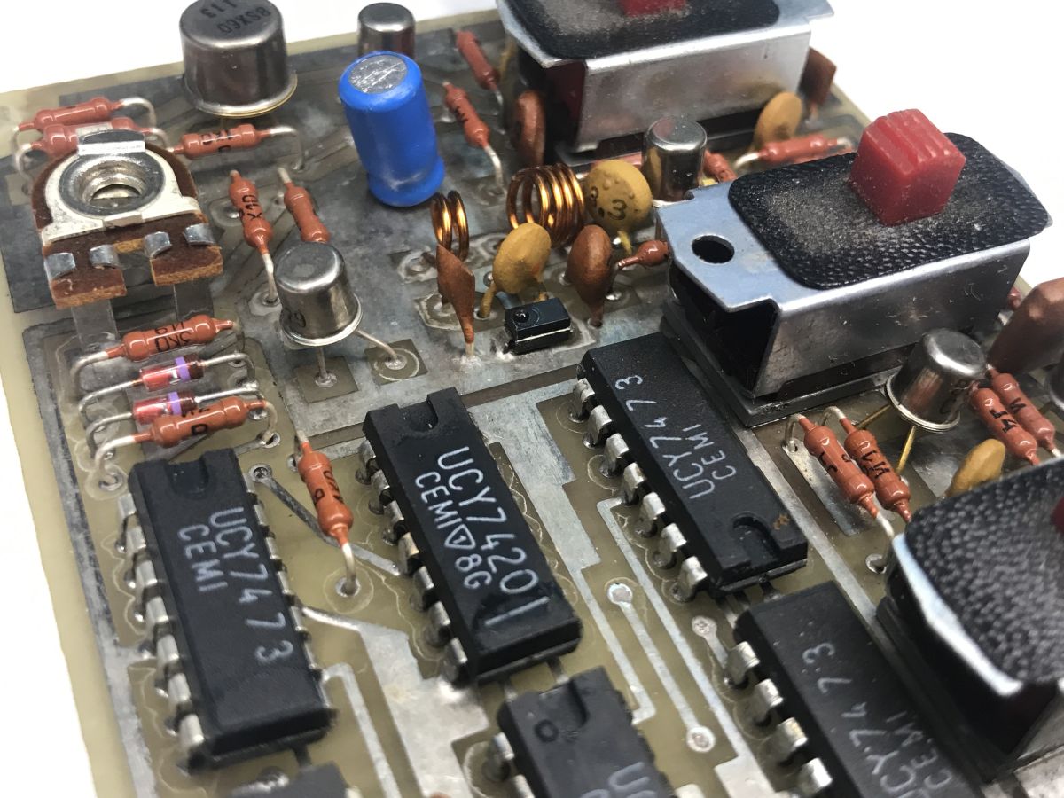
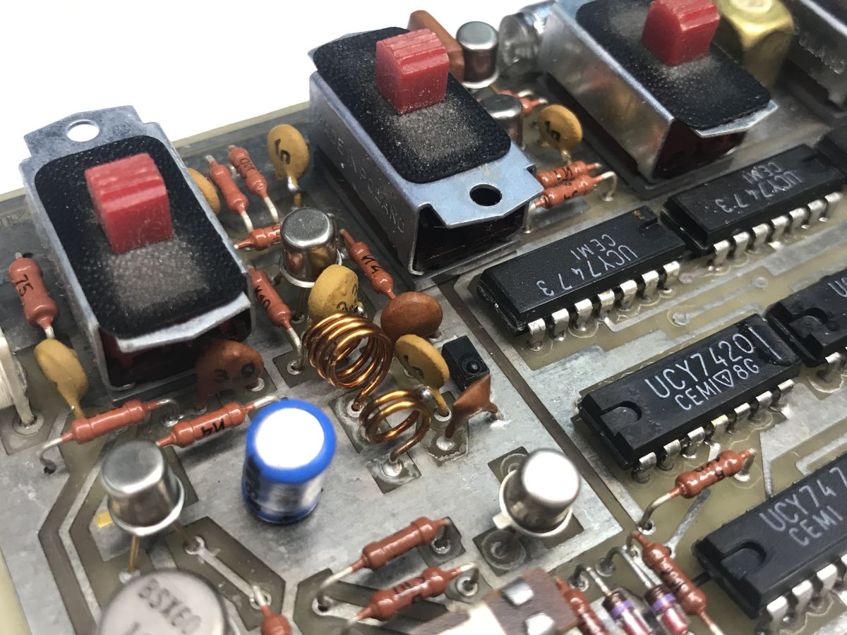
Essentially, I will repeat the documentation here, but the device consists of components such as:
- UCY7400 (NAND gates, e.g. the main control generator)
- UCY7404 (hex inverter)
- UCY7410 (triple 3-input NAND gate)
- UCY7420 (dual 4-input NAND gate)
- UCY7473 (dual J-K flip-flops, frequency divider unit)
- UCY7493 (4-bit binary counter / frequency divider)
- BC107A (NPN medium-frequency transistor)
- BC177 (PNP medium-frequency transistor)
- BSXP60 (NPN switching transistor)
- BSXP92 (NPN switching transistor)
- BF183 (NPN high-frequency transistor)
Finally, it would be worth showing the test patterns generated on the TV. I’ll refer here to a video from the internet – I haven’t yet had the chance to test this myself: https://www.youtube.com/watch?v=1TBGNQF4zkM
To sum up, this was a fine piece of Polish electronics repair history. The equipment is a good 40 years old and was made before I was even on the horizon. What impresses me most about it is the documentation; it’s not just a circuit diagram or a list of components – the whole thing has been thought through in detail, and it’s clear that the device was manufactured with long-term use in mind. There’s no sense here of that mentality that it’s better to make a product that will break, because the customer will buy a replacement – those days are long gone. I suppose I don’t need to mention this here, but just for comparison’s sake, I’ll refer to a somewhat similar but modern device that I tested two years ago:
A TV from the rubbish heap, an LED tester, repairing the LED backlight on a zero budget
The contrast in approach is striking – here, full documentation in our native language; there, a single note in English with no information on the internal design...
The equipment featured in this thread was given to me by a reader, for which I am very grateful. Along with it, I also received some other equipment, which will come in handy for future presentations.
PS: In a separate thread, I’ll try to demonstrate this equipment in practice; I just need to find the time and energy to carry that one CRT upstairs, which I’ve got stashed away in the cellar...
Cool? Ranking DIY Helpful post? Buy me a coffee.

