






Retro features: the Polish UCY74xx series from CEMI – an overview of sample logic gates
TL;DR
- A practical overview of Polish CEMI UCY74xx TTL logic gates covers NAND, NOR, NOT, AND, and AND-OR-INVERT chips.
- Each circuit is explained with Boolean equations, truth tables, and button-driven video demos, including open-collector and buffered output variants.
- Examples include UCY7401, UCY7402, UCY7404, UCY7406, UCY7407, UCY7408, UCY7410, UCY7420, UCY7430, UCY7450, and UCY7451; UCY7406 can switch loads up to 30V.
- The demonstrations show LEDs responding exactly to the logic tables, such as a single button for UCY7402 and either button pair for UCY7450.
- The selection is not exhaustive, and more complex sequential and combinational UCY circuits are promised in a later post.
AI summary based on the discussion. May contain errors.
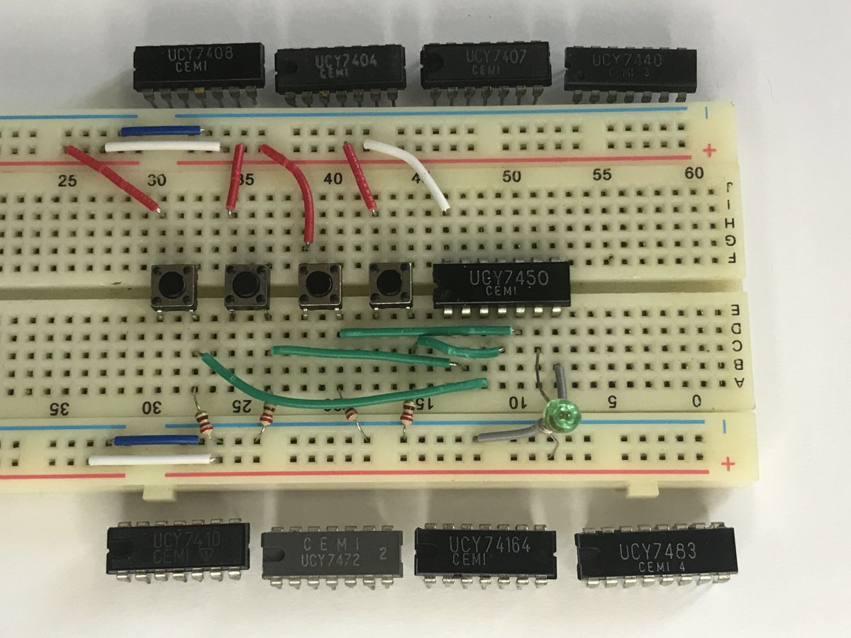
Here’s a brief practical overview of popular logic gates from the Polish UCY74xx series. I’ve focused here on providing a practical illustration of how each circuit works. Below you’ll find a discussion of classic chips implementing NAND, NOR, NOT and AND functions. I have described each gate using the relevant Boolean equation and truth table, and I have combined theory with practice using video recordings in which I demonstrate how these circuits respond to logic states triggered by buttons.
The original 7400 series, introduced into mass production by Texas Instruments, was one of the first digital integrated circuits manufactured using TTL technology. Over the years, these circuits have seen many versions, such as the high-speed (74S) and low-current (74LS) variants, as well as CMOS versions (the HC and HCT series). The specific letter designations depended on the version and manufacturer – for example, in Poland these chips were manufactured by CEMI under the name UCY. During the heyday of TTL technology, and thus at the turn of the 1970s and 1980s, this was the fundamental building block of digital electronic circuits.
UCY series circuits are available in versions with different output stage configurations. Alongside standard outputs, the list below also includes open-collector versions (allowing, amongst other things, the control of higher-voltage loads) and buffered versions (with increased current capacity, used to drive more demanding components).
The UCY7401 comprises four two-input open-collector NAND gates. These implement the negated logical product (NAND) function.
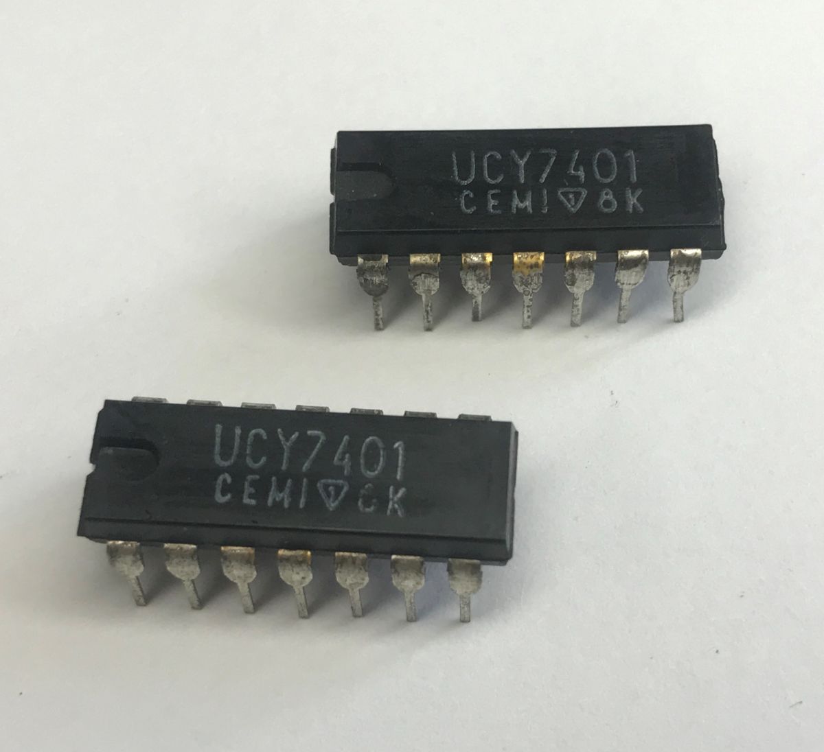
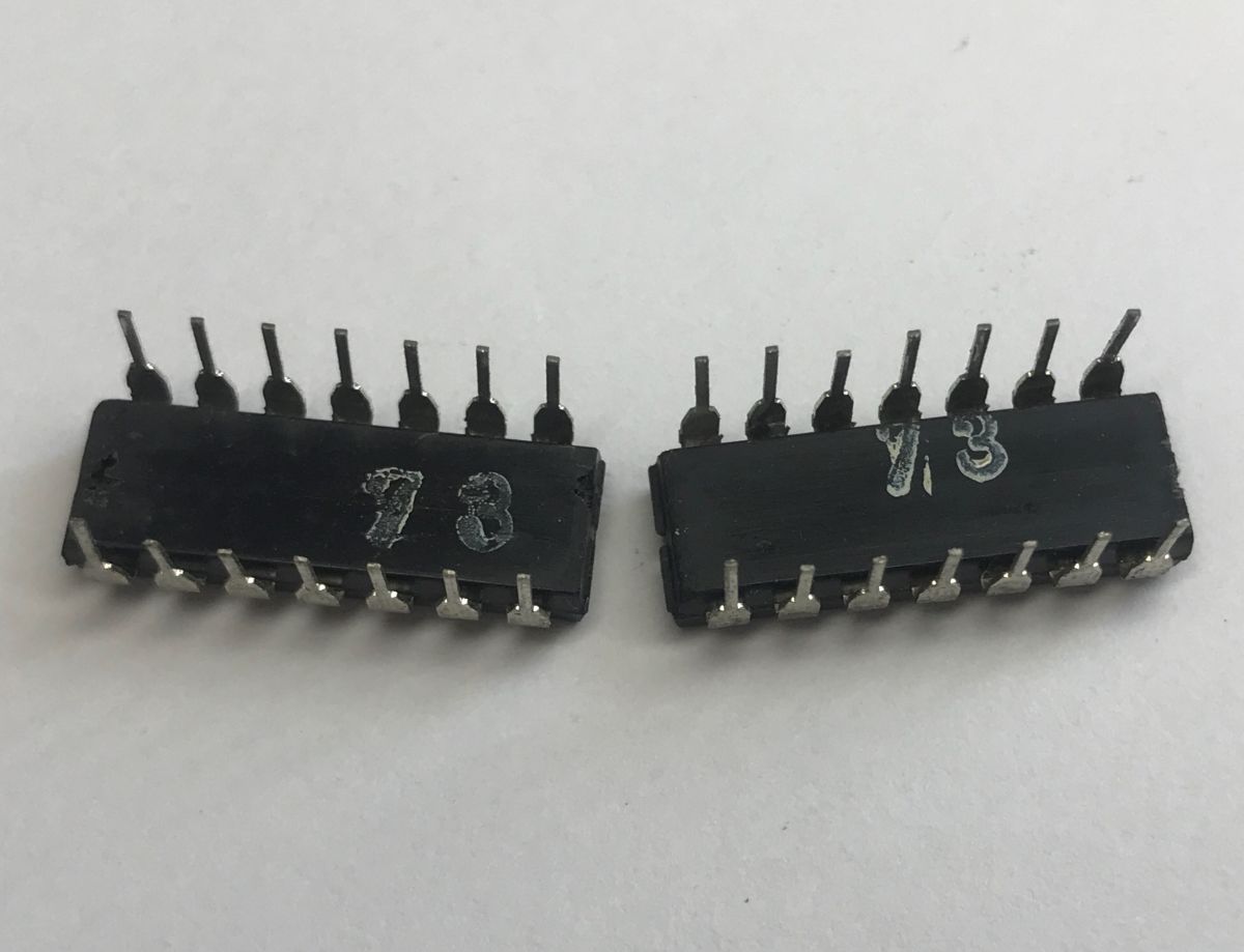
The function can be expressed by the formula:
$$Y = \overline{A \cdot B}$$
The truth table shows that the function returns a high level only when at least one of the inputs is at a low level:
| A | B | Y |
| 1 | 1 | 0 |
| 0 | X | 1 |
| X | 0 | 1 |
UCY7401 pinout:
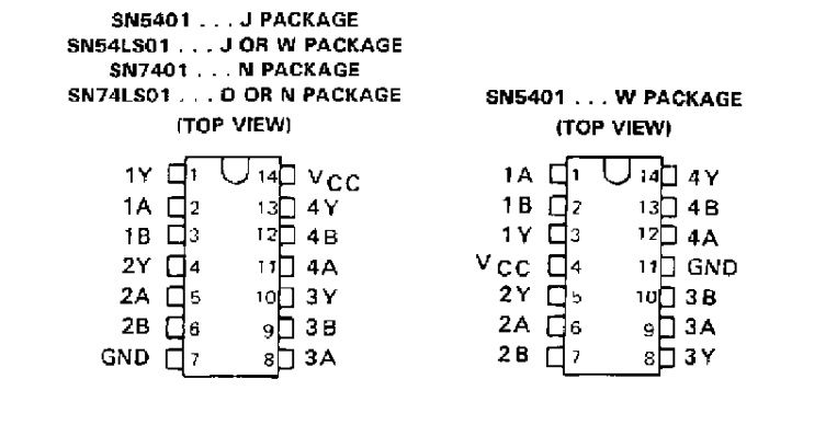
Video demonstration – the LED is connected between the output and the power supply, so when it lights up, this indicates a low state. For the sake of simplicity, I’ve connected the inputs to earth, even though with TTL this requires slightly lower resistor values and draws more current; however, I wanted pressing a button to indicate a high state. The video shows that the LED lights up only when both buttons are pressed.
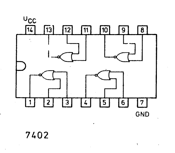
UCY7402 these are four two-input NOR gates. They implement the negated OR (NOR) logic function.
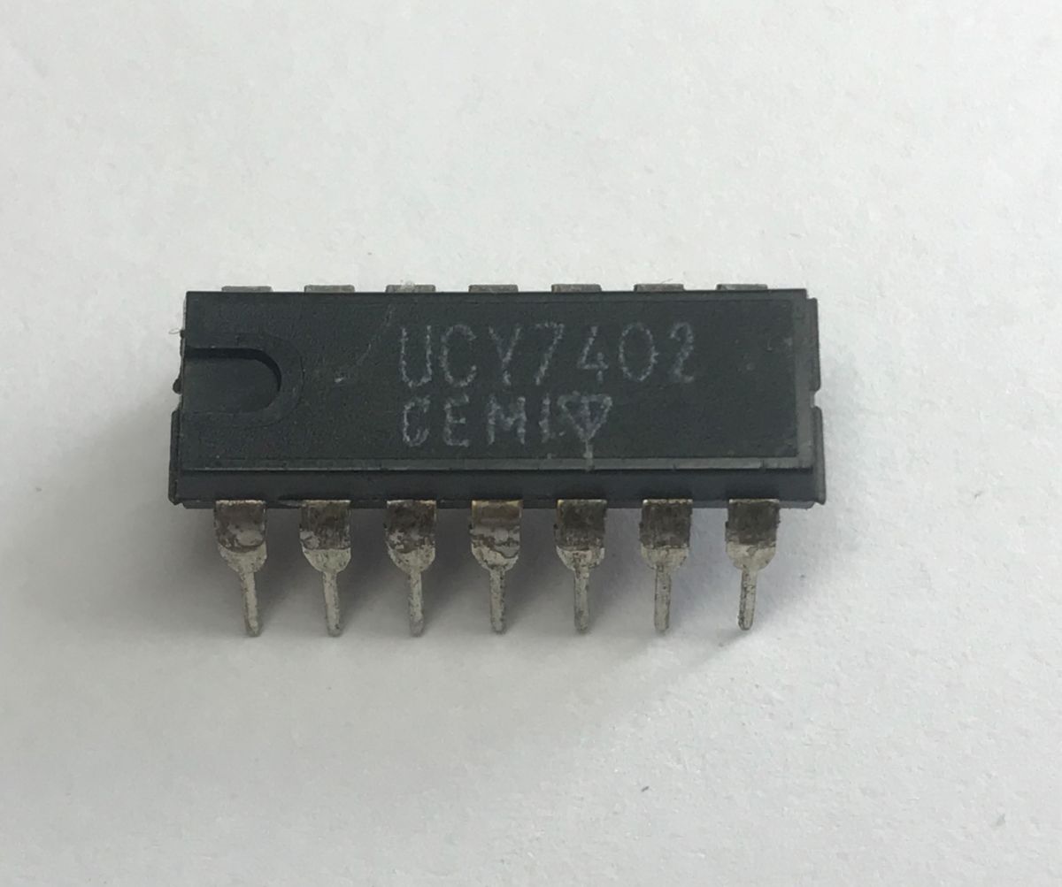
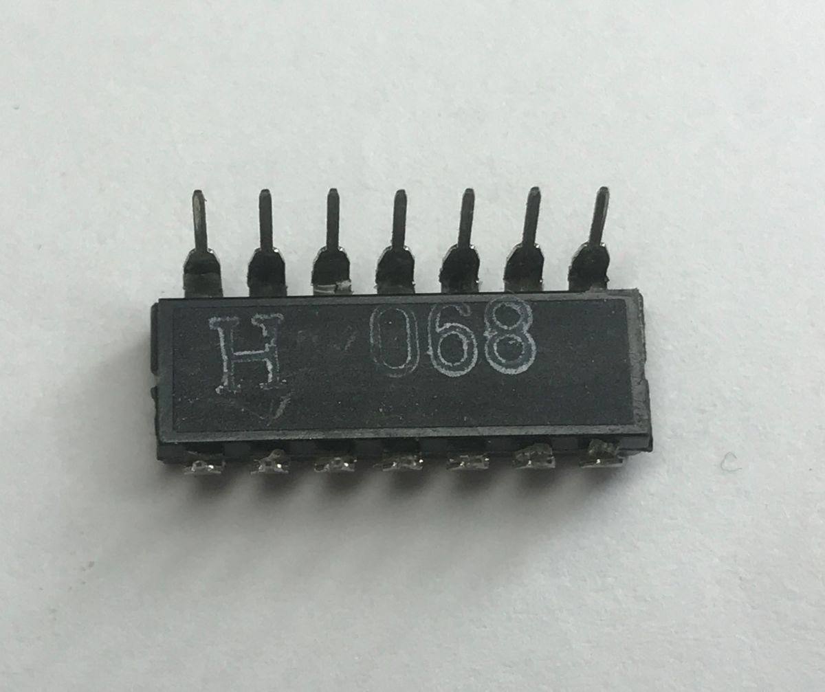
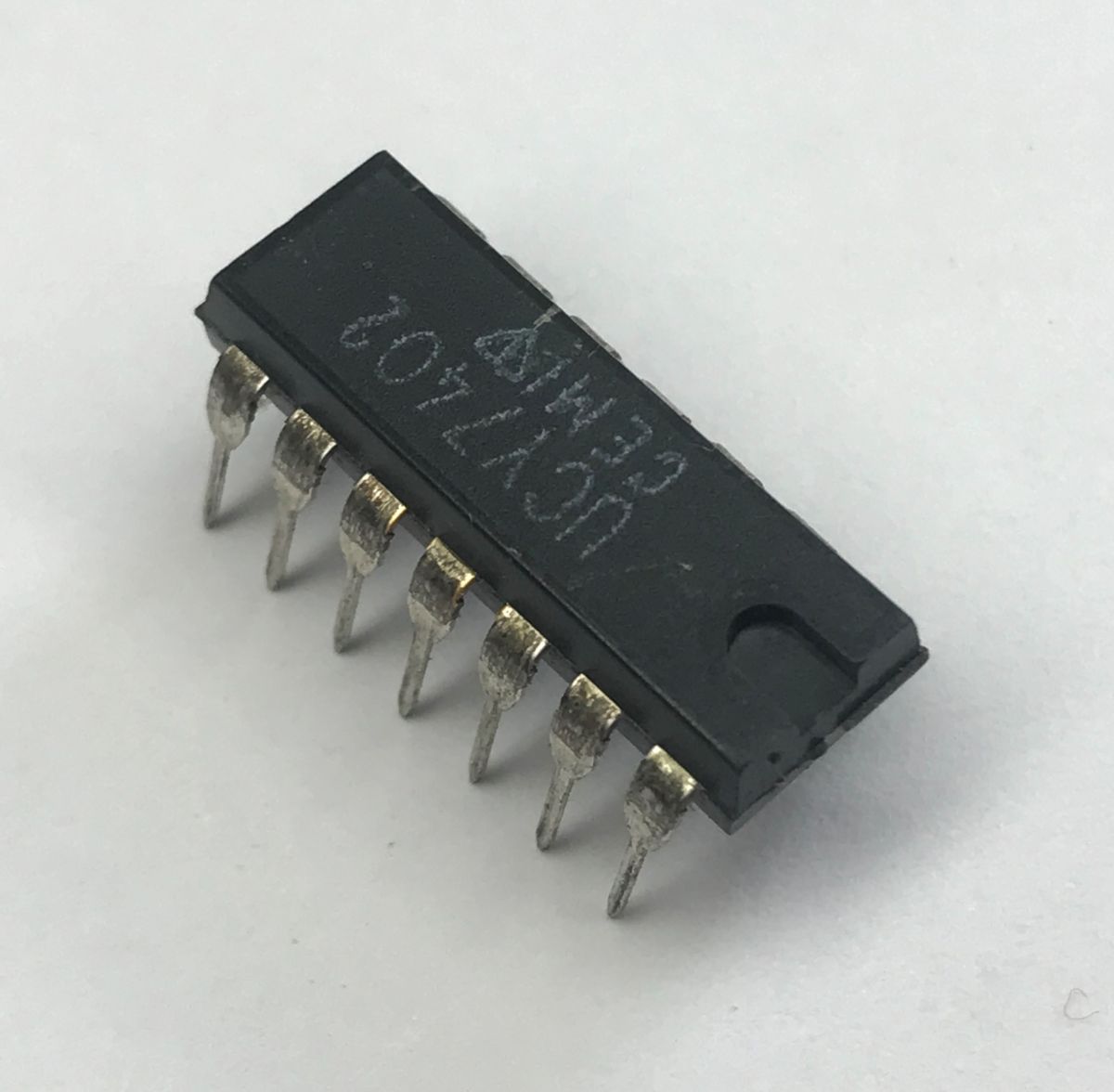
The function can be expressed by the formula:
$$Y = \overline{A + B}$$
The truth table shows that the function returns a high state only when all inputs are in a low state:
| A | B | Y |
| 1 | X | 0 |
| X | 1 | 0 |
| 0 | 0 | 1 |
UCY7402 pinout:
Video demonstration – unlike the previous video, now you just need to press a single button to light up the LED:
UCY7404 consists of six NOT inverters. They perform the logical NOT function.
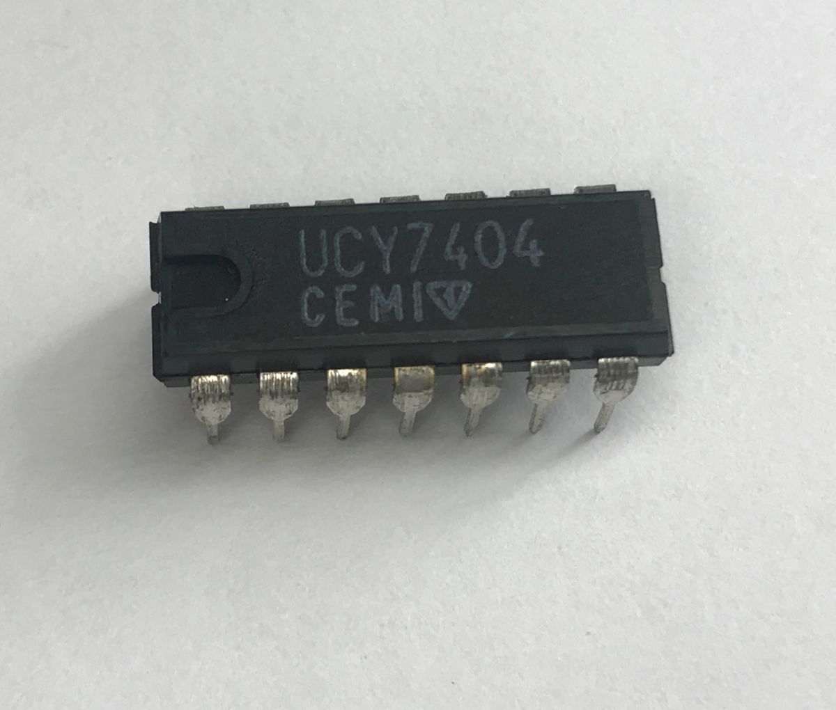
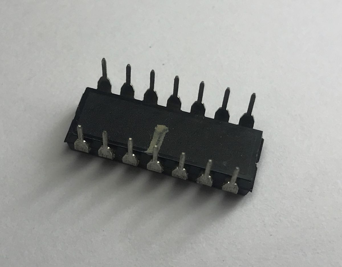
The function can be expressed by the formula:
$$Y = \overline{A}$$
The truth table shows that the function returns a high state only when the input is low:
| A | Y |
| 0 | 1 |
| 1 | 0 |
UCY7404 pinout:
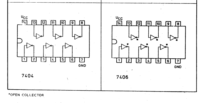
The video presentation of the 7404 hardly needs any commentary:
UCY7406 is also a six-channel NOT inverter, but in this case with open-collector outputs.
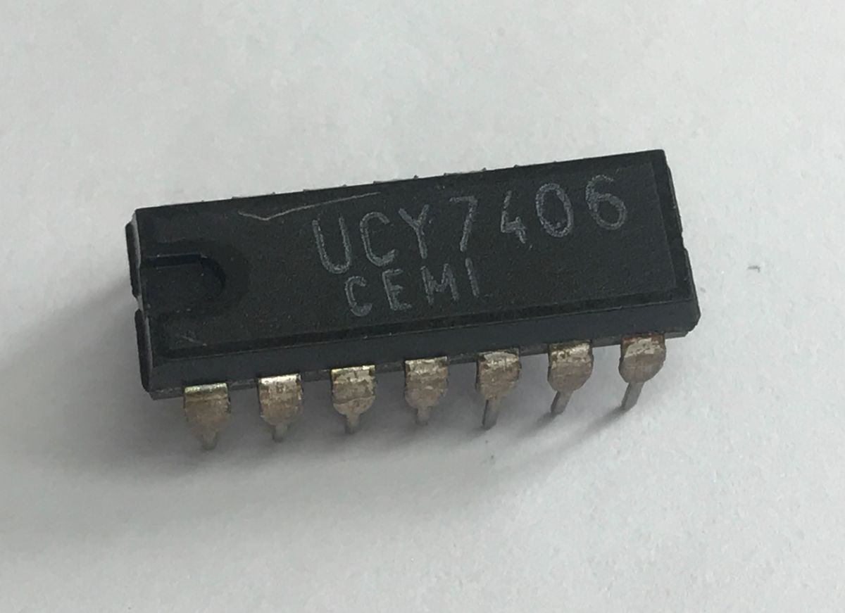
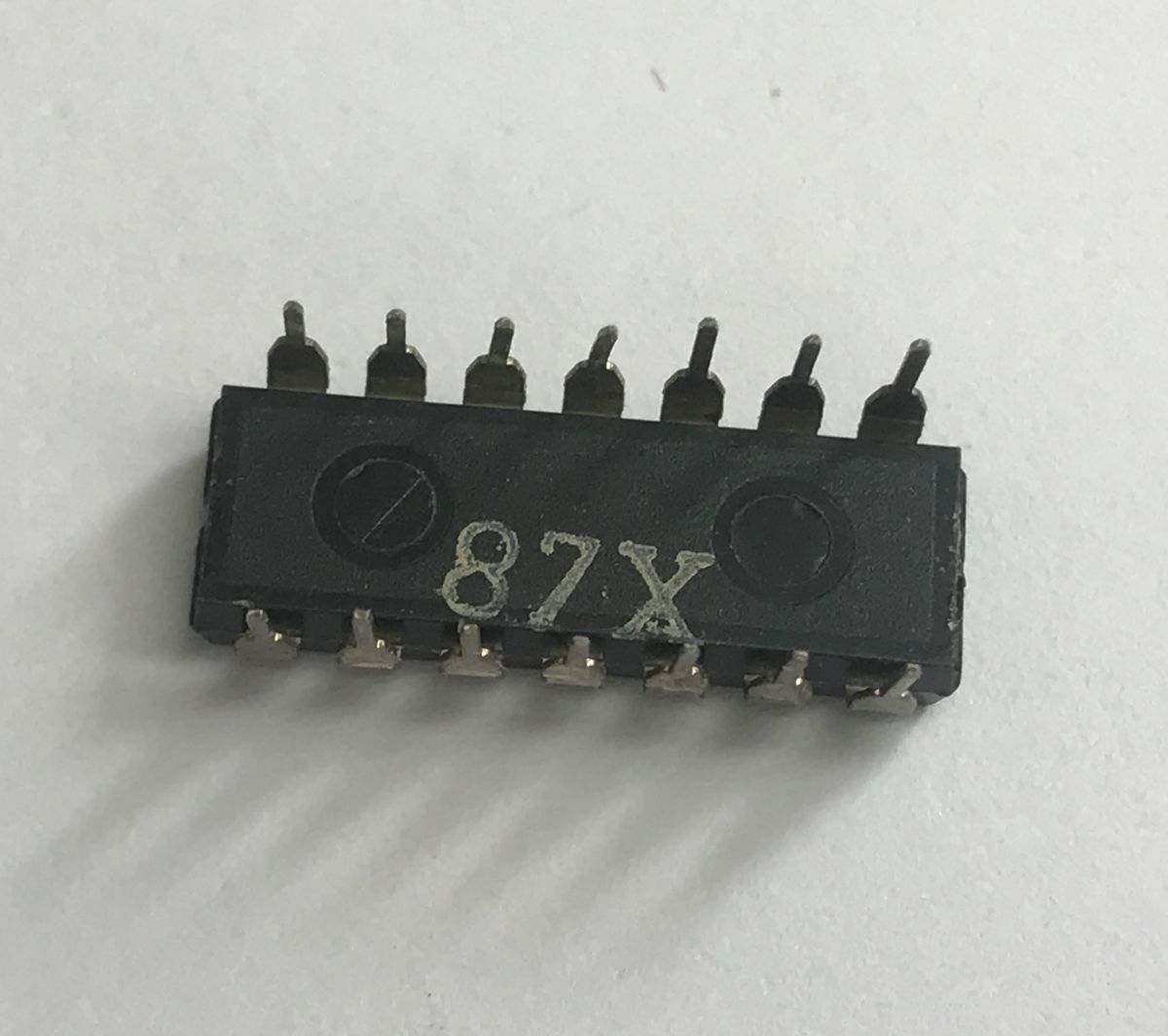
This also allows for the control of loads powered by higher voltages (in the case of the 7406, up to 30V, which facilitates, for example, the control of relays) and for the direct connection of multiple outputs to one another on a single signal line.
UCY7407 These are six non-inverting open-collector buffers. They perform the function of a logic buffer.
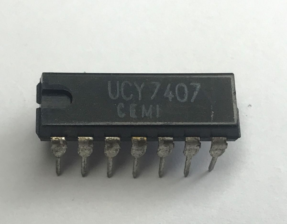
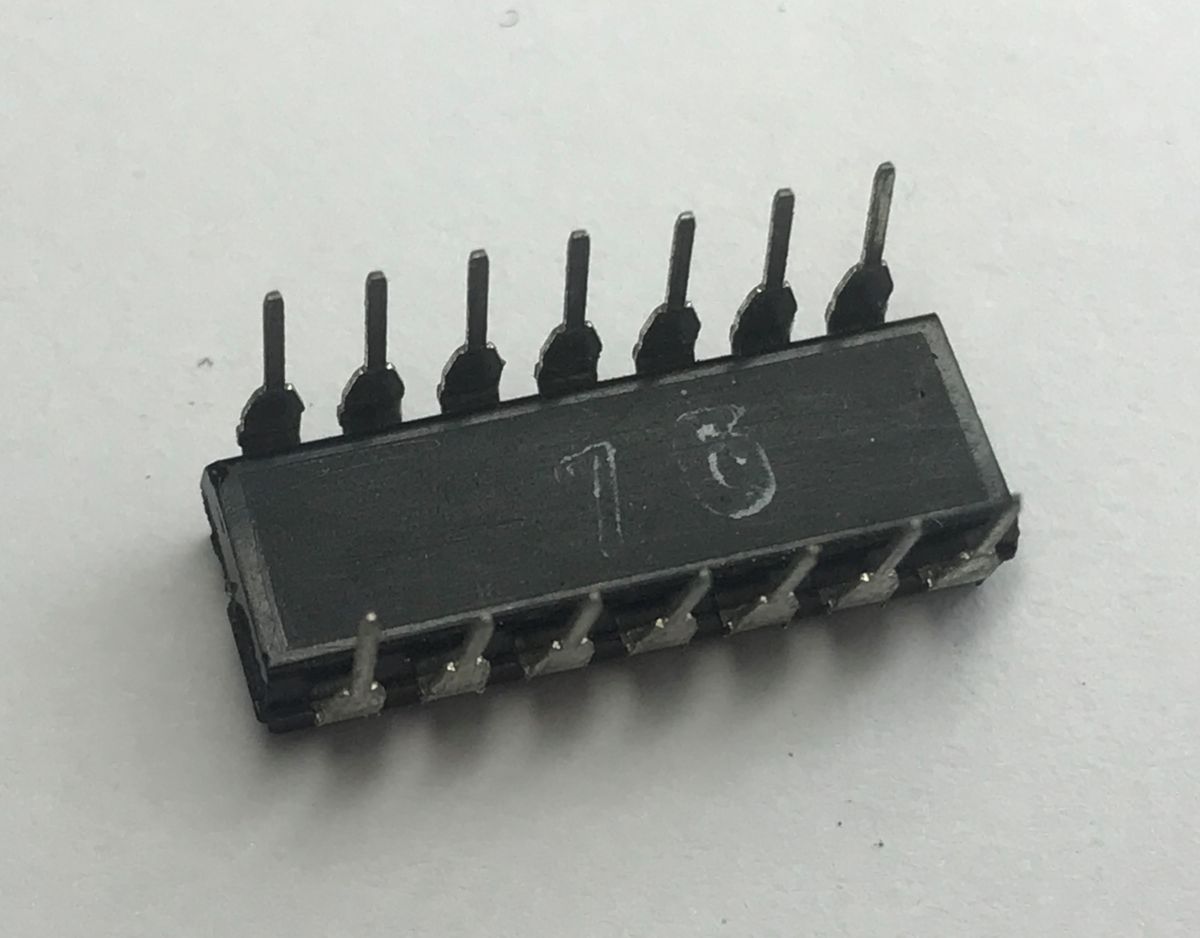
The function can be expressed by the formula:
$$Y = A$$
The truth table shows that the function returns a high level only when the input is high:
| A | Y |
| 0 | 0 |
| 1 | 1 |
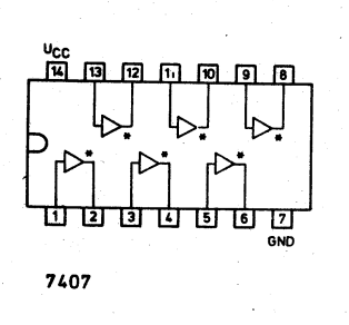
UCY7407 pinout:
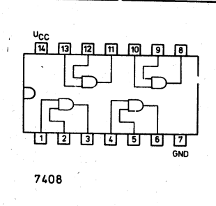
UCY7408 These are four two-input AND gates. They implement the logical product (AND).
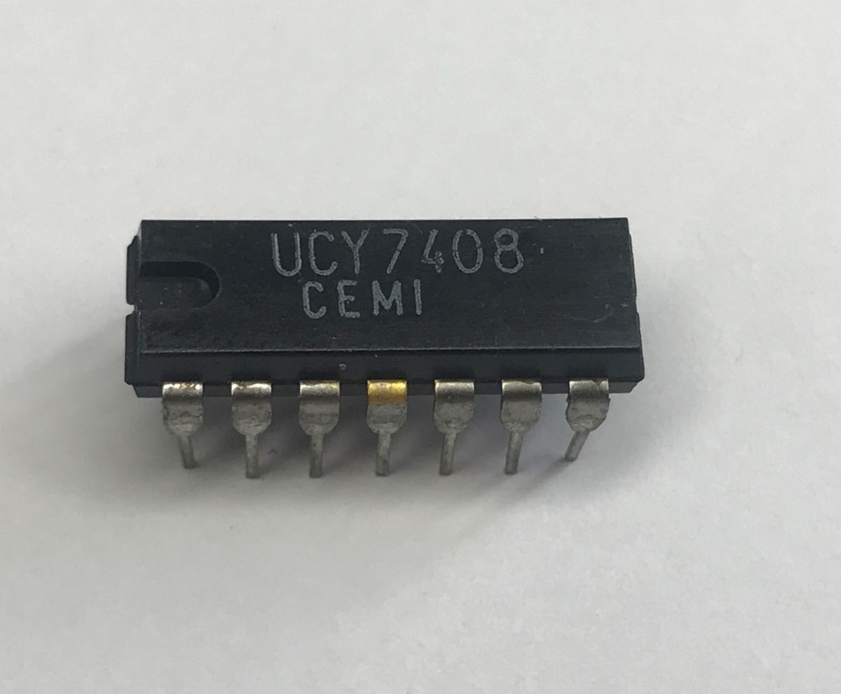
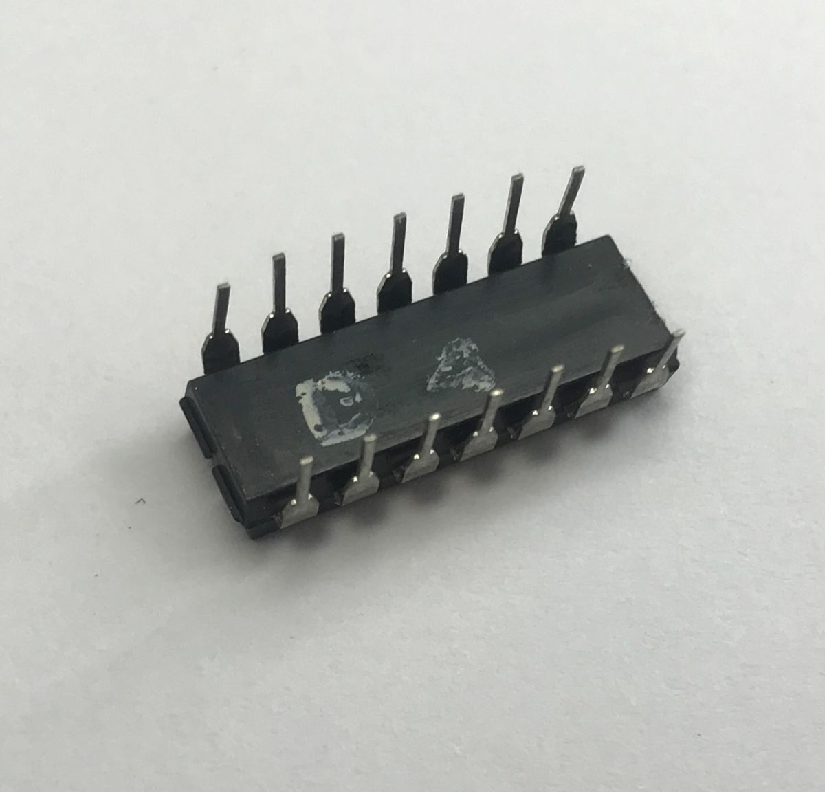
The function can be expressed by the formula:
$$Y = A \cdot B$$
The truth table shows that the function returns a high level only when all inputs are high:
| A | B | Y |
| 1 | 1 | 1 |
| 0 | X | 0 |
| X | 0 | 0 |
UCY7408 pin-out:
As the operation of this circuit is straightforward, I shall omit the presentation.
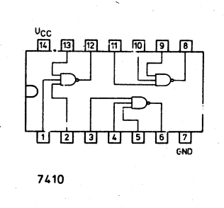
UCY7410 is a circuit containing three three-input NAND gates. These implement the negated logical product (NAND) function.
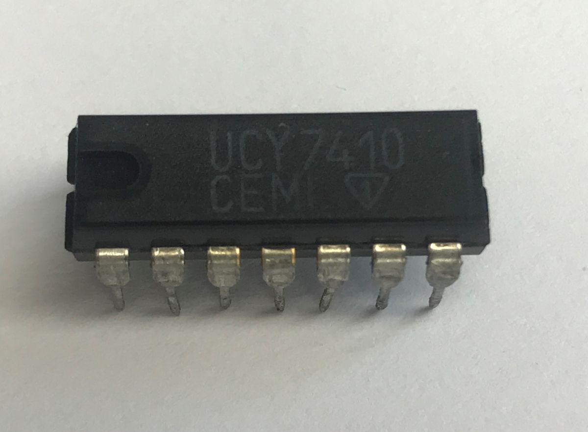
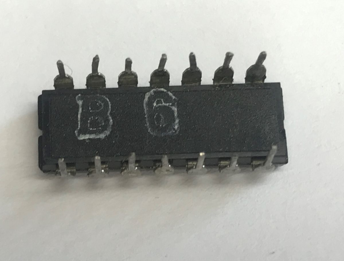
The function can be expressed by the formula:
$$Y = \overline{A \cdot B \cdot C}$$
The truth table shows that the function returns a high state only when at least one of the inputs is in a low state:
| A | B | C | Y |
| 1 | 1 | 1 | 0 |
| 0 | X | X | 1 |
| X | 0 | X | 1 |
| X | X | 0 | 1 |
Derivations:
Video presentation:
UCY7420 are two four-input NAND gates. They implement the logical negated AND (NAND) function.
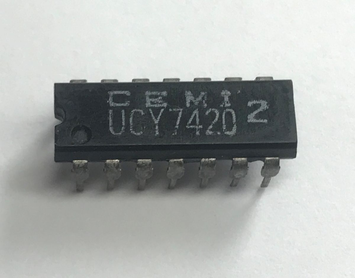
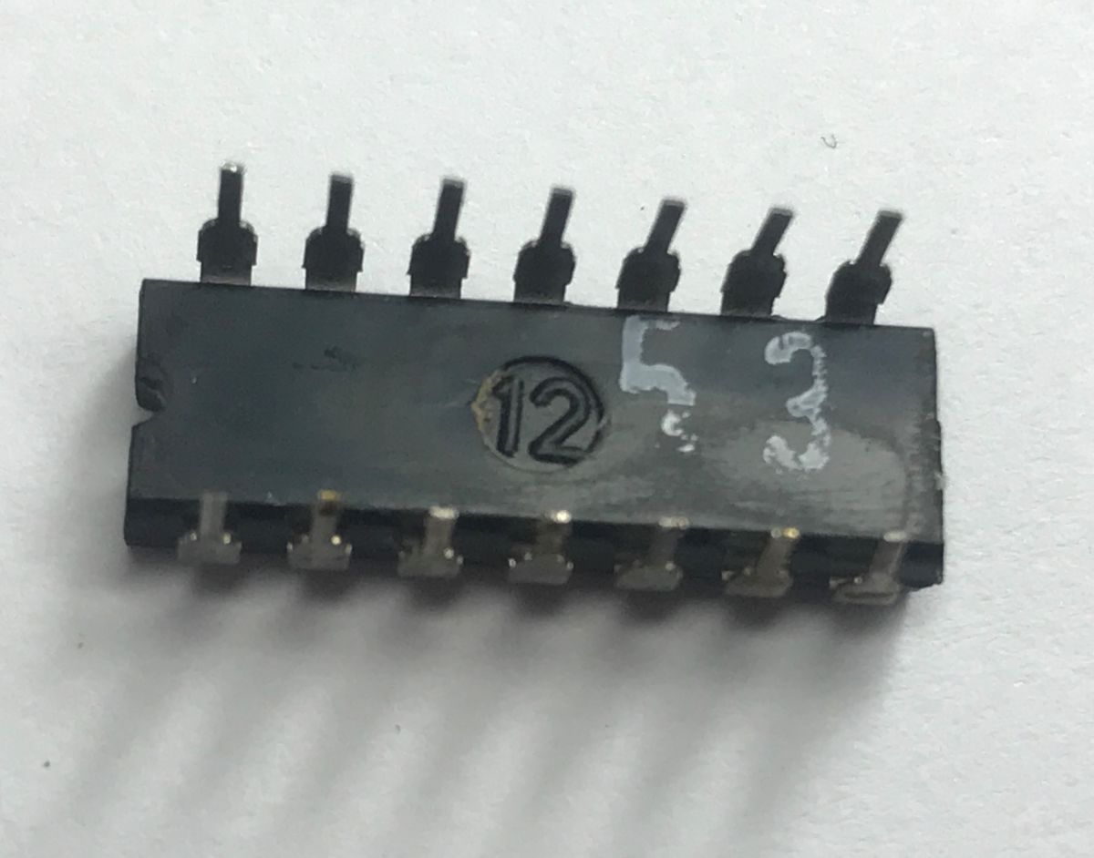
The function can be expressed by the formula:
$$Y = \overline{A \cdot B \cdot C \cdot D}$$
The truth table shows that the function returns a high state only when at least one of the inputs is in a low state:
| A | B | C | D | Y |
| 1 | 1 | 1 | 1 | 0 |
| 0 | X | X | X | 1 |
| X | 0 | X | X | 1 |
| X | X | 0 | X | 1 |
| X | X | X | 0 | 1 |
Video presentation:
This circuit is also available in a buffered version – UCY7440 – with increased output current capacity, allowing it to drive a heavier load.
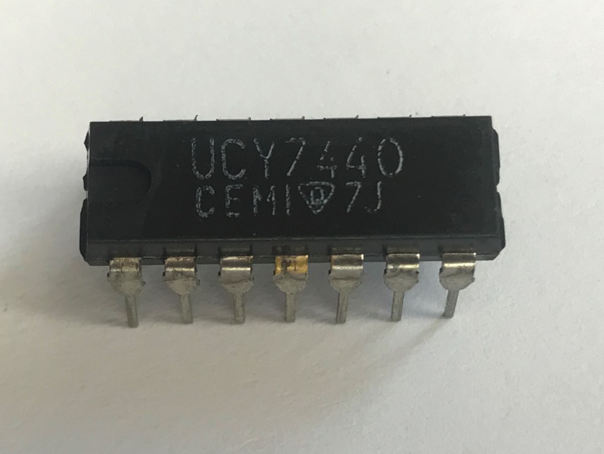
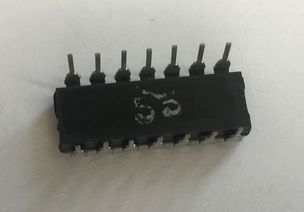
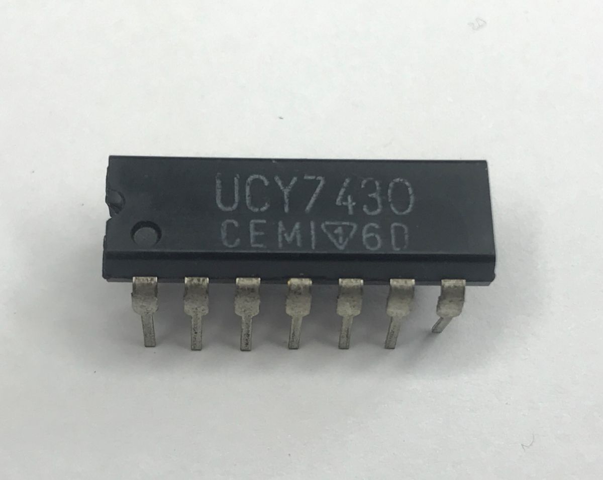
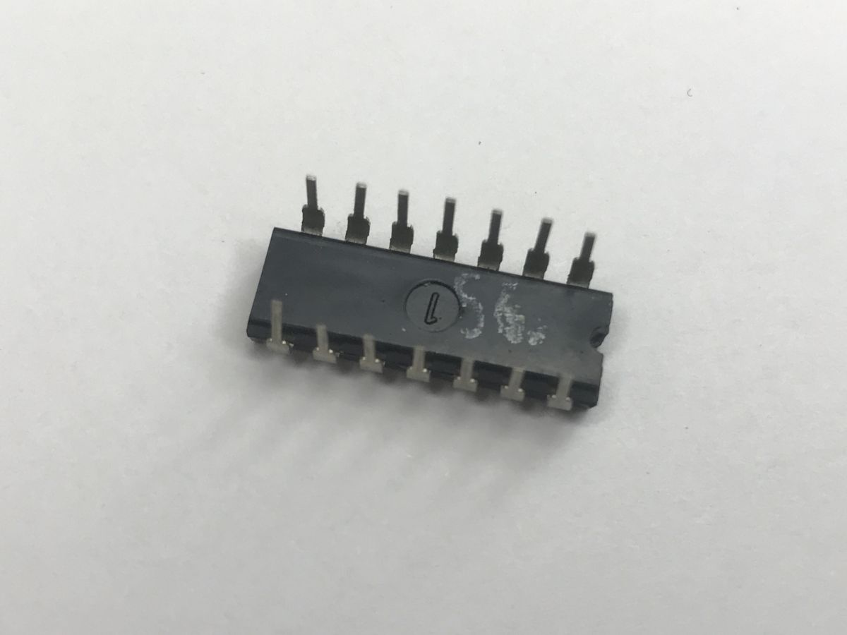
UCY7430 is a circuit comprising a single eight-input NAND gate. It implements the negated AND (NAND) function for as many as eight variables.
The function can be expressed by the formula:
$$Y = \overline{A \cdot B \cdot C \cdot D \cdot E \cdot F \cdot G \cdot H}$$
The truth table shows that the function returns a high state only when at least one of the eight inputs is in a low state:
| A | B | C | D | E | F | G | H | Y |
| 1 | 1 | 1 | 1 | 1 | 1 | 1 | 1 | 0 |
| 0 | X | X | X | X | X | X | X | 1 |
| X | 0 | X | X | X | X | X | X | 1 |
| X | X | 0 | X | X | X | X | X | 1 |
| X | X | X | 0 | X | X | X | X | 1 |
| X | X | X | X | 0 | X | X | X | 1 |
| X | X | X | X | X | 0 | X | X | 1 |
| X | X | X | X | X | X | 0 | X | 1 |
| X | X | X | X | X | X | X | 0 | 1 |
UCY7430 pinout:
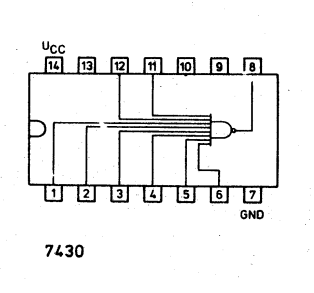
I’ve skipped the video this time; it’s essentially the same as before – you can just picture eight buttons.
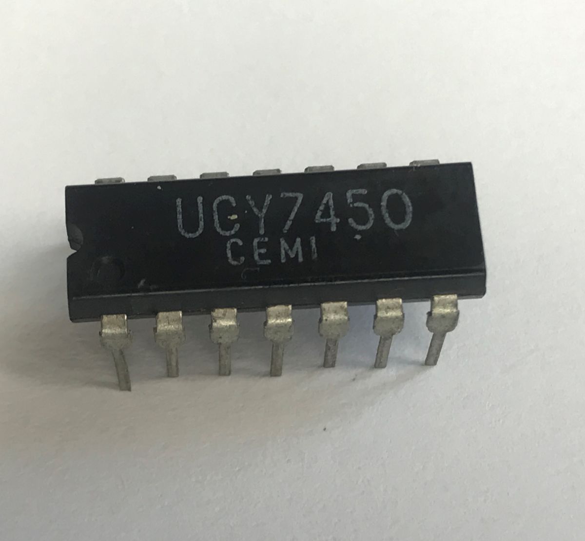
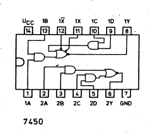
UCY7450 is a chip containing two two-input AND-OR-INVERT (AND-NOR), one of which is expandable. They implement a complex logical function.
The function can be expressed by the formula:
$$Y = \overline{(A \cdot B) + (C \cdot D)}$$
The truth table shows that the function returns a low state only when both inputs of the first or second product are in a high state:
| A | B | C | D | Y |
| 1 | 1 | X | X | 0 |
| X | X | 1 | 1 | 0 |
| 0 | X | 0 | X | 1 |
| 0 | X | X | 0 | 1 |
| X | 0 | 0 | X | 1 |
| X | 0 | X | 0 | 1 |
UCY7450 pinout:
This is clearly shown in the video demonstration – I have to press either the first pair of buttons or the second pair of buttons for the LED to light up:
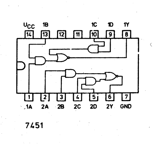
UCY7451 is a chip containing two dual-input AND-OR-INVERT (AND-NOR) gates. It performs the same logical function as the 7450 model, but does not have pins for an expander (this circuit is not expandable).
UCY7451 pins:
Video presentation:
That’s enough for now. Of course, these weren’t all the circuits in this series, as the range produced by CEMI was very extensive. I’ve actually left quite a lot out, as I’ve focused here exclusively on the simplest logic gates – I intend to cover more complex sequential and combinational circuits in a separate post. Take the UCY7475, for example – it’s already waiting in my drawer to be connected.
What else is in store for a presentation? Too many to list and write down – a wide variety of circuits, but including, amongst others, the UCY7475, UCY7472, UCY74150, UCY75107, UCY74164, 7U4154PC, MC146818P, MH74141, MH7490A, UCA6473 and ULY7710.
To sum up, the old UCY series chips, despite the passage of several decades, are still fully functional and fascinating components. Their simple, purely hardware-based nature makes them excellent material for learning the basics of digital technology. I’d encourage everyone to dig these classics out of a drawer and have a go experimenting with them on a breadboard.
Have you come across circuits like these, and if so, when, in which devices, and how would you rate their reliability?

p.kaczmarek2 wrote 14739 posts with
rating 12834 , helped 659 times.
Been with us since 2014 year.
Comments
As well as the CEMI chips, I have a few Soviet equivalents of the K155 – a piece of electronic history. I remember the EdW series ‘First Steps in Digital Electronics’ and the picture of a dinosaur representing... [Read more]
You’ve actually given me an idea for a DIY project – perhaps a tester for circuits like this, in some form, e.g. based on a PIC18F4550, might not be such a bad idea. [Read more]
That’s a good idea. I use the TL866II PLUS (XGRPO) programmer; it has a ‘test logic’ function for TTL and CMOS, and you can create your own tests. [Read more]
I don’t think I’ve ever had so many different 74-series TTL chips on my desk at the same time. I wonder in what way the 74 series might have been better than the CMOS CD40 series? Perhaps the versions... [Read more]
This is, of course, thanks to the reader who gave them to me. Do you have any ideas what else I could make with them? I also need to have a proper stock-take, but for now the number of parcels I’m receiving... [Read more]
This generator can have quite a low THD, and it’s worth having a look inside it 😀 [Read more]
There was also the UCY74Axx series (not UCA74xx), presumably manufactured under a Soviet licence. They were a bit slower but had slightly higher power consumption. [Read more]
:smile: In 1983 a series began at Radioelektronik a series began Fundamentals of Digital Technology :idea: https://obrazki.elektroda.pl/1138589500_1784976141_bigthumb.jpg This is... [Read more]
Generally speaking, the 4000 series (40), manufactured using CMOS technology, is considerably slower than even the old 74 series. However, the 4000 series can operate at voltages ranging from approximately... [Read more]
Interesting material, @acek1. By the way, when I was working on this topic, I based my work on the documentation for the “UCY 74 / UCA 64", and one thing surprised me there – that although it’s in Polish... [Read more]