





Internal components, repairs and firmware emulation – Manta DVBT018 DVB-T2 tuner
TL;DR 
- A dead Manta DVBT018 DVB-T2/HEVC tuner becomes a Low-ESR capacitor repair and firmware-emulation project with an interactive MBoot console.
- A swollen converter-output capacitor caused the failure; an SPI Flash dump, binwalk, Ghidra, Capstone, and Unicorn exposed MStar K5AP firmware running eCos rather than Linux.
- The bootloader loads and LZMA-decompresses a 6,328,740-byte application image, while the eCos boot log reports a 754000000 Hz CPU clock.
- UART register emulation, SPI Flash reads, and timer updates produce a valid U-Boot 2011.06 boot log and a working k5ap# console with environment editing.
- Emulation stalls during eCos driver initialization because the application uses MIPS16e instructions and Unicorn cannot reliably handle the ISA-mode transition.
AI summary based on the discussion. May contain errors.
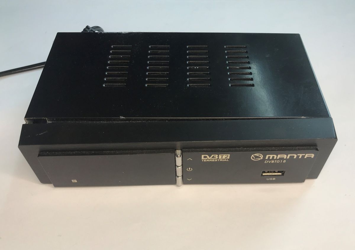
This time, I’m presenting the budget DVB-T/DVB-T2 tuner, the Manta DVBT018, which came to me for repair showing no signs of life. The repair turned into a bit of fun with emulation – I even managed to emulate the operating system’s console (command line)! But let’s start from the beginning. Although very cheap – costing just a few dozen zlotys – the device is fully compatible with second-generation digital terrestrial television (DVB-T2 in HEVC format) and allows you to set up your own channel list. You’d think that at such a low price it wouldn’t be worth repairing, but perhaps it is? Let’s find out!
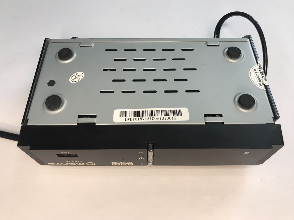
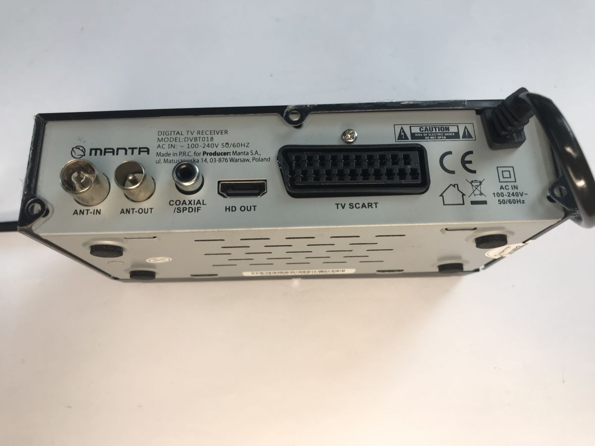
Interior overview
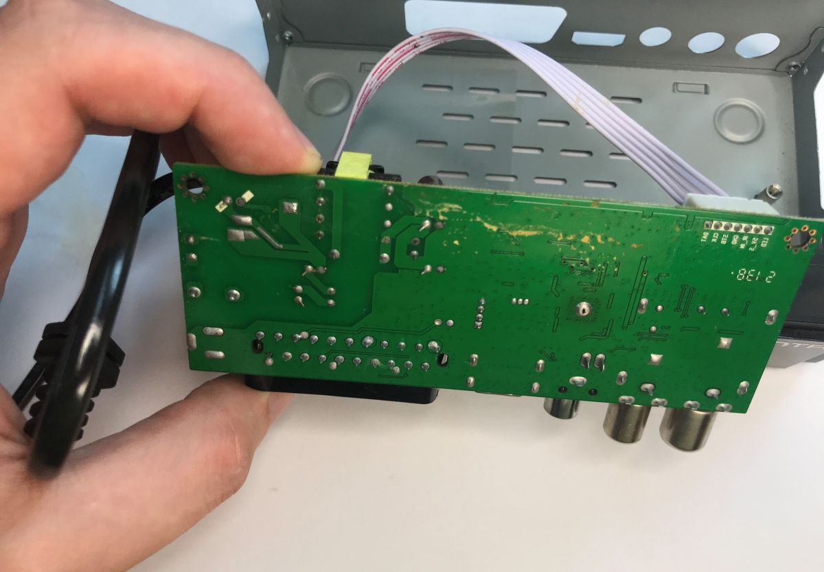
We break the seal and take a look inside. The culprit becomes apparent almost immediately – it’s that suspiciously tall capacitor. First, however, we’ll remove the circuit board – there are no components on the underside, but we need to get to the solder joints.
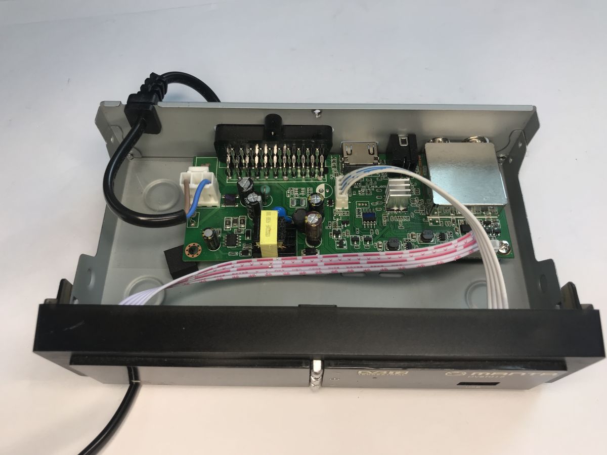
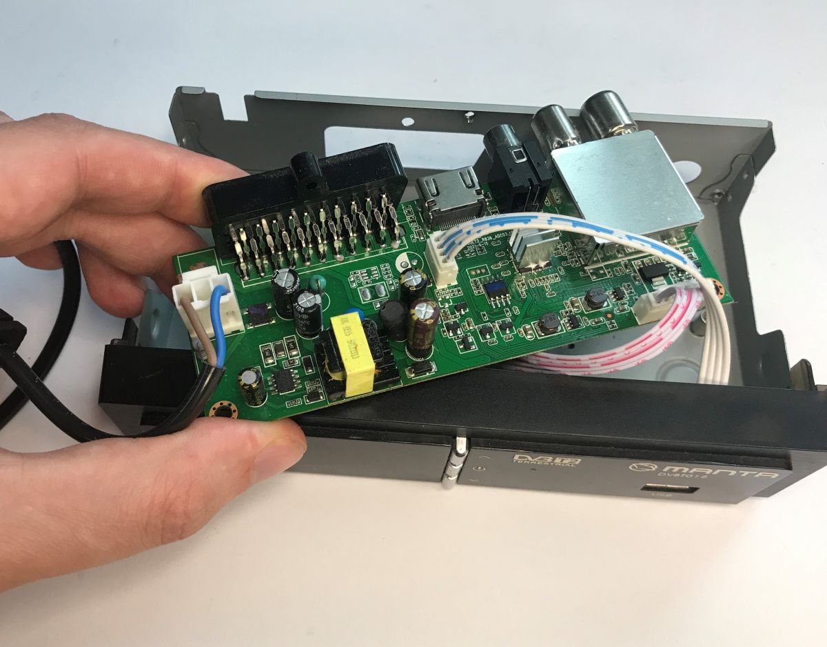
On the circuit board, I’d highlight three sections – a flyback-topology switching power supply, the main microcontroller with Flash memory, and the RF tuner:
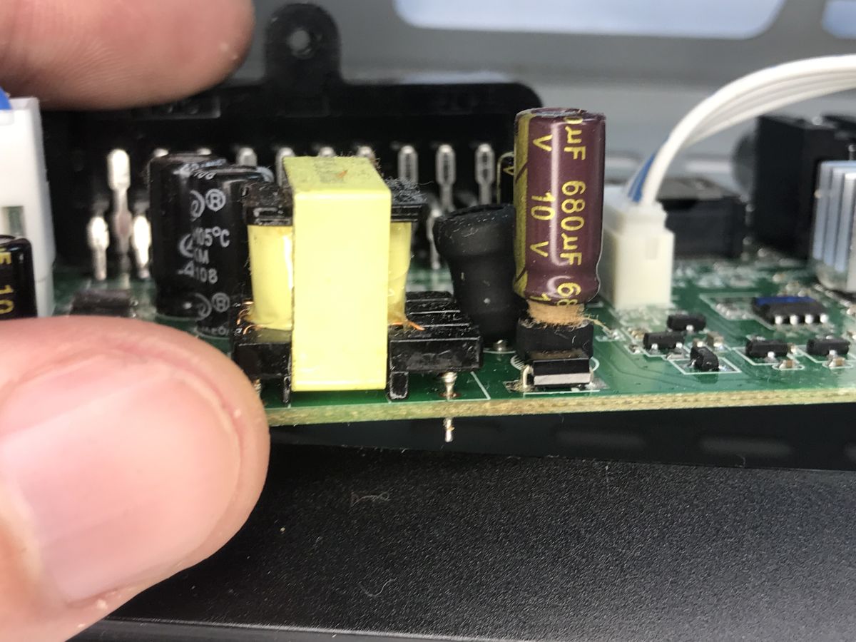
And there’s the culprit:
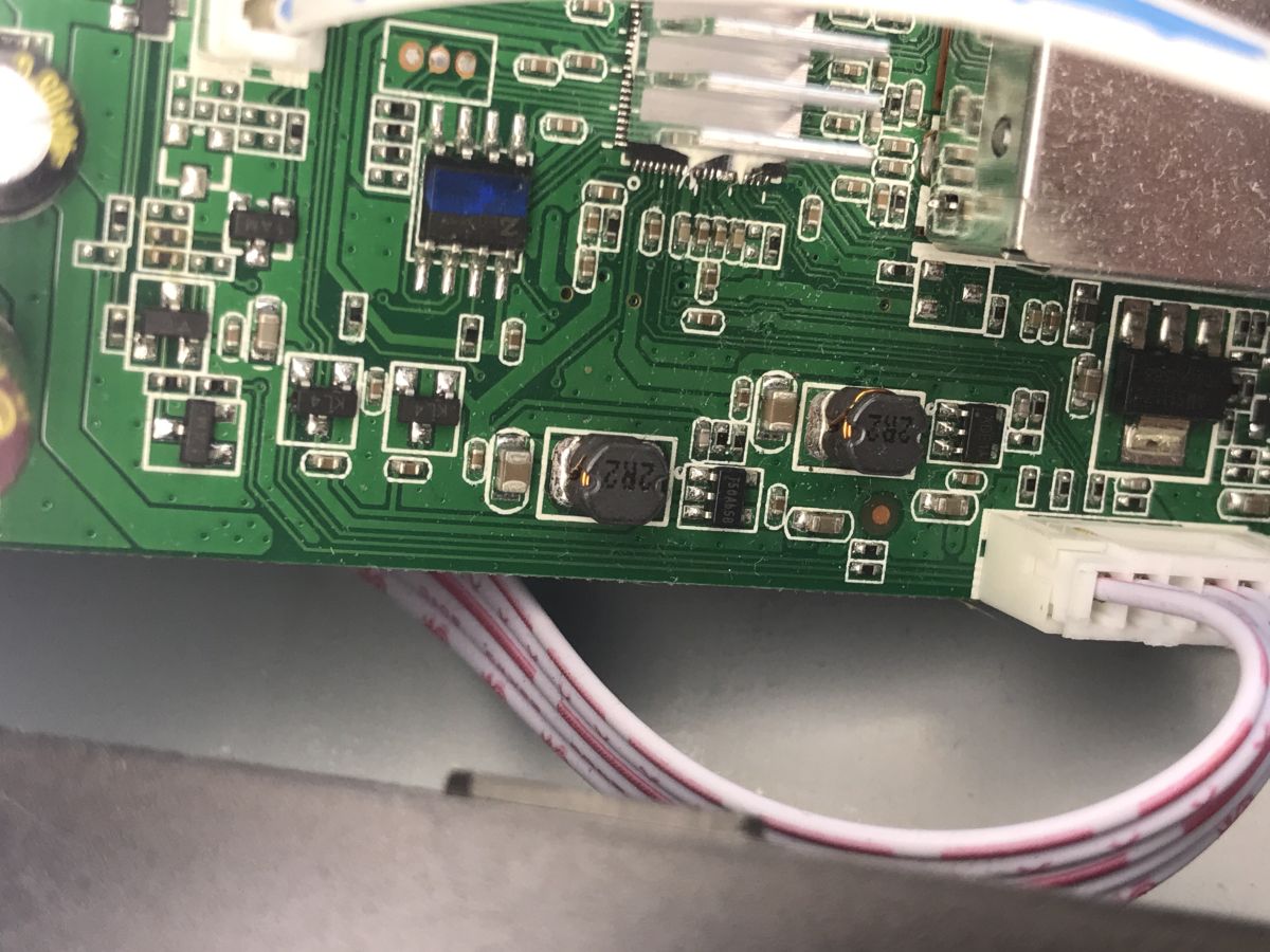
Incidentally, these days, at such low power levels, converters don’t even use optocouplers. This is known as PSR – Primary Side Regulation. This little LY2318 chip even contains a switching transistor.
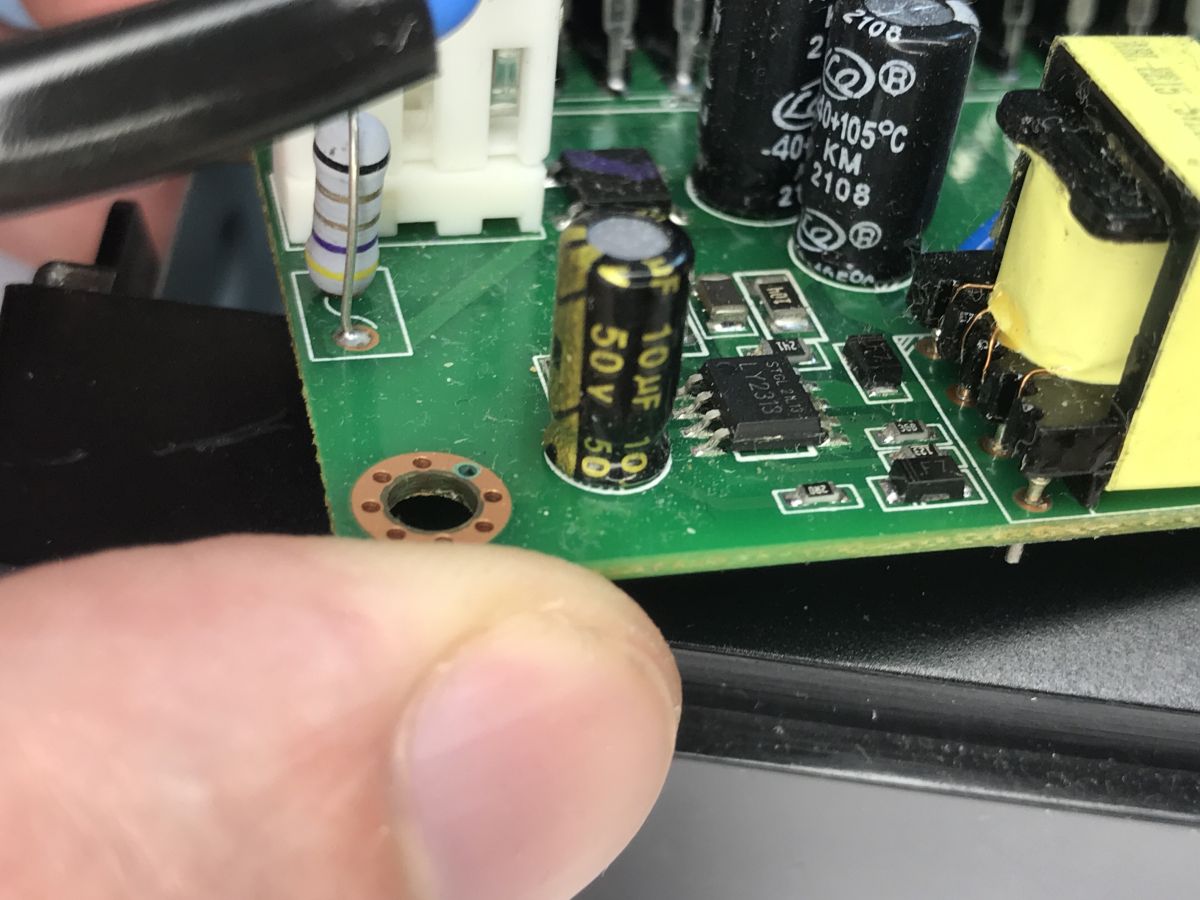
It doesn’t power the MCU directly; it generates 5 V, and then there are further step-down converters, probably down to 3.3 V or lower.
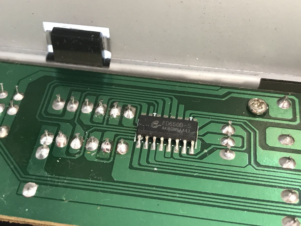
The display is controlled by the FD650, which I have discussed previously .
The RF stage is based on the Rafael Micro R836.
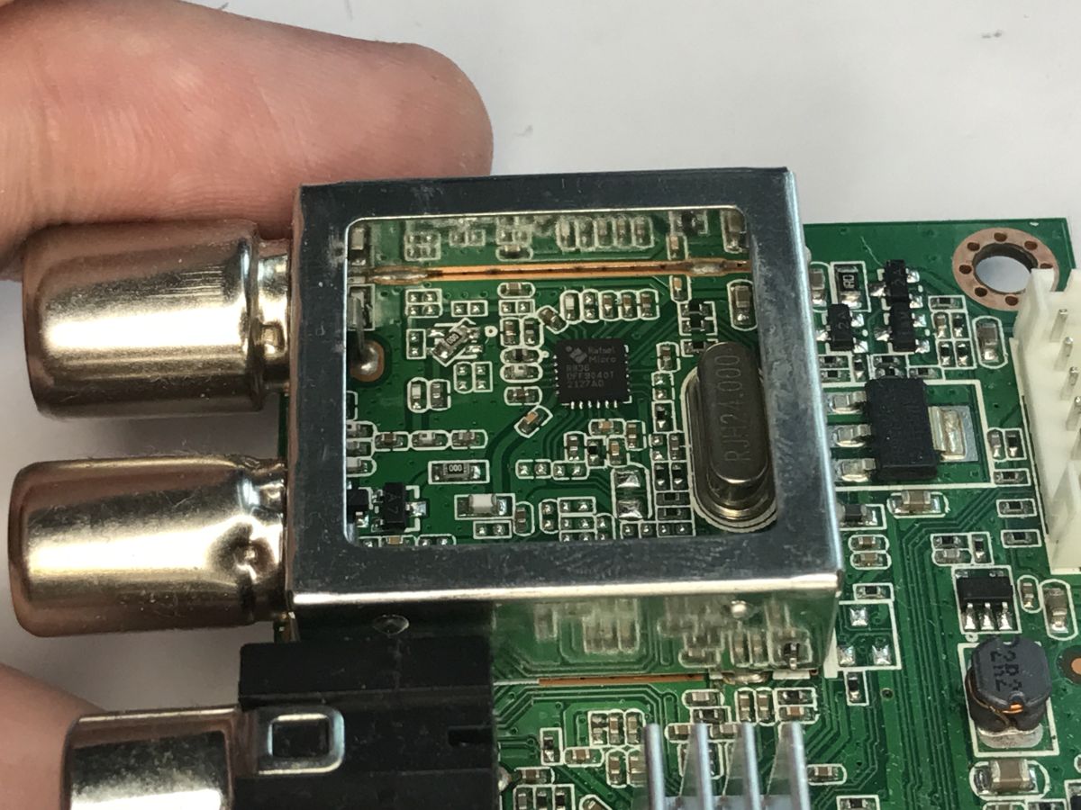
There is some information about it online:
https://github.com/siddolo/R836-reverse-engineering
Repair
Now for the repair itself – you simply need to desolder the capacitor; I use flux to help with this. Next, you’ll need a replacement – it can’t be just any capacitor, it must be a Low ESR type. One suitable for the converter’s output. The capacitance should ideally match the original – not lower – and the voltage rating should also not be lower.
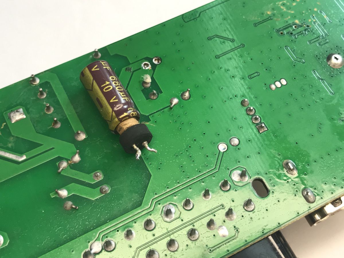
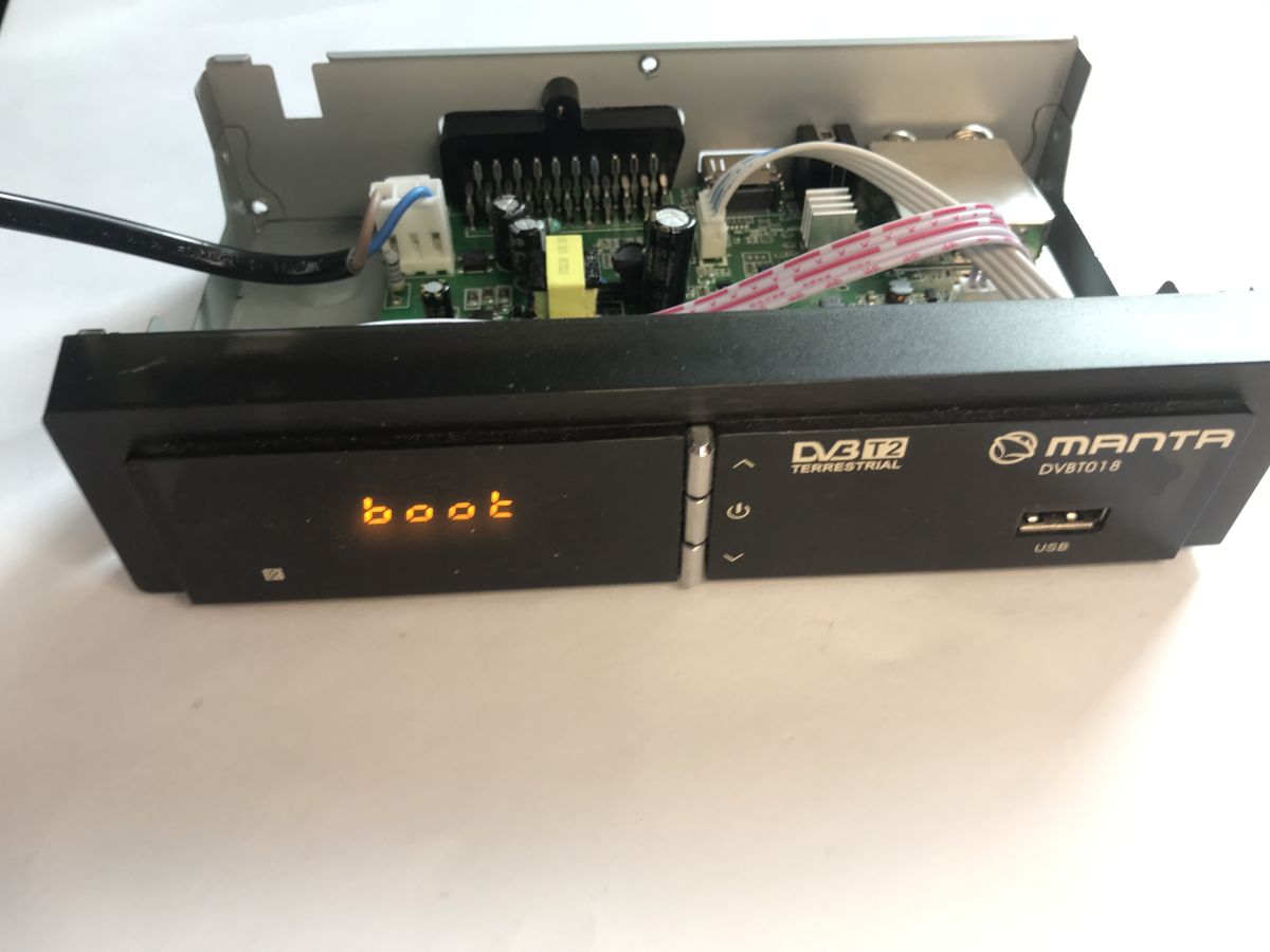
It’s hardly surprising that the tuner works after this repair.
Flash dumping
Now for the most interesting part – the flash memory dump. It has a simple SPI interface. I desolder it using a hot-air gun, then solder it onto a CH341 socket and use that to dump it onto the computer.
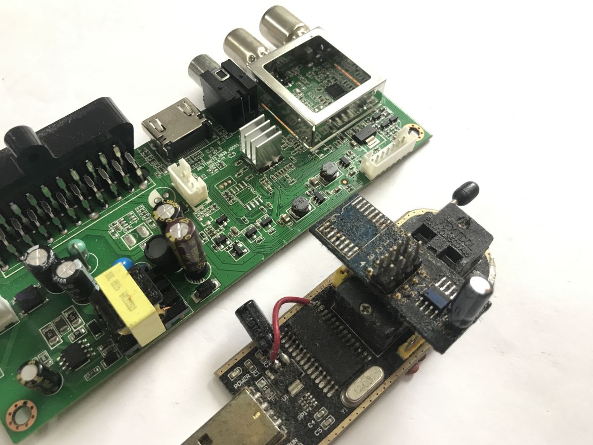
On the PC side, I use NeoProgrammer.
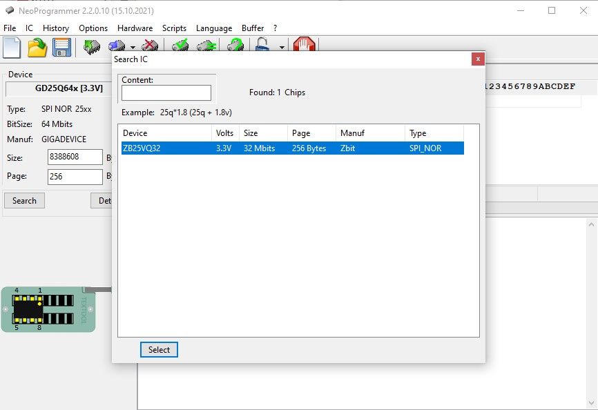
Copy of the batch file:
https://github.com/openshwprojects/FlashDumps/commit/7c15d12800ae4b96f645c9da617f6da586fd9ab9
Firmware analysis
The first step I recommend is to use binwalk, I discussed it two years ago . In this case, binwalk I also ran it via WSL:
Code: Bash
DECIMAL       HEXADECIMAL     DESCRIPTION
--------------------------------------------------------------------------------
23072         0x5A20          SHA256 hash constants, little endian
46336         0xB500          LZMA compressed data, properties: 0x6C, dictionary size: 524288 bytes, uncompressed size: 405280 bytes
184320        0x2D000         JPEG image data, JFIF standard 1.01
204828        0x3201C         LZMA compressed data, properties: 0x6C, dictionary size: 8388608 bytes, uncompressed size: 6328740 bytes
That’s how I discovered the separate sections. Two streams: LZMA and JPEG – that is, the start-up logo.

Subtitles, plain strings:
Code: Bash
MBOT-1106.0.10.936a0fd.201806111716
Board=K5AP_BD_MST297B_D01A
MBoot_IN=SPI_FLASH
Kernel=Unkown
Security=Non-TEE
The K5AP_BD_MST297B_D01A board, i.e. the K5AP platform from MStar. The MST297B itself is likely the designation for the base board design, and the processor is most likely the MStar MSA7T10E, although in the end I didn’t even remove the heat sink, as the tuner had to be returned to the owner quickly after repair (some people need their TV straight away and don’t want to wait any longer). The bootloader is MBoot, based on U-Boot 2011.06. It is non-TEE, so the payload is neither encrypted nor signed.
The environment variables are located at 0x3FE000 (with a copy at 0x3FF000):
bootcmd=usb exit;spi_rdc 0x80B00000 0x3201C 0x2A6BDE; LzmaDec 0x80B00000 0x2A6BDE 0x80000180 0x81000000; go 0x80000224;
bootdelay=0
Here is the complete boot sequence: load 0x2A6BDE bytes from 0x3201C to 0x80B00000, decompress LZMA at 0x80000180, jump to 0x80000224.
This is confirmed by the header at 0x32000, with big-endian fields despite the CPU being little-endian:
DE AD BE EF   magic
00 2A 6B DE   rozmiar spakowany
80 00 01 80   adres ładowania
80 00 02 24   punkt wejścia
00 03 20 1C   offset danych
Unpacking both sections takes just a few lines in Python:
Code: Python
I identified the processor by disassembling the start of the payload (the first 0x20 bytes are the header; the code continues). It’s a little-endian MIPS32 – cache initialisation and writes to the MStar peripheral space (RIU) at 0xBF200000:
0x94000054: lui   $t0, 0xbf00
0x94000068: lui   $t0, 0xbf20
0x94000070: sw    $t1, 0x6700($t0)
0x940000B0: cache 5, ($s0)
0x94000110: lui   $ra, 0x9400      ; skok do 0x94000600
And one more thing – this isn’t Linux. The variable
console=ttyS2,115200n8and the message
Kernel=Unknownare misleading, but the bootloader uses it rather than
bootm, meaning it jumps to a raw binary image. The unpacked application does not contain the string “Linux version”; instead, it contains eCos, MsOS and Utopia – the eCos real-time system with the MStar Utopia layer.
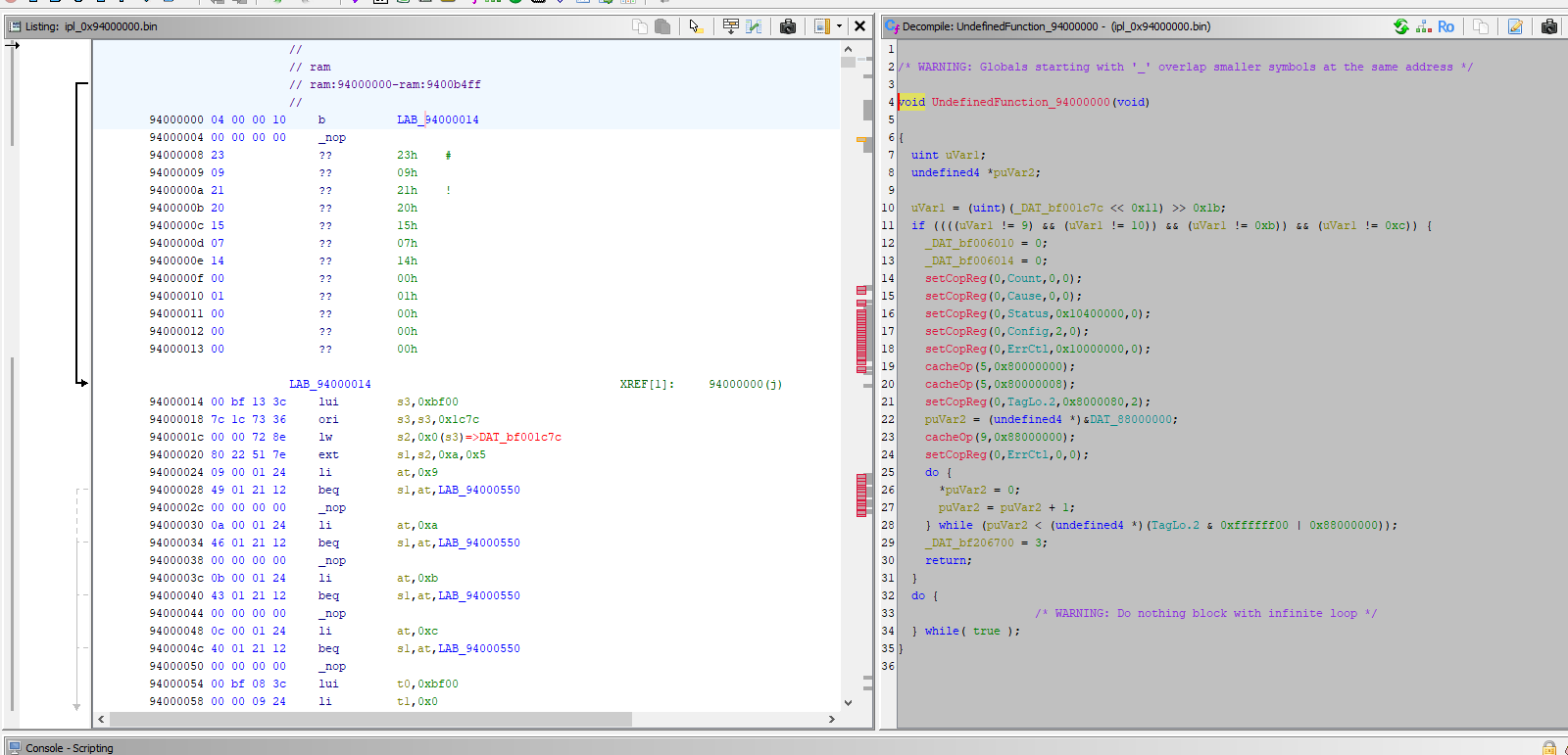
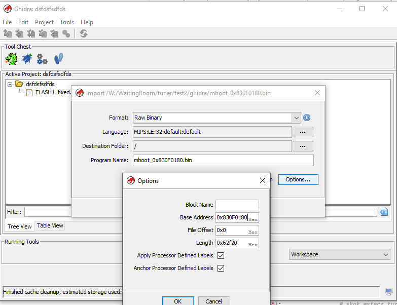
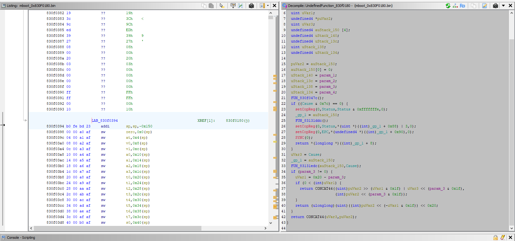
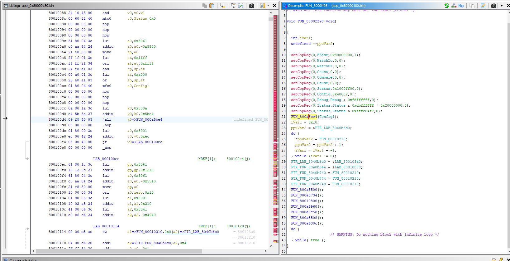
For anyone who wants to tinker with Ghidra, I’m uploading some ready-made images – they need to be loaded as Raw Binary, MIPS:LE:32:default, with the following base addresses:
ipl_0x94000000.bin 46336 B base 0x94000000 start code
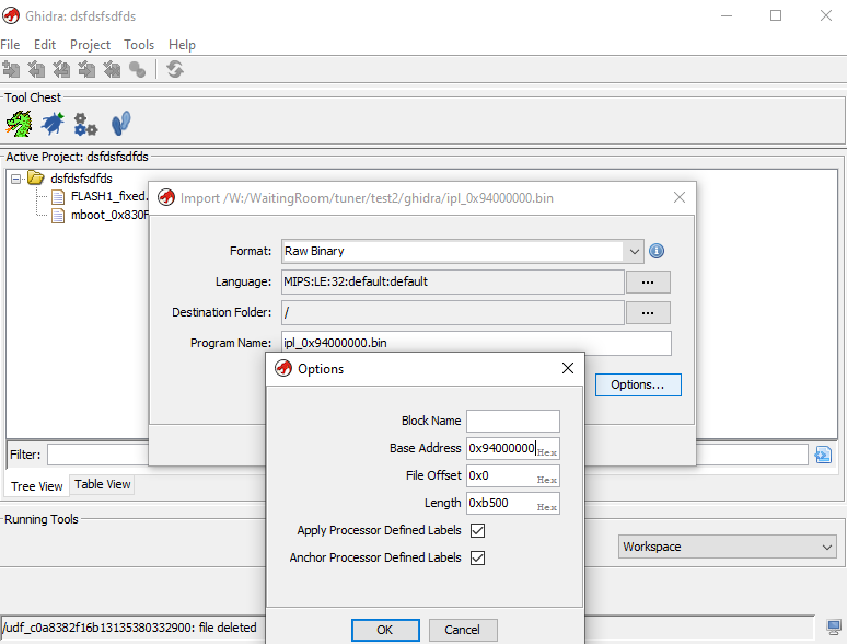
mboot_0x830F0180.bin 405280 B base 0x830F0180 MBoot / U-Boot:
app_0x80000180.bin 6,328,740 B base 0x80000180 eCos, entry 0x80000224
We now have something to work with, but what will we ultimately do with it?
Firmware emulation
I based the emulation concept on exactly the same idea as in earlier presentations:
Running a simple MIPS emulator in Python for the ALI M3801 firmware (Hello World)
BK7231 emulator: preliminary experiments with the Capstone and Unicorn libraries in Python
i.e. Capstone for disassembly and Unicorn for executing code.
First, you need to find the UART – this isn’t difficult. The constant ‘strings’ are immediately visible after decompilation. Presumably, 94000cec is the print function or something similar:
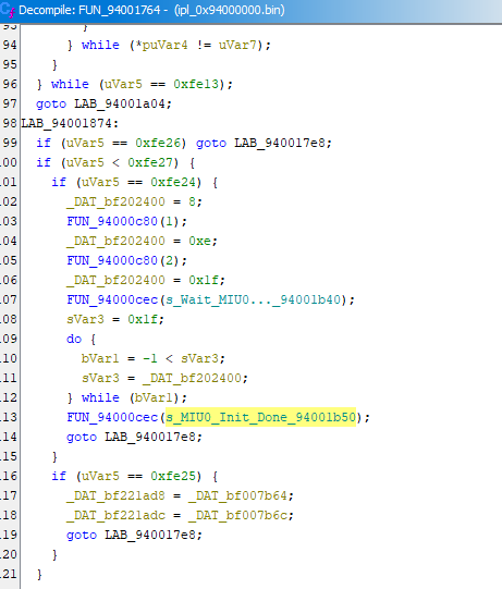
It iterates through the string and calls
putcharfor each character. You can also see that Before the 0x0A (LF) character, it sends 0x0D (CR) – classic line-wrapping for a terminal:
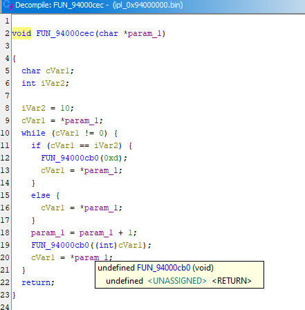
The putchar function itself is a textbook example – two wait loops and a single write operation between them:
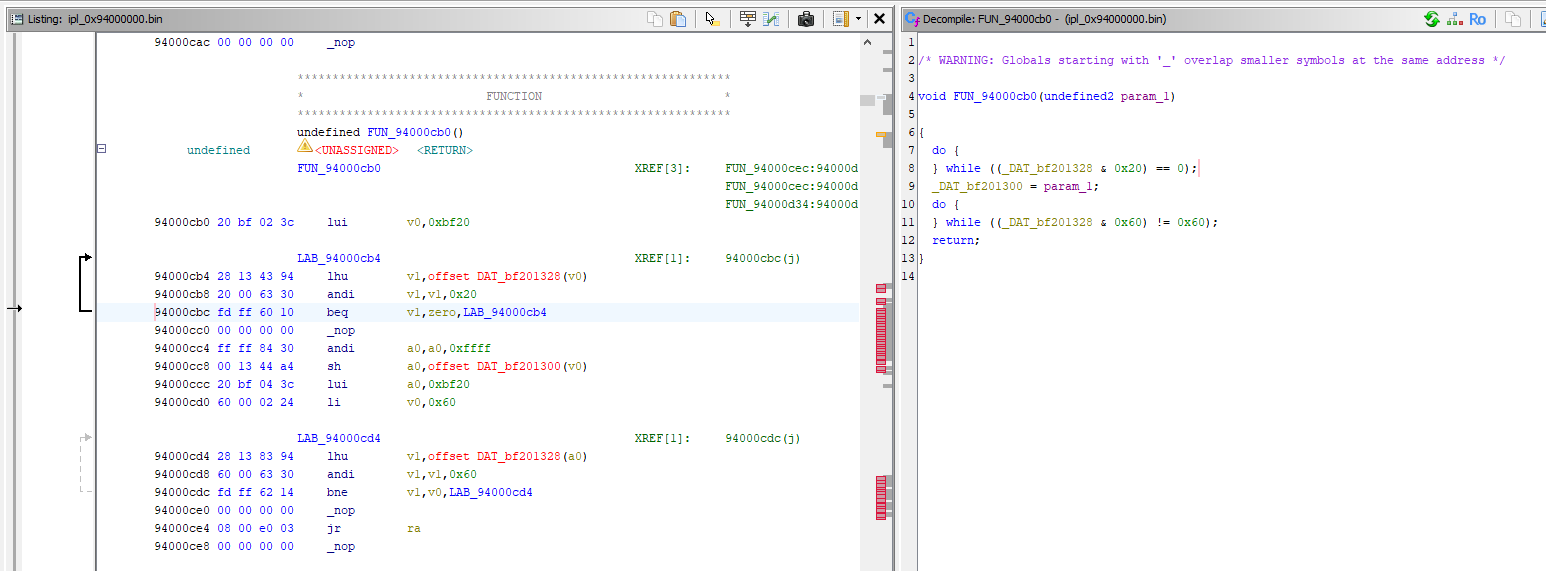
The first loop waits until bit 0x20 is set in register 0xBF201328. Then the character is sent to 0xBF201300. The second loop waits for 0x60, i.e. two bits at once – and that’s a clue as to what sort of chip this is.
This is how the 16550 behaves: bit 0x20 is THRE (‘there is space in the transmit buffer’), bit 0x40 is TEMT (‘transmitter completely empty’), and 0x60 is both together. So the first loop waits for space in the buffer, whilst the second waits until the character physically appears on the line. A blocking, fully flushing putchar – which is why the log is never lost, even when the processor resets the peripherals immediately afterwards. The offsets also match: THR is register 0, LSR is register 5; the registers are spaced 8 bytes apart, hence 0x1300 + 5*8 = 0x1328. Bit 0x01 indicates ‘data available for reading’ – this will be useful later for entering commands.
The address can be verified directly, as the MBoot source code is publicly available – github.com/neuschaefer/mstar-mboot , file sboot/src/amber5/c_riubase.h:
Code: C / C++
RIU addresses using 16-bit words (in the MStar code this is an
unsigned shortpointer), so 0x100980 * 2 = 0x201300, and after adding the RIU base 0xBF000000, the result is exactly 0xBF201300 . I stumbled upon this address through disassembly before I found this header.
So: I substitute a value with bits 0x60 set into the read operation at 0xBF201328, and I output every write to 0xBF201300 to the screen. That’s the whole mechanism for obtaining the log. The ultimate proof that I’ve got it right is empirical – the captured writes yield legible text rather than gibberish.
There’s one catch with memory mapping – Unicorn for MIPS translates KSEG itself, so it maps to physical addresses : 0x94000000 to 0x14000000, and 0xBF200000 to 0x1F200000.
The minimal version that reaches the U-Boot banner is just under 30 lines:
Code: Python
Three things that took me the most time, along with some interesting solutions:
1. An unknown register cannot return a constant. The firmware is full of “wait until the bit sets” loops. If a register keeps returning the same value over and over, the emulation freezes. Alternating between 0xFFFFFFFF and 0 satisfies both “wait for 1” and “wait for 0”.
2. The memory BIST must pass. Register 0x1F2025C0: bit 15 indicates ‘completed’, bits 0x6000 indicate errors. Without this, the IPL outputs BIST0_FAIL and gets stuck in a loop
b .3. Unicorn does not have a CP0 Count register. The read operation “mfc0 rt, $9” results in an exception. It crashes for the first time in the delay routine at 0x94000C80, so the simplest solution is to replace it with an immediate return – and that sorts it out in the code above. If you needed to swap instructions on the fly, there’s a pitfall: mem_write alone isn’t enough , because Unicorn keeps the translated blocks in the cache and continues to execute the old code. A call to
ctl_flush_tb()is necessary; otherwise, the replacement silently does nothing.
The full version also adds support for reads from SPI Flash (otherwise U-Boot won’t find the application image), incrementing the timer variable (without interrupts,
get_timer()never runs and
udelay()loops indefinitely) and the console – more on that in a moment.
Presentation – boot log
We run:
Code: Bash
And we get the log – it’s a shame there wasn’t time to capture it from the original, but I was repairing some hardware for someone.
B
BOOTSPI
BIST0_OK
_OK!decomp
_done
done
[AT][MB][start ub][0]

U-Boot 2011.06 (Sep 23 2021 - 14:07:21)  MBOT-1106.0.10.936a0fd.201806111716


DRAM:
Hello U-Boot
Stack Pointer at: 83627740
mem initial, start 0x82CEE180, len 0x402000
SPI:  uboot held at [8F000000~90000000]
Now running in RAM - U-Boot at: 830F0180
In:    serial
Out:   serial
Err:   serial
[ERROR] do_spi_init_partition:1221: This function doesn't support
============= set bootargs ===============
Unknown command 'panel_pre_init' - try 'help'
[ERROR] raw_read:551: len is zero
[ERROR] LogoInMboot2Dram:146: LogoInMboot2Dram Fail!!
[ERROR] MsDrv_JpdStartDecode:577: MsDrv_JpdStartDecode: Init failed
[ERROR] MsDrv_SetStatus:401: MsDrv_SetStatus:E_JPEG_DECODE_ERR
spi_rdc 0x80B00000 0xB000 0x400
offset 0xB000, size 0x400
spi_rdc 0x80B00000 0x32000 0x400
offset 0x32000, size 0x400
setenv bootcmd ' usb exit;spi_rdc 0x80B00000 0x3201C 0x2A6BDE; LzmaDec 0x80B00000 0x2A6BDE 0x80000180 0x81000000; go 0x80000224;
Saving Environment to SPI Flash...
Write addr=0x003FE000, size=0x00001000
sector erase
Write addr=0x003FF000, size=0x00001000
sector erase

@@@[main_loop][297]@@@
============= set bootargs ===============
Hit any key to stop autoboot:  0
enable dont overwrite function
AC on
Write addr=0x003FE000, size=0x00001000
sector erase
Write addr=0x003FF000, size=0x00001000
sector erase
Check USB port[0]:
[USB] usb_lowlevel_init++
[USB] USB EHCI LIB VER: 2017.08.11-k5ap
[USB] Port 0 is Enabled
[USB] TV_usb_init (UTMI Init) ++
[USB] UTMI Base BF207500
[USB] UHC Base BF204800
[USB] USBC Base BF200E00
[USB] BC Base BF226E00
[USB] init squelch level 0x2
[USB] TV_usb_init--
[USB] Usb_host_Init++
[USB] No USB is connecting
[USB] USB init failed
[USB] usb_lowlevel_init--
Error, couldn't init Lowlevel part
FAIL : can not init usb!!
Write addr=0x003FE000, size=0x00001000
sector erase
Write addr=0x003FF000, size=0x00001000
sector erase
USB is stopped. Please issue 'usb start' first.
offset 0x3201C, size 0x2A6BDE

LZMA Decompression...CRC check success !!
ok
disable interrupts
## Starting application at 0x80000224 ...
B1999 drvEMAC_GetMacAddr
cyg_if_attach.225 - After initialize list 0x804ac364
IFP: 0x804ac354 (eth0)
cyg_if_attach.290 - After inserting 0x8079fa30 into list 0x804ac364
IFP: 0x804ac354 (eth0)
IFA: 0x8079fa30 - <<0x8079faac>>
cyg_if_attach.225 - After initialize list 0x808553c8
IFP: 0x808553b8 (lo0)
cyg_if_attach.290 - After inserting 0x8079f930 into list 0x808553c8
IFP: 0x808553b8 (lo0)
IFA: 0x8079f930 - <<0x8079f9ac>>
Register_netisr [2] fun=0x800bfa79

[eCos][CPU INFO] : CPU Clock = 754000000 : RTC Period = 377000
[MsOS_CPU_DisableInterrupt][3512] MsOS_CPU_DisableInterrupt is not supported
[MsOS_CPU_RestoreInterrupt][3533] MsOS_CPU_RestoreInterrupt is not supported
[MsOS_CPU_DisableInterrupt][3512] MsOS_CPU_DisableInterrupt is not supported
[MsOS_CPU_DisableInterrupt][3512] MsOS_CPU_DisableInterrupt is not supported
[MsOS_CPU_RestoreInterrupt][3533] MsOS_CPU_RestoreInterrupt is not supported
[MsOS_CPU_RestoreInterrupt][3533] MsOS_CPU_RestoreInterrupt is not supported
[MsOS_CPU_DisableInterrupt][3512] MsOS_CPU_DisableInterrupt is not supported
[MsOS_CPU_DisableInterrupt][3512] MsOS_CPU_DisableInterrupt is not supported
[MsOS_CPU_RestoreInterrupt][3533] MsOS_CPU_RestoreInterrupt is not supported
[MsOS_CPU_RestoreInterrupt][3533] MsOS_CPU_RestoreInterrupt is not supported
[eCos] UtopiaInit
shmem name not found.
shmem name not found.
shmem name not found.
   (... "shmem name not found" powtarza się 60 razy ...)
[SYS][ERR][AESDMARegisterToUtopia:2270] Not support AESDMA
<Bad format string: 8029D9F4 : 8039DC2C 803A6324 803A63B4 1C7 80179E27 200000 80161AD1 400000>
<Bad format string: 8029D9F4 : 803A9730 803A96BC 803A9D40 A7E 800A85C4 8060A9DE FF 2>
detect flash type (0xFF, 0x00, 0xFF)
Unknown flash type (0
A few things worth noting from this log:
Now running in RAM – U-Boot at: 830F0180 - this is the same address I previously calculated from the pointers in the command table. Two independent sources agree, so the Ghidra entry is reliable.
LZMA Decompression...CRC check success !! - the bootloader has decompressed the 6 MB image and calculated its checksum. This is the best proof that the basic emulation is accurate: if even a single byte were incorrect, the CRC check would have failed.
## Starting application at 0x80000224 – exactly the entry point from the header at 0x32000.
CPU Clock = 754000000 - processor clocked at 754 MHz. In a tuner costing a few dozen zlotys.
eth0, lo0, Register_netisr - The application loads the network interfaces and the TCP/IP stack, even though this device has no Ethernet port. This is a remnant from larger chips in the same family.
The emulation stops around the time the eCos drivers are initialised. There is a specific reason for this: the application appears to have been compiled for MIPS32 with support for 16-bit instructions (MIPS16e), and Unicorn struggles to handle this mode and switch the ISA. This is evident from the 2-byte-long instructions and the return addresses with bit 0 set (e.g. $ra = 0x8016E9B7, which in MIPS indicates 16-bit instruction mode). None of the available cores in the library I used would work with this...
U-Boot console
Since the emulator has a UART, it works both ways. Bit 0x01 in the LSR indicates ‘data is ready to be read’, so all you need to do is substitute the keystrokes there – and you have an interactive bootloader console.
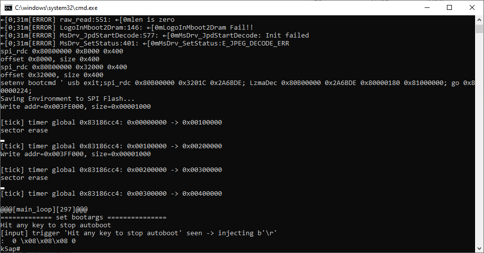
One pitfall: the space bar does not work , even though the bootloader asks for “any key”. MStar has modified this procedure – the character is read and discarded, and only Enter . I checked this by scanning the keys: the space bar, ESC, Ctrl-C and letters are ignored; only CR (0x0D) is recognised.
So, let’s run run_console.bat:
Hit any key to stop autoboot:  0
k5ap# printenv
AP_SW_MODEL=0x0001
AP_SW_VERSION=0x0001
CM_DVBT_ADDR=0x003e8000
CM_DVBT_ORDER=0x003e6000
CM_DVBT_SIZE=0x00015000
CUSTOMER_OUI=0x169B
HW_MODEL=0x0001
HW_VERSION=0x0001
MstarUpgrade_complete=0
UARTOnOff=on
baudrate=115200
bl_dfb_framebuffer_addr=0x01828000
bl_jpd_inter_addr=0x02118800
   (...)
The “k5ap#” prompt indicates a fully functional console – line editing works, Backspace deletes, and the up and down arrows scroll through the command history.
The command help is not registered in this batch, so I extracted the list of commands directly from the cmd_tbl_t array in memory. This yielded 68 commands, including:
printenv setenv saveenv loadenv    spi_rdc spi_wrc spi2usb
bootm go bootcheck read_boot_info    fatload fatls fatwrite usb
mversion showversion checkVersion    ustar austar custar update_mode
A few I tested these straight away in the emulator:
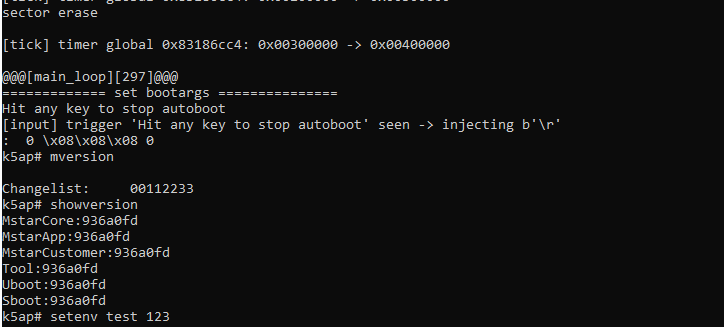
setenvadds entries to the environment variables; these can then be read using
printenv. I set the variable "test" to "123". The result is shown below – it’s too long for a screenshot:
k5ap# printenv
AP_SW_MODEL=0x0001
AP_SW_VERSION=0x0001
CM_DVBT_ADDR=0x003e8000
CM_DVBT_ORDER=0x003e6000
CM_DVBT_SIZE=0x00015000
CUSTOMER_OUI=0x169B
HW_MODEL=0x0001
HW_VERSION=0x0001
MstarUpgrade_complete=0
UARTOnOff=on
baudrate=115200
bl_dfb_framebuffer_addr=0x01828000
bl_jpd_inter_addr=0x02118800
bl_jpd_inter_size=0x00630000
bl_jpd_read_addr=0x01c1c800
bl_jpd_read_size=0x00100000
bl_jpd_write_addr=0x01d1c800
bl_jpd_write_size=0x003fc000
bootargs=BOOTLOGO_IN_MBOOT ENV_VAR_OFFSET=0x3FE000 ENV_VAR_SIZE=0x1000 ENV=SERIAL SECURITY=OFF
bootcmd=usb exit;spi_rdc 0x80B00000 0x3201C 0x2A6BDE; LzmaDec 0x80B00000 0x2A6BDE 0x80000180 0x81000000; go 0x80000224;
bootdelay=0
bootscript=echo Running bootscript from mmc${mmcdev} ...; source ${loadaddr}
console=ttyS2,115200n8
hdmicolor=9
info_exchange=spi
loadaddr=0x82000000
loadbootscript=fatload mmc ${mmcdev} ${loadaddr} boot.scr
loaduimage=fatload mmc ${mmcdev} ${loadaddr} uImage
mmcargs=setenv bootargs console=${console} vram=${vram} root=${mmcroot} rootfstype=${mmcrootfstype}
mmcboot=echo Booting from mmc${mmcdev} ...; run mmcargs; bootm ${loadaddr}
mmcdev=0
mmcroot=/dev/mmcblk0p2 rw
mmcrootfstype=ext3 rootwait
osd_language=English
panel_cmd=12
resolution=8
stderr=serial
stdin=serial
stdout=serial
test=123
tv_format=6
ubispeedup=UBI
upgrade_mode=null
usbtty=cdc_acm
ve_buffer_addr=0x02748800
ve_buffer_size=0x0021c000
vram=16M

Environment size: 1465/4092 bytes
My variable is visible – the tuner printed the following to the UART: test=123 . Undoubtedly, the emulation is working and goes further than I would have expected.
Summary
It started as a simple repair job, but ultimately resulted in an emulator that’s even capable of handling the interactive U-Boot/MBoot bootloader console on the device. Even the environment variables work! Not bad. I could try to take this a bit further, but what would be the next step then? I suppose I’ll have to give it some thought. If I manage to do anything more, I’ll show it in the next thread.
Have you come across this K5AP platform / MSA7T10E processors in tuners yet?
Repository:
https://github.com/openshwprojects/MST297B_Emulator

p.kaczmarek2 wrote 14826 posts with
rating 13004 , helped 659 times.
Been with us since 2014 year.
Comments