








Join me for an interesting experiment – programming a 32-bit PIC microcontroller from scratch. From scratch means without any IDE (such as MPLAB X), without configurators such as MPLAB Harmony, without ready-made libraries, and even without the manufacturer’s header files. All based on the free p32-gcc (MIPS GCC) compiler.
PCB used
The experiment is based on the Fubarino SD board with a PIC32MX795F512. The PIC32MX795F512 is a 32-bit microcontroller equipped with a MIPS M4K core clocked at up to 80 MHz. It has 512 KB of Flash memory and 128 KB of RAM. The Fubarino SD board itself is suitable for such tests, as it exposes the necessary pins and allows for the connection of a hardware programmer.
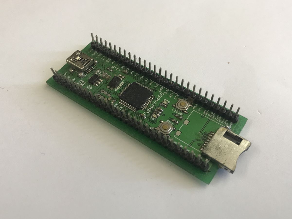
Project page: https://www.fubarino.org/sd/
Related topic: Test of the KSGER STM32 V3.1S OLED T12 mini soldering station and soldering the Fubarino SD
Programmer used
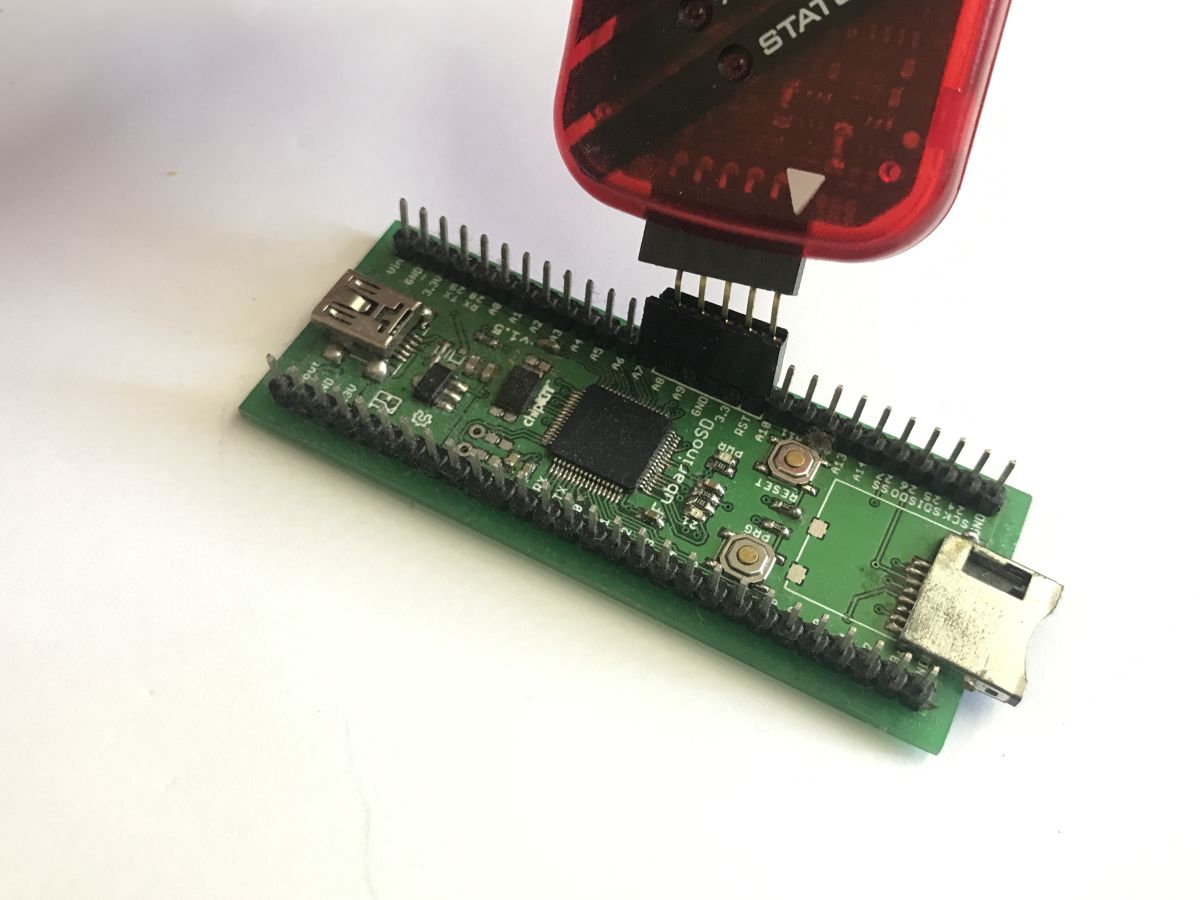
The PIC32MX does not come with a factory-loaded bootloader, and as I want to programme it from scratch, I need to use ICSP. ICSP (In-Circuit Serial Programming) is an interface developed by Microchip, allowing the microcontroller to be programmed and debugged whilst mounted directly on the target board. For programming via ICSP, I used the PICKIT3, a popular programmer that is also compatible with newer 32-bit microcontrollers. My board has clearly separated ICSP pins, so it’s easy to connect to it:
Compiler used
I’m using the pinguino-compilers package (p32-gcc.exe) on Windows. This is an open-source port of the GCC (GNU Compiler Collection) compiler, released under the GPL licence, compiled for the MIPS architecture. The Pinguino compiler files can be downloaded from their official repository: https://github.com/PinguinoIDE/pinguino-compilers . Thanks to this approach, I avoid the need to install Microchip’s XC32 environment – which is complex and often requires payment for higher versions – whilst gaining a solid foundation for experimentation.
PIC32MX795F512 memory map
Understanding the memory map is essential for bare-metal programming, as the MIPS architecture divides the address space into different virtual segments. The KSEG0 segment shown in the diagrams is cached and is used primarily for executing code from Flash memory, whilst KSEG1 bypasses the cache, which is essential for the correct handling of peripheral registers (SFRs) and the reset vector.
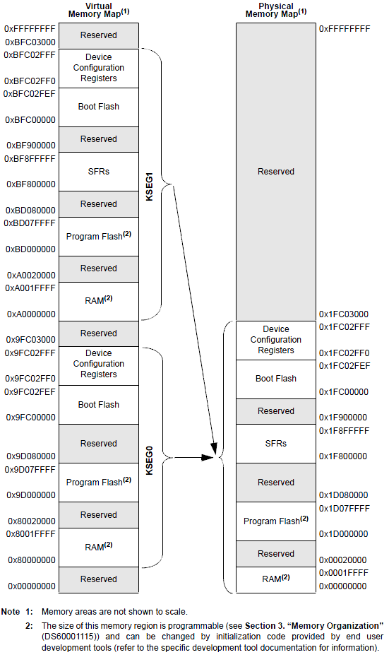
The first diagram illustrates the division of the 4-gigabyte virtual address space into kernel segments (KSEG) and user space (KUSEG). It shows that the KSEG0 (cached) and KSEG1 (uncached) segments point to the same 512 MB base area of physical memory. Fixed mapping (FMT) simplifies the architecture and eliminates the need to reconfigure the MMU after a reboot.
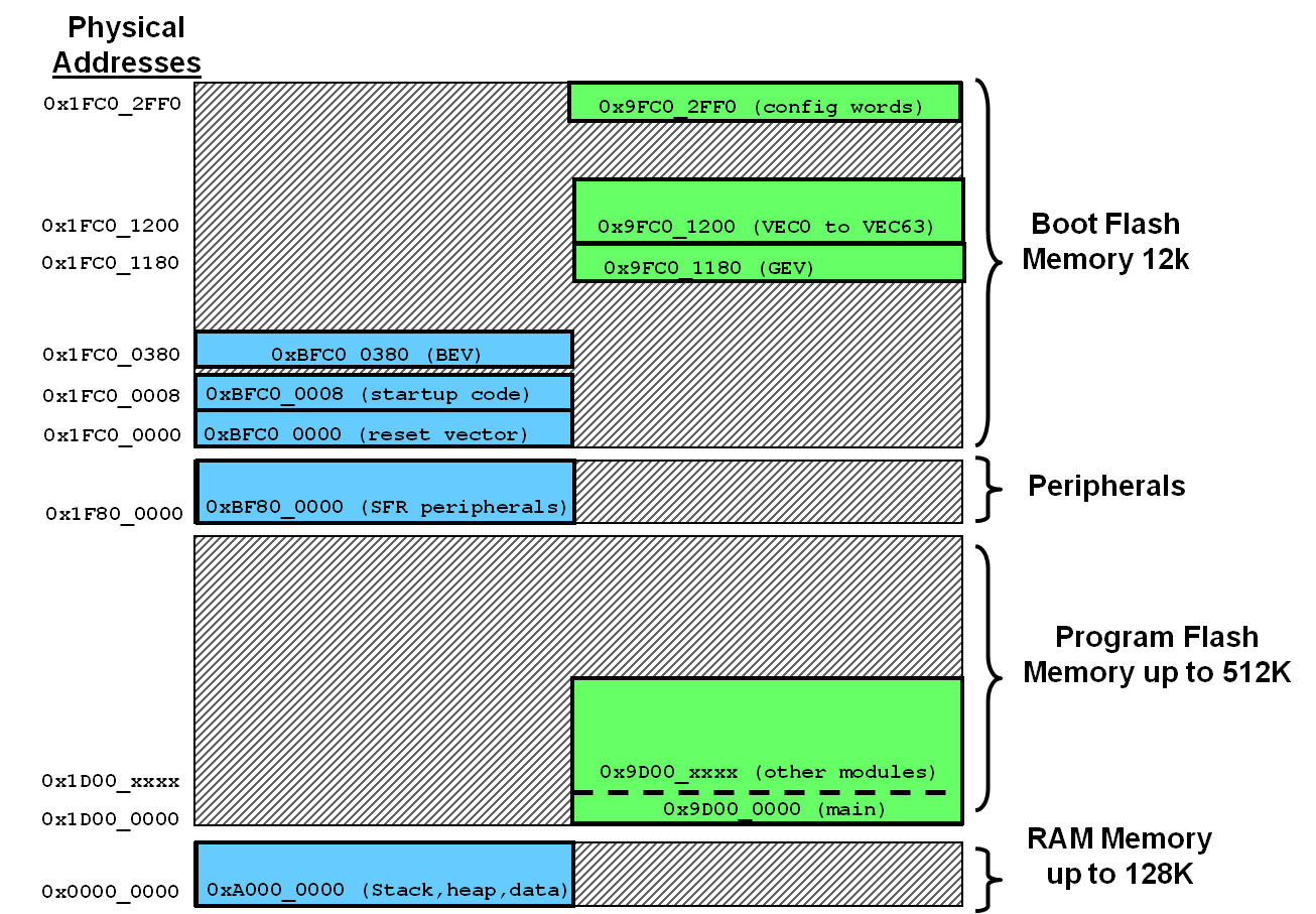
The second diagram illustrates the direct mapping of physical memory to specific virtual addresses. Program memory (Flash) with the physical address 0x1D000000 is read more quickly at the address 0x9D000000 (KSEG0) thanks to the cache. Hardware registers (SFRs), on the other hand, are accessed from the virtual address 0xBF800000 (KSEG1), which forces access to the physical hardware by bypassing the cache.
Source: https://developerhelp.microchip.com/xwiki/bin...view/memory-organization-overview/memory-map/
Getting started: what comes before the main function()
Every microcontroller programmer is probably familiar with the ‘main’ function, but did you know that this isn’t where the programme’s execution begins? After a reset, the processor jumps to the boot flash address. I need to provide it with the start-up code ‘crt0.S’, which initialises the stack pointer ‘$sp’ and transfers control to the C code.
Code: text
The above assembly code performs the minimum required to start the MIPS architecture. First, I load the end address of the on-board RAM (‘0xA0020000’) into the stack pointer register (‘$sp’), then I load the address of my ‘main’ function and jump to it (‘jalr’). Should my ‘main’ function ever return a value, the processor will enter a safe, infinite loop to prevent the code from wandering into unknown areas of memory.
First programme – flashing an LED
Rather than getting bogged down in complex systems, I’ll focus on the basics – making an LED blink in a simple way. In the MIPS architecture, peripherals are memory-mapped (Memory Mapped I/O). I access them using the non-cached virtual memory KSEG1 (the segment itself starts at ‘0xA0000000’, and the peripheral register block lies within it at addresses starting from ‘0xBF800000’). This is quite important for hardware, as read/write operations must go straight to the pins and not get stuck in the L1 cache. I’ve taken the register addresses themselves from the data sheet; below is an example for TRISE (0x6100):
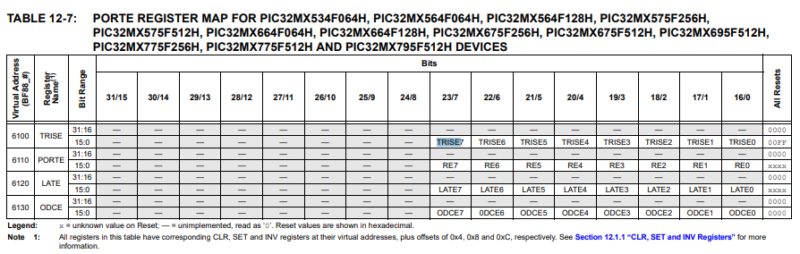
Instead of using Microchip’s header files (dozens, if not hundreds, of files), I define the pins manually.
In PIC32 microcontrollers, each port has three main registers:
1. TRIS (Tristate) – specifies the direction (1=Input, 0=Output)
2. PORT – used to read the pin state.
3. LAT (Latch) – used to write the pin state.
Furthermore, the hardware provides atomic registers: CLR, SET and INV. Writing to ‘LATEINV’ will cause a hardware bit inversion, which is significantly faster than the C operation (‘LATE = LATE ^ 0xFFFF;’).
For example, for TRISE, the result is 0xBF880000 + 0x6104, i.e. 0xBF886104.
Code: C / C++
The programme is very simple – it initialises the I/O, then, in a loop, toggles the pin and waits passively, wasting clock cycles – as simple as possible.
Linker script
In order for the compiler to know where to place the executable code and where to place the data in the MIPS architecture, I need the ‘pic32.ld’ file. In it, I’ve assigned the ‘.reset’ section and the interrupt vectors to the boot memory area (‘kseg1_boot_mem’), the main code to ‘kseg0_program_mem’, and the variables to RAM (‘kseg1_data_mem’). I have also defined the addresses for the configuration bits (‘devcfg’).
Code: Text
Build script
Here is a simple batch file that compiles my startup code and C code, links using pic32.ld, and finally extracts the necessary data to a ‘.hex’ file.
Code: Bash
Flash script
To programme the chip, I used the IPECMD tool from the standard MPLAB IPE package. I invoked the PICkit 3 programmer from the console (parameter ‘/TPPK3’), specifying my microcontroller model. The ‘/OL’ (Release from Reset) switch is useful here, as it releases the hardware Reset line once the upload is complete, allowing the programme to start without having to disconnect the programmer.
Code: Bash
Final presentation
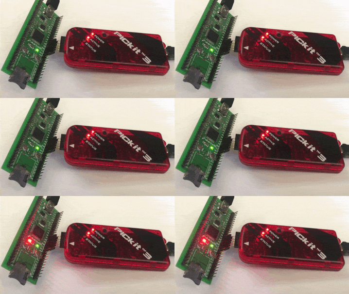
I’ve uploaded the code, a moment’s wait and… the LED is flashing!
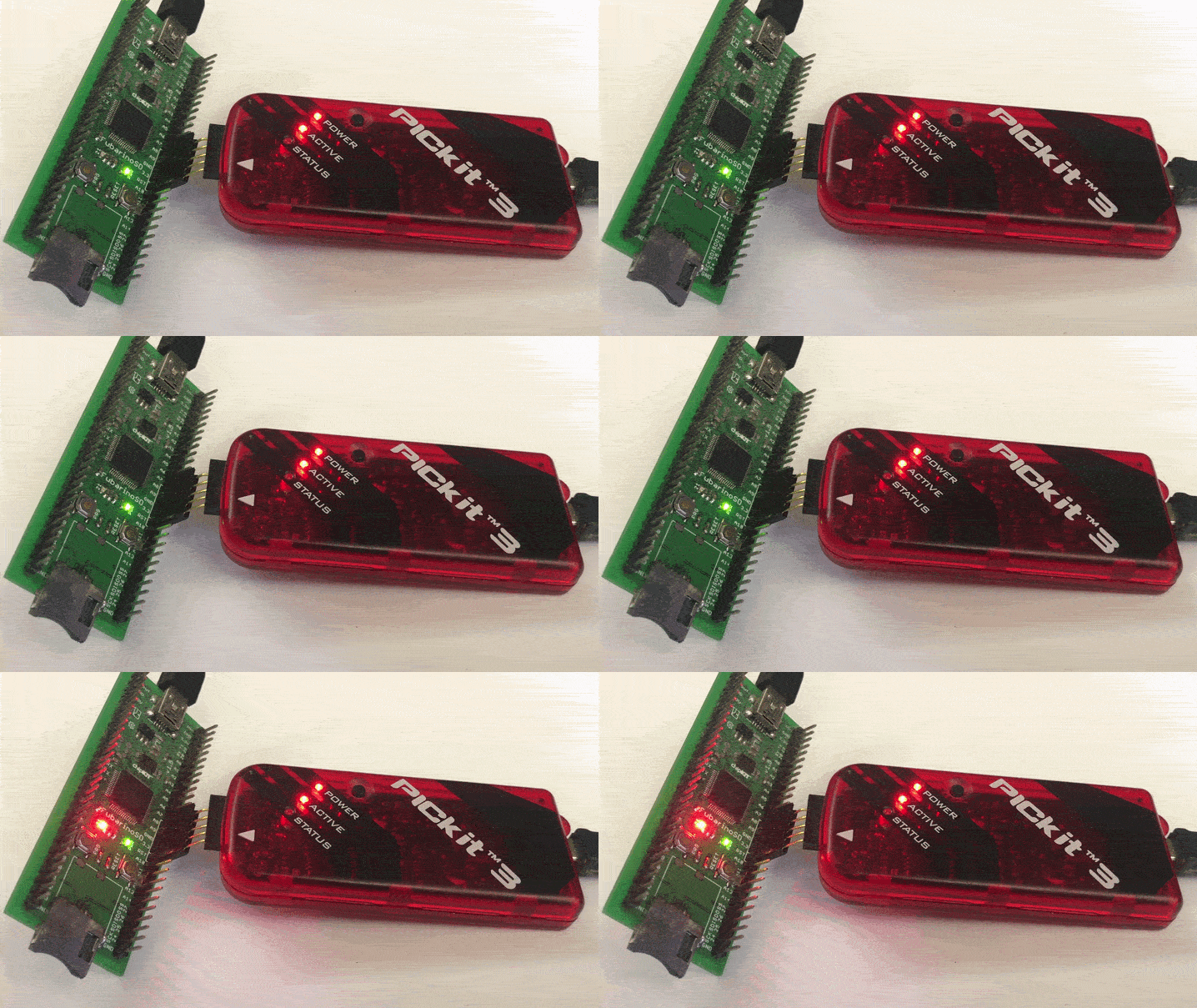
As you can see, headers and external libraries aren’t needed if you just want to make the LED blink. But what next?
Summary
To sum up, I’ve managed to get to grips with the MIPS core using just a dozen or so lines of code in pure C and a few configuration files. I compiled and flashed it using free command-line tools, without any major development environments. In the next part, I’ll try to run something more than just GPIO operations – perhaps interrupts? We’ll see. Have you ever tried programming microcontrollers from scratch in this way?
I’ve attached the results of my efforts in the attachment. You just need to correct the paths in build.bat and so on.
Cool? Ranking DIY Helpful post? Buy me a coffee.

