logo elektroda
logo elektroda
X
logo elektroda

Understanding 230V & 380V Current Phases: Wiring, Voltages, and Changing Direction of Power Motor

bandzior2 192788 61
ADVERTISEMENT
Treść została przetłumaczona polish » english Zobacz oryginalną wersję tematu
  • #1 5372435
    bandzior2
    Level 26  
    One thing puzzles me. How is it with these current phases? There are 4 cables on the pole. 3 phases and 0. 5. How is it going to a 380V power outlet? And so that's 3 phases + 0 + 0 protective. There is one phase + 0 to an ordinary 230V socket.
    So theoretically the phase is 230V. But how is it when there are 3 phases to a 380V power socket, and the voltage is 380V? It should theoretically be 690V, not 380V.
    And one more thing. Why is it enough to change one of the phases to change the direction of rotation of the power motor?
  • ADVERTISEMENT
  • Helpful post
    #2 5372492
    neo_dc
    Level 32  
    Phase-to-phase voltage = 400V (not 380)
    Voltage between phase and neutral = 230 V (not 220)

    You have 3 phases on the pole, working zero and protective zero (L1, 2, 3, N, PE)
    The working zero is derived from the star connection of the transformer windings (from the common point). Protective zero is ground.

    It is enough to change it because the individual waveforms are shifted to each other by 120 °, read the rest ;)
  • Helpful post
    #3 5372516
    Bogdanor
    Level 27  
    Cool logic: 3 phases = 690V, you added up the voltages of 230V. I wonder why you made this up. In the case of 3-phase circuits, the inter-phase voltage is used, not the phase-to-neutral voltage.
    ps. the phase itself has "nothing", only the potential difference between phase and zero, or phase and next phase, determines the voltage (potential difference).
  • #4 5372570
    Jasiek690
    Moderator on vacation ...
    Transferred from "Cheerfully."
  • Helpful post
    #5 5372667
    Hucul
    Level 39  
    Bogdanor wrote:
    ... For 3-phase circuits, the voltage is between-phase, not phase-to-neutral ...

    The voltage between zero and phase is also used.
  • #6 5372806
    Stary1952
    Level 32  
    Just read the book "Fundamentals of electrical engineering".
  • #7 5374245
    bandzior2
    Level 26  
    So how to combine 3 phases in one device, e.g. a 6kw motor, the voltage will be 400V and not 3x230V. Because it doesn't count as phase zero, phase zero, phase zero, only phase zero phase.
  • Helpful post
    #8 5375683
    neo_dc
    Level 32  
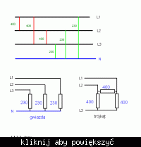
    Look here, I hope you can understand :)

    Understanding 230V & 380V Current Phases: Wiring, Voltages, and Changing Direction of Power Motor

    By definition, voltage is a potential difference, so you have to measure it between two points, if they are at the same potential then the voltage between them is zero V.

    I also painted the star / delta connections. Not every motor can be delta connected - it must be marked on the rating plate :)
    Not everyone is also starred - some of them are designed only for a triangle, they do not have a common output (to the N wire) outside, so it cannot be connected.

    I marked the tension with numbers.
  • ADVERTISEMENT
  • #9 5376201
    bandzior2
    Level 26  
    I more or less understood :)
  • ADVERTISEMENT
  • Helpful post
    #10 5376220
    Mariusz Ch.
    VIP Meritorious for electroda.pl
    Hello.

    neo_dc wrote:
    ......... Not everyone is also star-shaped - some of them are designed only for a triangle, they do not have a common connection (to the N wire) outside, so it cannot be connected.

    I marked the tension with numbers.


    With star connection, there is no need to connect the neutral conductor. The currents flow in phase conductors.

    Kisses
  • Helpful post
    #11 5378606
    Paweł Es.
    VIP Meritorious for electroda.pl
    Voltage waveforms in individual phases (measured in relation to the neutral wire (formerly zero)):

    $$L1=230*\sqrt{2}*sin(2*\Pi*50Hz*t)$$

    $$L2=230*\sqrt{2}*sin(2*\Pi*50Hz*t+120)$$

    $$L3=230*\sqrt{2}*sin(2*\Pi*50Hz*t+240)$$


    $$230V$$ - RMS value of the sine wave (it can be from 207 to 241.5V, i.e. from -10% to + 5% of the nominal value)
    $$230V*\sqrt{2}$$ - maximum value (amplitude) of the sine wave (325.22V)

    Phase-to-phase voltage (e.g. between L2 and L1):

    $$L2-L1=230V*\sqrt{2}*(sin(\omega t+120)-sin(\omega t))=230*\sqrt{2}*2*sin(60)*cos(\omega t+60)=230*\sqrt{2}*\sqrt{3}*cos(\omega t +60)$$

    The above transformation is based on the sine difference formula:

    $$sin(\alpha)-sin(\beta)=2*cos(\frac{\alpha+\beta}{2})*sin(\frac{\alpha-\beta}{2})$$

    For the considered phases:

    $$\alpha=\omega t+120$$
    $$\beta=\omega t $$


    $$\omega=2*Pi*50Hz*t$$

    RMS value of the interfacial tension

    $$230*\sqrt{3}\approx398.37$$ [V] (Max.value 230 * 1.73 * 1.41 = 561V)

    As for the motor, these three voltage waveforms supplying the windings of the AC motor cause (forcing the current flow in the coils) a rotating magnetic field, which "snatches" the rotor behind it (interacting with its magnetic field). Depending on the order of the maxima of the currents in the windings, the field rotates to the left or right.
    Swapping any two phases causes a change of direction

    The diagram below shows how the maxima move before and after the phase change (of course this is a simplification compared to what is happening in the engine, but you can see that the direction of travel changes)

    M - maximum current

    1 2 3
    M
      M
        M
    M
      M
        M
    M
      M
        M
    
    1 3 2
    M
        M
      M
    M
        M
      M
    M
        M
      M
    M
    
  • #12 5378731
    neo_dc
    Level 32  
    Mariusz Ch. wrote:
    Hello.


    With star connection, there is no need to connect the neutral conductor. The currents flow in phase conductors.

    Kisses


    And no equalizing currents do not flow through the neutral conductor in this case?
    I've always thought this and was taught this way to plug in, but I'd love to learn something new :)
  • #13 5384937
    Quarz
    Level 43  
    Hello,
    neo_dc wrote:
    Mariusz Ch. wrote:
    Hello.


    With star connection, there is no need to connect the neutral conductor. The currents flow in phase conductors.

    Kisses


    And no equalizing currents do not flow through the neutral conductor in this case?
    I've always thought this and was taught this way to plug in, but I'd love to learn something new :)
    A properly constructed three-phase asynchronous induction motor - with symmetrical supply - practically constitutes a symmetrical load for the source.
    However, it is an open secret that in such a case the equalizing current in the neutral conductor will not flow, and in the absence of it (a three-wire star system), there will be no asymmetry in the phase voltages of the receiver.

    best regards
  • #14 5605144
    domelek202020
    Level 12  
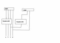
    And I have a different question. I have 1-phase and 3-phase sockets at home. How it looks in the switchboard. Usually, power supply in sockets, i.e. 230V, is it just a pulled out phase of these three? Is there a separate 3-phase cable and a separate 1-phase cable to the building? Is it like the picture? Can 220V lines be pulled from any phase? You can divide them, i.e. that on one floor the 230V line will be from one phase and on the other from the other or the third?


    Understanding 230V & 380V Current Phases: Wiring, Voltages, and Changing Direction of Power Motor


    best regards
  • #15 5605596
    bandzior2
    Level 26  
    There is no separate cable. 230V is taken from which phase. As you say, on different floors a different phase can be connected so as not to overload one.
  • #16 5717148
    MW-750
    Level 12  
    Unfortunately, old age is not joy - knowledge does not come to mind as it did several decades ago - so please do not be surprised by my questions. Now, to understand something, I have to see with my eyes what and where it goes, and invisible things like electricity are a mystery to me.
    1.4 cables come to the house (probably phase1, phase2, phase3 and zero)
    2.I have 3 large fuses on the main board - so I'm guessing that between 1 and 0, between 2 and 0 and between 3 and 0? So there are 3 phases of 220V each
    3. The garage has a 380V 3-phase power supply with 4 cables as at the entrance to the house. I bought a 3-phase saw but it has 400V which according to the store is the same as 380V ??? but it has 5 cables for the plug and is supposed to fit easily into my 4-wire installation - 380 + 400 is probably a rounding? but I don't really understand how a 4-cable installation is supposed to fit seamlessly into a device powered by 5 cables.
    4. According to the star-delta diagrams drawn above, I conclude that there are 230V three-phase motors and 400V three-phase motors ??? I am asking for this because in the same store there is a 220V saw with the same power and the seller said that if you also have 380V, it is better to take 380 because it will not load one fuse 220 but the current consumed will be divided into 3 fuses and then the fuses can be smaller and they will not heat up so much, and besides, 380V with the same rated engine power as 220V is stronger than it ????
    5. Why, according to the figures above, 230 + 230 = 400 and not 460?
    6. Where should I get the missing fifth wire for connecting the saw in the garage and what is it needed for?
    7. Does the sequence of phases (wires) in the plug matter?
    8. that is, looking at the above drawing - my current 400V saw has a TRIANGLE system because it would not be 400V in the star? And where is the ground or zero connected in the triangle connection drawing? Why for a 3-phase installation according to these drawings, you can use a 3-core cable, once a 4-core cable, and according to the saw that I have purchased, even a 5-core cable ???? Is the 3-phase installation not the same everywhere and if not what for (advantages and disadvantages) ???
    I am asking for help because I have a saw that I cannot use because I do not know how to connect it "without any problems" with my installation and thank you in advance for your help.
    PS.
    I am asking for simple answers, because the formulas and elements presented by someone do not tell me anything and I did not understand any of them.
  • #17 5717177
    neo_dc
    Level 32  
    So:

    1. You think well
    2. You think wrong. If they were between phase and zero, they would burn out immediately (the fuses are plugged in series with the receiver). They are like in the picture:

    Understanding 230V & 380V Current Phases: Wiring, Voltages, and Changing Direction of Power Motor

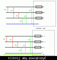
    3.6. Figure above. You have an old (4-wire) system at home. Now a new one (5 wires) is used. The fifth conductor is ground (so-called protective zero). All devices manufactured now use this system (if, of course, their construction requires grounding).

    Why higher voltage? If you remember that one year there was a change in the mains voltage (increase) - the voltage of 220V was increased to 230V and 380 to 400V. Old voltage devices will operate with a higher voltage (at least the vast majority of them).

    As for the fuses, the seller was actually right. The three phases are evenly loaded, so there is less current flowing in each of them than would be to use only one phase.

    7. Yes, it does. The saw will spin the other way. If there is no right-left switch, you have to swap any 2 wires phase with each other (thin pins in the plug). DO NOT SWAP PHASE WITH ZERO!

    The saw motor can be considered a little bit, without disassembling the device you cannot be 100% sure (if it is not stated on the plate). Although, as a rule, low-power motors are delta-connected (they do not have heavy starts).

    What about the protective conductor? Install a new socket in the garage and bridge the protective zero with the working one in the socket. The equipment will work, but I don't know how it relates to electric shock protection, so it's better for my colleagues to say something here.
  • ADVERTISEMENT
  • #18 5720607
    MW-750
    Level 12  
    Thanks for the quick reply. Some of my doubts have been dispelled, but not all. I would like to know more:
    1. According to the previously drawn star diagram, is it a 230V 3-phase motor? I am asking for this because in the same store there is a 220V saw with the same design, power and price as my 400V.
    2. Is the 230V 3000W motor weaker than 400V 3000W?
    3. I found one topic on this forum where it says that you can bridge 0 with mass, but only in one case. Unfortunately, it is a bit unclear in this thread and I cannot understand if it can be done in a 4-wire device to fit a 5-wire installation or vice versa - i.e. in a 4-wire installation to match it to a 5-wire device.
    4. Where is the grounding coming from - probably not from the power plant? If not, then in some simple way I could connect the earth electrode, for example, to a central heating pipe or dig into the ground and the issue of the 5th cable would be solved?
    5. if the sequence of phases (wires) in the plug is important, why can ANY phases be changed and not in some specific order? For example, the required order is 123, so to reverse the engine speed it should be 321 and not 132?
    6. Where in your triangle connection drawing is ground or zero connected?
    7. Why for a 3-phase installation, according to your drawings, you can use a 3-core cable once, and once a 4-core cable, and according to the saw that I have purchased, even a 5-core cable ???? Is the 3-phase installation not the same everywhere and if not what for (advantages and disadvantages) ???
  • #19 5720712
    bandzior2
    Level 26  
    3. You read these pictures wrong. The voltage between one phase and the other is 400V and the voltage between phase and neutral is 230V /
    4. Earthing goes from the transformer on the poles. Every few poles goes down to the ground.
    6. To change the movement of the motor the other way, it is enough to swap one phase with another. It is so and it will be and it was :)
    7. 3 = phase motors do not need zero or ground.
    8. Because the 2 extra cables are (neutral and ground). They fulfill a protective function. If the device is in the field and is earthed, e.g. a metal device with a metal table to the ground, it is not necessary to connect the earthing cable.
  • #20 5720841
    MW-750
    Level 12  
    Sorry, but after reading some other topics of this forum in the meantime, I found out some interesting things for me and changed a bit of my previous post without noticing that on the other side there was already an answer to it and there was confusion with the order of numbers.

    bandzior2 wrote:

    The earthing goes from the transformer on the poles. Every few poles goes down to the ground.
    Because the 2 extra cables are (neutral and ground). They fulfill a protective function. If the device is in the field and is earthed, e.g. a metal device with a metal table to the ground, it is not necessary to connect the earthing cable.


    So, can I release the mass of the device into the soil?
    The mass is known what it is for - and what is ZERO for and where does it run (power plant, nearest transformer or soil)?

    What about the rest of my questions:
    1. According to the previously drawn star diagram, is it a 230V 3-phase motor? I am asking for this because in the same store there is a 220V saw with the same design, power and price as my 400V.
    2. Is the 230V 3000W motor weaker than 400V 3000W?
    3. I found one topic on this forum where it says that you can bridge 0 with mass, but only in one case. Unfortunately, it is a bit unclear in this thread and I cannot understand if it can be done in a 4-wire device to fit a 5-wire installation or vice versa - i.e. in a 4-wire installation to match it to a 5-wire device.

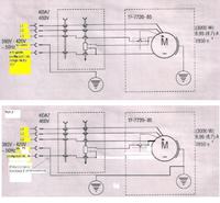
    More and more my doubts are resolved and if it goes on at such a pace, today or tomorrow I will start a new equipment, i.e. the Dedra 7727 circular saw. I enclose a diagram of its connection with 4 decoded cables and a question about the fifth-last cable. I know that the saw has a thermal switch and two buttons 1 and 0.

    Understanding 230V & 380V Current Phases: Wiring, Voltages, and Changing Direction of Power Motor

    Unfortunately, the factory did not give any description for it, and in particular did not explain how to connect the saw to a 3-wire or 4-wire network.
  • #21 5720958
    neo_dc
    Level 32  
    The engine has 3 coils. If they are designed for 400V voltage, they can be connected in a delta (see, each of them will be 400V) and star-shaped, but then it will be weaker (there will be 230V on each coil).

    If, on the other hand, the engine has 230V coils, it can only be connected in a star (if we connect it in a triangle, we will burn the engine).

    I am talking about 3-phase motors. There is probably a 230V 1-phase saw in your store. Theoretically, power is power and it shouldn't be weaker, but I have never checked things like this before.

    As for the phase sequence, see:

    123 123 123 123 - this is how the voltage on individual phases goes, if we change the voltage, see:

    132132132132 - do you see? Also it's 321, no so it doesn't matter :)

    You can make an earth electrode yourself - as you say, a flat bar is buried into the ground. Unfortunately, it must be done at an appropriate depth, because the earth electrode must have as little resistance as possible, it must be checked with a special instrument. In a word - the saw itself is not worthwhile.

    You will always connect a 4-wire device to a 5-wire installation - the protective conductor (PE) is not used then.

    Bridge both the N and PE conductors and connect the saw.
  • #22 5721239
    Wirnick
    Level 30  
    Hello.
    For MW-750. Compare the drawings.
    Understanding 230V & 380V Current Phases: Wiring, Voltages, and Changing Direction of Power Motor
    When the system is powered from the TNC network, local earthing is not performed.
  • #23 5721303
    MW-750
    Level 12  
    Almost everything is clear. There is only ZERO left - where does it run on the side of the network (power plant, nearest transformer or to the soil as mass) and where does it go on the engine side (see my diagram)? could the thermal switch cut off 1 winding and switch it to zero? So zero would be very important at this point. And what about this power - why did the store say that 3000W 3-phase is stronger than 3000W 1-phase.

    Wirnick wrote:

    For MW-750. Compare the drawings.


    In this case, the problem would start - I would not like to interfere with the installation of the device, if only for this reason, so as not to lose the warranty. I was hoping that everything would be successful at the level of mixing with the plugs and cables in them :cry:

    Understanding 230V & 380V Current Phases: Wiring, Voltages, and Changing Direction of Power Motor

    And would such a simple solution work? The equipment will work? If so, in this case I will avoid rummaging with electricity (I will fix the plugs away from the electricity myself :D ), calling an electrician (cost) or voiding the warranty of the device (I will not rummage in it).

    By the way, I will ask - why, as others on this forum write, in the event of a power failure in one phase, the engine is damaged?
  • #24 5744159
    MW-750
    Level 12  
    I made a cable according to my last diagram and the saw works. So I am waiting for information on previously discussed topics:
    1. 220-380 power comparisons
    2.what will be with the thermal switch from my diagram with the current settings
    3. if and why the engine breaks down due to the lack of one phase.
  • #25 5744205
    Paweł Es.
    VIP Meritorious for electroda.pl
    1. 220-380 power comparisons

    The power drawn from the network is the same in both cases, the difference will only appear in the supply currents (and thus in the cross-sections of the required cables)

    To obtain the same power at a lower voltage, a greater current must flow through the wires, requiring larger cross-sections of the wires.

    The 230V saw is so much more convenient that in many homes only one phase is available (not all of them have three-phase connections).

    A three-phase motor may have more shaft torque than a single-phase motor, but this is difficult to say without knowing exactly all the parameters of both motors.

    3. if and why the engine breaks down due to the lack of one phase.

    With the current three phases, there is a uniform rotating field in the stator of the motor and it moves confidently. The interaction of the rotor and the stator (inducing counter-voltage in the stator) causes the motor to consume less current at nominal speed than it would only result from the voltages and impedance of the windings.

    In the absence of one phase, the motor may not start (unless it is mechanically moved WHICH I DO NOT RECOMMEND, especially in the case of a saw) and when it starts, it will run unevenly and with less torque (i.e. the drive will be weaker).

    If the motor does not start, the windings take a much larger current, which with a badly set thermal switch may cause overheating of the windings, which is manifested by damage to the insulating enamel on the winding wires and interturn short-circuits -> motor to be replaced or winding
  • #26 5761522
    MW-750
    Level 12  
    WHAT ABOUT MY CONNECTION DIAGRAM? The thermal sensor is drawn on the engine? What does he disconnect and what does he switch to? What about the switch assembly - there is also something like a resistor or a coil and what does it switch on and off? Does my cable have the correct connections to the saw according to my diagram? I am interested in this because the engine is hot after an hour of operation and the thermal switch has not worked even once. Maybe it is not the switch-off temperature yet, maybe the thermal switch is defective, or maybe the missing PE wire causes the switch to not work? I work with my soul on my shoulder because I don't know if everything is OK - give me a hint.
  • #27 5772297
    neo_dc
    Level 32  
    Bridge the zero with the PE wire (casing) - in the event of a breakdown, it will protect you against electric shock. It looks like the saw has a built-in residual current circuit breaker and when we have 5 wires, it protects the user against electric shock.

    If the saw gets hot, check the manual how much it can work - often the current Chinese devices cannot work for a long time. The engine should not be more than approx. 70 - 80 * C
  • #28 5775803
    ektryk-ko
    Level 10  
    WHAT ABOUT MY CONNECTION DIAGRAM? The thermal sensor is drawn on the engine? What does he disconnect and what does he switch to? What about the switch assembly - there is also something like a resistor or a coil and what does it switch on and off? Does my cable have the correct connections to the saw according to my diagram? I am interested in this because the engine is hot after an hour of operation and the thermal switch has not worked even once.
    -------------------------------------------------- -------------------------------
    -------------------------------------------------- -------------------------------
    Currently used saws most often have the function of braking after switching off. This may cause the engine temperature to rise slightly. It may also overlap with a bit of over exploitation of the device.
    In non-professional devices, the power of the device is not always well suited to continuous operation. There may be, for example, too low engine power in relation to the saw diameter or ..... it is not known yet what. You asked for a wire that is disconnected by a thermocouple. I can see that the motor is switched on with a contactor, and the contactor is controlled by a coil, one pole of which is disconnected by a thermic. Activation of the thermistor causes no control of the coil and as a result all power phases are disconnected. You asked why a 1-phase and a 3-phase motor with equal power ratings can have different powers. Theoretically, it can be proved, but I will say this: it is about voltage drops. Someone has already explained it to you on this topic. Connect, for example, a 230v extension to such a saw only with a 1-phase motor. the pre-bed is, for example, 35m. and it is, for example, 3x2.5. the current flows through 2 wires and you get power from 230v. you now have 35 m of 5x2.5 cable. The current flows through the wires and the power is obtained from the voltage of 400v. I don't know how to picture it to you otherwise.
  • #29 5776939
    MW-750
    Level 12  
    Thanks to everyone for your help and answers. Now I have a new problem.
    The saw did not come for a long time. She heated herself up, heated herself until she stopped walking. Not once did the thermal switch trip out. When firing, the engine hums and does not spin. I waited a few hours for it to cool completely and it still grumbles and doesn't want to surprise. After a longer support of the shield by hand, the engine started and walked normally, and after turning it off, it still growls and does not spin and within a few minutes the engine heats up very much. After removing the motor and removing the disc, the motor itself jerks, jumps, but when you turn the shaft, it will rotate after some time. When changing the power cables, the motor jerks and jumps in the same way, but in the opposite direction. I took the engine to the site. I wonder if it is not the fault of the thermal switch that it did not turn on and some winding overheated or if it is not the fault of my cable, e.g. that the thermal switch did not work because maybe the ZERO wire from my diagram should not be connected to the coil on the switch, but only on the mass? Why the thermal switch did not work even once - I mean my last diagram (the fact that it could be faulty or not connected, I understand). Now I have to wait 2 weeks for a response from the site. Uncut wood is wet in the yard, the dry supply is running out and soon there will be nothing to burn in the stove and PLN 650 melted :cry:
  • #30 5777288
    ektryk-ko
    Level 10  
    Don't have some common multimeter? Check: / if you have the motor dismantled, it is easier for you / if there is any breakdown from the ends of the motor windings to the ground. You can easily miss interfacial interphases. No burnt smell from the engine? You won't burn an engine as easily as it has 3 - phases in its power supply. This again would have to be measured not only if it has 3 phases but if they are of different phases. If, for example, you ever had a phase-to-phase short circuit on the section from the protection of the power supply cable to the engine, it may happen that one fuse will burn out and the wires will join, and by checking the phases to zero, there will be voltage everywhere, and the 3-phase motor will be damaged. Normally, the lack of N or PE in the power supply of a 3-phase motor has no effect on its damage.

Topic summary

The discussion revolves around the understanding of 230V and 380V current phases, particularly in relation to wiring configurations, voltage levels, and the operation of three-phase motors. Key points include the clarification that the phase-to-phase voltage in a three-phase system is 400V, while the voltage between phase and neutral is 230V. The necessity of changing one phase to reverse the direction of a motor is explained through the concept of phase shift in the alternating current (AC) waveforms. The conversation also touches on the implications of connecting devices to different voltage systems, the importance of grounding, and the differences between star and delta connections in motors. Additionally, users share experiences with specific devices, troubleshooting issues, and the significance of thermal switches in motor operation.
Summary generated by the language model.
ADVERTISEMENT