logo elektroda
logo elektroda
X
logo elektroda

Best Methods for Determining Phase Sequence in a 3-Phase Socket for Hydraulic Pumps

efenix 67779 16
ADVERTISEMENT
Treść została przetłumaczona polish » english Zobacz oryginalną wersję tematu
  • #1 7696525
    efenix
    Level 10  
    Hello,

    I am asking for a hint with which methods are the best to determine the phase sequence in the 3-f socket. It is important to me to be sure that there is the correct sequence in the socket (e.g. for switching on the hydraulic pumps in the machine). Thank you for your help.
  • ADVERTISEMENT
  • Helpful post
    #2 7696574
    bava
    Level 12  
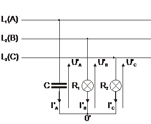
    With the help of a capacitor and incandescent lamps:

    We mark one of the terminals with L1 and connect the branch with a capacitor to it. We connect branches with bulbs to the other two terminals. The L2 terminal is the one in the branch of which the bulb shines brightly, while the L3 terminal is the one in whose branch the bulb shines with a weaker light.

    With the help of a choke and light bulbs:

    Connect the branch with a choke to the terminal previously marked with a choke, to the remaining terminals of the bulb.
    The L2 terminal is the one in the branch of which the bulb shines with a weaker light
    The L3 terminal is the one in the branch of which the bulb shines more intensely.

    Both systems are connected in a star pattern.
    greetings
  • ADVERTISEMENT
  • #4 7699427
    Georges
    Level 15  
    Hello. Cheaper than the meter, the phase sensor will fall out in sequence. You will be sure that the motor will turn in the correct direction.
  • #5 7700693
    sq9jjh
    Electrician specialist
    Georges wrote:
    ... Cheaper than the meter, the phase sensor will fall out in the sequence ...

    Hello, what a new date this is " phase sensor with sequence "?
    Maybe an example? :D
  • Helpful post
    #6 7702003
    kkas12
    Level 43  
    Hello!

    Quote:
    You will be sure that the motor will turn in the correct direction.
    Let's not write such things. This is not always the case.
    The fact that the directions of rotation in the socket or in the sockets are standardized does not mean that every device or motor connected to it will spin in the same direction.
    Two identical devices plugged into the same socket do not have to spin in the same direction.
    Such determination of the direction in the sockets is good when it is used by the receiver / receivers adapted or assigned to this socket.
  • Helpful post
    #7 7702283
    Madrik
    moderator of Robotics
    Not only. It facilitates the subsequent service of receivers. It is enough to change the wires on the receiver plug once and we have the same direction of rotation all over the area.
    For casual receivers, which cannot be modified, it is enough to make an adapter from the socket and plug, with the changed phase sequence. It is also a good solution for someone who often drives with his own receiver on different terrains. Either plugs into the socket directly or through an adapter - without a combination.
  • #8 7702321
    kkas12
    Level 43  
    Hello!

    The colleague did not come up with anything new.
    Or maybe you should remember the old, proven way, when a self-respecting designer and electrician preceded the power socket with a switch? Of course, it could also be a spin-reverse switch.
    And equip the device with appropriate gadgets that prevent it from starting when the speed is incorrect.
  • #9 7702500
    jekab
    Level 23  
    Quote:
    And equip the device with appropriate gadgets that prevent it from starting when the speed is incorrect.

    You are right, no one has come up with and will not come up with a device that by "proper" connection of the wires in the socket will guarantee that something will turn well.
    When it comes to gadgets, they exist, for example, in screw compressors.
  • ADVERTISEMENT
  • #10 7702516
    forestx
    Rest in Peace
    bava wrote:
    We mark one of the terminals with L1 and connect a branch with a capacitor to it. We connect branches with bulbs to the other two terminals. The L2 terminal is the one in the branch of which the bulb shines brightly, while the L3 terminal is the one in whose branch the bulb shines with a weaker light.
    - You can draw it / describe it more precisely - because I'm either blunt or ...
  • #11 7702570
    jekab
    Level 23  
    forestx wrote:
    bava wrote:
    We mark one of the terminals with L1 and connect the branch with a capacitor to it. We connect branches with bulbs to the remaining two terminals. The L2 terminal is the one in the branch of which the bulb shines brightly, while the L3 terminal is the one in whose branch the bulb shines with a weaker light.
    - you can draw it / describe it more precisely - because I'm either blunt or ...

    This is how it works, I checked, it gets a lot of asymmetry. I understand, but I can't understand
  • Helpful post
    #12 7702686
    Arturo2005
    Level 33  
    jekab wrote:
    Quote:
    And equip the device with appropriate gadgets that prevent it from starting when the speed is incorrect.

    You are right, no one has come up with and will not come up with a device that by "proper" connection of the wires in the socket will guarantee that something will turn well.
    When it comes to gadgets, they exist, for example, in screw compressors.


    Best Methods for Determining Phase Sequence in a 3-Phase Socket for Hydraulic Pumps
  • #13 7704403
    romix195
    Level 12  
    He can just plug in the pump and check if it is in the right direction, and if not, reverse the phases.
  • ADVERTISEMENT
  • Helpful post
    #14 7707745
    bava
    Level 12  
    Best Methods for Determining Phase Sequence in a 3-Phase Socket for Hydraulic Pumps
    R1 = R2 = 1 / wC
    We turn the system on for a short while so that the bulbs only flash because, as one of my colleagues said, there is a large asymmetry in the system, the next phase after the phase with the capacitor on is the one in which the bulb "flashes more"
    I hope everything is clear now, best regards
  • #15 7707828
    forestx
    Rest in Peace
    OK - I have not read that it is fastened into a star - everything is clear.
  • #16 7773410
    efenix
    Level 10  
    Thank you for your interest and help.
  • #17 7773540
    retrofood
    VIP Meritorious for electroda.pl
    I close the topic.

Topic summary

The discussion focuses on methods for determining the phase sequence in a 3-phase socket, particularly for hydraulic pumps. Various techniques are suggested, including using capacitors and incandescent lamps to identify the terminals based on bulb brightness, and employing a choke with light bulbs for similar results. A phase sensor is recommended as a cost-effective alternative to meters for ensuring correct motor rotation direction. The importance of standardization in socket connections is emphasized, although it is noted that identical devices may not always rotate in the same direction. Practical solutions such as using adapters for phase sequence modification and incorporating switches for reversing motor direction are also discussed. Visual aids and links to diagrams are provided to clarify the methods.
Summary generated by the language model.
ADVERTISEMENT