Hello,
uish wrote: Hello all.
I have 3 three-phase sockets in the Garage, one for 4 wires two out of 5. They were once connected by an electrician, I assume that it's good. Everything worked.
Following their connections, I made more. To make things easier for the future, I did it using a small switchgear with five rails on which there were individual phases. Unfortunately, I did not describe the rails. I am writing unfortunately, because my brother-in-law wanted to connect something, he took a colleague of "expert" from beer, who, like every mega expert, first found everything sucked, then he turned it on and finally said it could not be done. He chewed a pair of beers at the same time and wrapped himself up.
I stayed with the cables, at the entrance to the layout, which were located just after 50, all have the same color. (super on copper)
Tell me how to sort it back now
How to recognize 0
How to recognize L1,
How to recognize L2,
How to recognize which is L3.
It would be nice if it was a method at most with the use of a simple meter of up to PLN 50 (I have it) without what advanced mega devices, because on YouTube a lot of smarters with equipment for a thick money that do not require thinking, and nothing like how to do it like the old electricians.
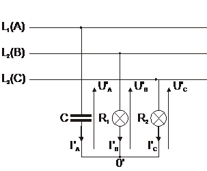
the simplest - and known in Electrical Engineering since the existence of Three-Phase Systems - is an indicator / indicator composed of two bulbs and a capacitor, with a wiring diagram as follows:

The above diagram was taken from the topic about it
THERE And which arrangement everyone - although every electrotechnics knows a bit - can assemble on their own.
I only pay attention to health and safety, because we are dealing here with values of tensions dangerous to human health and life. Therefore, NO preserve, and the elements of this phase sequence indicator are enclosed in an insulated casing and the wires lead outwards in a suitable - double - insulation.
And the arrangement itself
connect to the terminals -
L1 .
L2 L3 - three-phase network
in a state without voltage , and only after connecting the wires of this indicator, we turn on the voltage, eg switch - and what should be at the input.
Now a few words about the indicator itself; Tungsten filament lamps are generally available for nominal voltage of 230V, but in this system there is asymmetry - this is the one used here to indicate Phase Sequential Phase Sequence - that's why (and what I know from my own experience) one such bulb will not live there for a long time on one of the bulbs, with a Wired Voltage equal to 400V, there will be a voltage much higher than 230V.
Experience shows that the lower the rated power of a light bulb, the higher it withstands the voltage above its nominal value.
But even typical signal bulbs - on switchboards - 230V / 15W will not last long in this system.
Therefore, it is a reasonable solution to connect two identical bulbs in a row - or, more preferably, to connect a resistor with power and resistance similar to the corresponding bulb parameters and its nominal voltage (it should not be forgotten that the bulb is a Non-Linear Resistor) ).
It is obvious that the lower nominal power of the bulbs used is the better for this application, which is why alternatives to the above-mentioned - and generally available - 230V / 15W bulbs with E14 thread are missing.
The theoretical condition for the correct selection of capacitor capacitance values - for this indicator - is the equality of the resistance value and its reactance for the 50 Hz frequency.
Assuming that they will be used, w / in, two light bulbs connected in series, then we have their nominal resistance value:
R WITH N = U N ? / P N = (230 + 230) ?V? / (15 + 15) = 7.0533 (3) kohm.
However, the value of the capacity
C capacitor from the formula:
C = 1 / (2 o ? o f o X C ) = 1 / (2 o ? o o 50Hz 7.0533 (3) o 1000?

o 4.51290008767190 = 10 ^ (- 7) F
The closest - and produced - is a capacitor with a capacity of 0.47?F and it should be a capacitor for a nominal operating voltage of 630V.
At the end of the words, a few words about wires and bulbs would be clearly known when we deal with the Phasing Centrifugal System, and when with the Left Turning Centrifugation Phase.
Here I only mention that in the Theoretical Electrotechnics it is assumed to be a spinning system, Centrifugation Phase is such an arrangement,
in which the order of centrifugation their Directions is ANYTHING to the direction of Clock Clues Movement, - but such a clock:


BUT never like this:


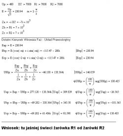
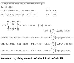
In the above-mentioned topic this question has not been answered unambiguously (it was not given when, which light should be brighter) - that's why the topic is still open - so in a slower moment I will be tempted to count the voltage values, for both cases, and I will inform you here.
greetings
EDIT hours 17:45
Promised calculations - made with the use of MathCAD - showing the differences in the voltage values on the bulbs when changing the Phase Spin Order in the Three-Phase Symmetrical Power System:


