logo elektroda
logo elektroda
X
logo elektroda

Comparing Different Schematics for CAE3+SE Guitar Preamplifier - Impact on Sound?

blurecon 12087 9
ADVERTISEMENT
Treść została przetłumaczona polish » english Zobacz oryginalną wersję tematu
  • #1 8208611
    blurecon
    Level 10  
    Hello. (I hope I chose the right section on the forum)

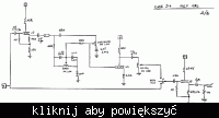
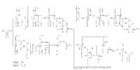
    I am going to assemble a guitar preamplifier, namely the little known (unfortunately) CAE3 + Se - Custom Audio Electronics (Bob Bradshaw). I was looking for schematics on the internet and it is quite poor, here's what I found:


    Scheme1:
    http://www.settoflames.com/CAE%203_SE.bmp


    Scheme2:
    Comparing Different Schematics for CAE3+SE Guitar Preamplifier - Impact on Sound?

    Comparing Different Schematics for CAE3+SE Guitar Preamplifier - Impact on Sound?


    I noticed that the diagrams differ to a large extent from each other - an additional seventh lamp (the original has 7). However, the diagram with 6 tubes is clearer and more understandable, what will be the difference in sound? And what about the voltage supplying the lamps? The diagrams are not perfect, so if someone would have something better, I would be very grateful. This preamp is my little dream, I will add that it is currently played by Steve Lukather himself.

    The diagrams should be pasted using the "Add image" option - please correct.
    / presidentwal /.
  • ADVERTISEMENT
  • #2 8208819
    sabringer
    Level 25  
    Yeah, Luke :D . You have my knowledge ;) . And Bob Bradshaw deserves a commitment.

    The first rule - no matter what the diagram says, it should work well for you and suit you. Therefore, do not be afraid of changes, because the diagram may be uncertain, or you will use slightly different elements (e.g. in the Lead channel I would use tantalum capacitors in cathodes, not electrolytes).

    The first scheme is being modified - pay attention to the author's notes, he got it right with him :D
    There is only the ejected EQ (Bass + Presence + Level), which is triggered "from the foot". + Dude added a 1M resistor (before the 22n input conduit of the last triode), which is 90% redundant.


    Basically the idea of this preamplifier - clean Fender channel, crunch ala "Atomic", distortion slightly under the SLO - generally with soft clipping, soft clipping. Independent scales for everything.


    Quote:
    And what about the voltage supplying the lamps?

    I don't understand the question - there is a power supply in the first diagram ;) . In this type of systems, it starts from around 300V (in points A, B, ...) There is no need to make an anode one weird.
    On the other hand, I would do a bit of a trick with incandescence - it gave constant / stabilized ones for the input tubes and slightly increased the heater potential of the follower tubes to reduce the heater-cathode voltage.
  • ADVERTISEMENT
  • #3 8209296
    blurecon
    Level 10  
    Hmm, in general, if I would, let's call it this version, it would be hard to do in the original then like something. That's why I wonder because I like how to twist things, and I love Luke, and this "handwritten" scheme is not fully understandable to me when it comes to some connections ...
  • #4 8209800
    Futrzaczek
    VIP Meritorious for electroda.pl
    The very idea of the preamplifier remains unchanged: chain-linked WK stages on the ECC83 (100-220k in the anode, 1-1.5k in the cathode, 1M leakage) + tone control + volume control.

    If the pattern you found meets the above criteria, it will work, as long as there is no gross error. The rest of the mysterious "sound" are details, such as the capacitance of the coupling capacitor or the shunting of the anode resistor with a capacitor.

    The power supply for the preamplifier is no secret. 1A / 1kV + 100uF + 1000 ohms + 100uF bridge in parallel with 220k / 5W and there is no way to make it malfunction.
  • #5 8211959
    blurecon
    Level 10  
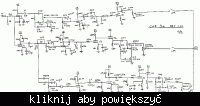
    I found something else like this:

    Comparing Different Schematics for CAE3+SE Guitar Preamplifier - Impact on Sound?

    This is probably a better version of the 'handwritten' scheme combined as a whole, it seems more understandable. I have a few questions, at the beginning I had a little contact with the preamplifiers and I am not a consummate electronics technician, I already have a few designs behind me and I would like to build this preamp, I hope that with the help of you and some of my colleagues, I will give quite advanced I will do it and I will do my job:

    1. In the diagram, the voltage inputs to the lamps are marked with letters from A to G, what is the principle and logic in it? I am asking because the V2 lamp has, for example, two different symbols B and G? And the third and fifth lamps are the same sources. What is the voltage distribution?

    2. The diagram is of course incomplete because there is no switch section, I read something about TTL as a mechanism but I do not fully understand it, I only noticed the Reed switch. And I think this will be the hardest thing. I read that it is quite complicated and requires a footswitch. Is it possible to introduce an ordinary manual mechanical three-position switch to change the channel? If so, in what way? This is quite a good solution because for now I only want to get sound, then I can play some integrated circuits. How does it work in general? (I assume that I will use the schema in this post)

    3. Where does the presence and modification of the schema come from?

    The rest is as 'comprehensive'

    That's it for now, I am attaching a package with photos of the "guts" of the original, maybe they will suggest something.

    Thank you in advance for your help
    greetings
    Attachments:
  • ADVERTISEMENT
  • #6 8212690
    sabringer
    Level 25  
    After all, you can always redraw the diagram "in your own way".

    You have a schematic of the power supply in "Scheme 1". Each letter has a similar potential and supplies 2 stages (or 2 repeaters for the sound reg.). They also have the function of influencing the bass response. Stick to the configuration from the last diagram, "by eye" I can see that it is ok ;) .

    2. false switching = stopping. There are no reed switches there, only LDRs (the best but expensive bastard :D ). Or something on cute JFETs. Relays like to knock (transients) and should be supplied with stabilized voltage.

    http://www.mif.pg.gda.pl/homepages/tom/misc.htm#Footswitch " target="_blank" rel="nofollow noopener ugc" class="postlink inline" title="" > http://www.mif.pg.gda.pl/homepages/tom/misc.htm#Footswitch

    Have a nice reading ;)
    Of course, you can use an ordinary switch and give a 2km signal through it and inside, but how inelegant ...

    It depends on how you want to put it together, you can try to make a "temporary" solution and no problem, but it's better to have fun while playing, there is no point in spoiling great equipment with laziness :D .


    3. Another name for Treble - the 3 knobs are for the EQ, and that is all in the diagram.


    Nice double-sided tile, Mesa reminds me :D . Which, unfortunately, means a whole lot of "invisible" couplings (capacitance of the pF order between paths) and you have to treat the scheme as a "base".
  • #7 8220517
    blurecon
    Level 10  
    I have one more question ... Are there and where can I buy such exotic capacitors and resistors as: 681, 47m, 47.5k, 0.003uF, 0.007uF and other even more "bizarre"? I found such on the diagram ...
  • ADVERTISEMENT
  • #8 8220977
    Futrzaczek
    VIP Meritorious for electroda.pl
    You will find it only you need to look for in a series of more precise resistors. The creator of this scheme probably did not quite know what he was doing or was illiterate - I do not know where the idea of giving the two halves of the lamp the same markings came from:?
    681 in the V6 cathode is probably 680 ohms. 47.5k, which are in the frame of this lamp, can be replaced with 47k without regret.
    The 0.007uF separating capacitor will have to be replaced with 6.8nF, which is normally sold.
    The capacitor marked as 47m is 47nF.
    475k, which is the leakage resistor of the control grid V6, should be replaced with 470k.
  • #9 8221608
    blurecon
    Level 10  
    Since the topic has been moved to the forum, beginners, I can ask some basic questions (at least I will expand my knowledge)

    1. What is this reed switch (by Baxandall) for? It just turns on this pre-equalizer? And how does it work ??
    2. How do LDRs work there, collect light from lamps? I am asking because the original uses these terribly expensive optocouplers (see photos), which are not listed in this diagram. Well, what is their task?
    3. Regarding the transformer. should have: ground, one 6.3V output for incandescence and 2x263V for the anodes, with relays for the future, but I do not know how much V ... Anyway, I found something like this on the network: http://sklep.lampyelektronowe.pl /? 79, tsl-100-001-network-indel-transformer
    will it fit?
  • #10 8228073
    blurecon
    Level 10  
    It's me again, I decided to limit myself to the clean channel for now, cut down the diagram and made adjustments:

    Comparing Different Schematics for CAE3+SE Guitar Preamplifier - Impact on Sound?

    There are only two places left with which I do not know what to do, I do not like the capacitance of the capacitors. By the way, I would like to ask someone experienced to analyze the scheme and say if everything is fine. Oh, and this unfortunate 6.8nF (0.007uF) separating capacitor was replaced with 47nF (it's like before other tubes)


    Best regards and I am counting on a patient reply, it is very important to me. All I can offer is to donate points, but I will also be very grateful for any help.

    Paul.

Topic summary

The discussion revolves around the assembly of the CAE3+SE guitar preamplifier, focusing on the comparison of different schematics available online. Users express concerns about the variations in the diagrams, particularly regarding the number of tubes and the clarity of the designs. Key points include the importance of adapting the schematic to personal preferences, the role of specific components like tantalum capacitors, and the power supply requirements. Questions arise about the voltage distribution for the tubes, the function of reed switches and LDRs, and sourcing specific capacitors and resistors. Participants share insights on modifying the schematics and emphasize the significance of maintaining the original sound characteristics while making adjustments.
Summary generated by the language model.
ADVERTISEMENT