logo elektroda
logo elektroda
X
logo elektroda

Audio Amplifier on Transistors: Stereo Conversion, 2x17V Toroid Transformer & 2M Capacitor Marking

Penio00 6795 16
ADVERTISEMENT
Treść została przetłumaczona polish » english Zobacz oryginalną wersję tematu
  • #1 16821119
    Penio00
    Level 7  
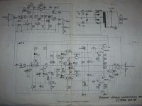
    Hello, I found a schematic of a mono amplifier on the internet and converted it to stereo. Is everything ok after my connection? Of course, I will make a symmetrical power supply and the transformer I will use is a 2x17v toroid. And what is the marking of the 2M capacitor? Audio Amplifier on Transistors: Stereo Conversion, 2x17V Toroid Transformer & 2M Capacitor Marking
  • ADVERTISEMENT
  • #2 16821159
    aaanteka
    Level 42  
    And what was that amplifier and in what class did it work? Seems like the correct diagram. However, I recommend modifying the schematic to that of the proven, good "Eltron 100" on slightly more modern transistors and you will have no problems and a pretty decent amplifier.
  • ADVERTISEMENT
  • #3 16821171
    Penio00
    Level 7  
    This amplifier, what I found, I only know about it that it is 30w, but I do not know the class or other specifications. Generally, I do not need an outstanding amplifier, but I need it for school as an analog circuit work.
  • ADVERTISEMENT
  • #4 16821203
    aaanteka
    Level 42  
    This may be enough, but you should consider how the stabilization of the quiescent current is carried out (the teacher may ask :D ).
    The most simple construction can be obtained on the old TIP142 / TIP147, BDX53 / BDX54, BDW83 / BDW84.

    Link
  • #5 16821237
    Penio00
    Level 7  
    The teacher is emm lazy to say. It does nothing in the lesson but requires. As for the projects, we already had one, and he only checked the board performance and operation, so I doubt he will ask for anything. So this scheme can be like this?
  • #6 16821285
    Anonymous
    Level 1  
  • #7 16821296
    Penio00
    Level 7  
    Now I'm a little confused. So I can use this schamt to build an amplifier or not.
  • #8 16821319
    Anonymous
    Level 1  
  • #9 16821335
    Penio00
    Level 7  
    I read what you wrote. But now my question. What amplifier should I make. I do not want it to be expensive to make because I will not use it on a daily basis, I will probably run it once in a while. It doesn't have to be very powerful either. But it must be on discrete elements

    Added after 1 [hours] 54 [minutes]:

    Ok, I found it already, whether it's good or bad, I hope that it will work and writes that Q3 and Q4 and IC are common for both channels and on the schamacie only the left channel is presented so I have to do literally the same as above to put these scams next to each other left signal to one right to the other or some other way to connect it. I would ask for a quick reply
  • #10 16821681
    aaanteka
    Level 42  
    You had said:
    - follow the "Eltron 100" diagram, and use, for example, newer transistors such as 2SC5200 / 2SA1943, or 2SC3858 / 2SA1494 in the complete power stage, or only two 2SC5200 or two 2SC 3858 in a pseudo-circuit [/url] complete, in the control stage 2SC4793-2SA1837,
    Audio Amplifier on Transistors: Stereo Conversion, 2x17V Toroid Transformer & 2M Capacitor Marking


    OR
    - in the cheapest version, use Darlington transistors like the cheap BDX53 / 54, which will simplify the design to a minimum. Another example diagram:

    Audio Amplifier on Transistors: Stereo Conversion, 2x17V Toroid Transformer & 2M Capacitor Marking

    ( of course you can use a lower supply voltage and BDX 53/54 - similar to one of the versions of the amplifier in Zodiac - generally Unitra used one, practically more or less developed scheme ;) ).

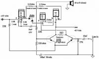
    The diagram you provided is a Sinclair 30 study from 1969 :D . And here's a little more about its design. and on ours forum .
  • #11 16821685
    Penio00
    Level 7  
    But above I wrote that I want something simple because it only gives back and get a grade .. I don't need 100w until. And would what I gave now be ok?
  • ADVERTISEMENT
  • #12 16821697
    aaanteka
    Level 42  
    I can see that my friend has a vague idea of what he wants to do. It is enough to use a slightly lower power supply and with lower efficiency, possibly correct the gain and have a colleague amplifier 10-20-30W. It is enough to look at Unitra's constructions, such as the amplifier in the mentioned Zodiac, later Tosca, or the Dior WS422 set amplifier.
    The amplifier from the BDX53 / 54 would probably have 20W / 8?. Also my friend does not like its simplicity?
  • #13 16821706
    Penio00
    Level 7  
    The main point is that I have a vague idea of what I want to do because the teacher himself does not teach us much. He will come to say what to say and his work is over. He said make an amplifier on discrete elements so much information about it. I found something else 10w amplifier that I posted above and is it ok good and whether in stereo it looks the same as the first one
  • #14 16821721
    aaanteka
    Level 42  
    Opinions have already been written about the project you have chosen, and here, as well as in the materials that were recommended. If you want to make a stereo amplifier, you must necessarily duplicate the entire amplifier path for both channels, i.e. the voltage and current stage of the power amplifiers are performed twice. At most, the power supply is common, i.e. the bridge transformer and filter capacitors. You had it clearly explained.
    I don't know why you choose strange constructions with such parameters, but also that can cause trouble.

    Make a copy of any of the "Unitra" type amplifiers. Unless you also like a simple 3-5W amplifier, the design of which is simple and cheap (you can even use battery power, i.e. make something like a popular portable speaker).
  • #15 16821740
    rewida17
    Level 14  
    Hello

    I will propose such a solution:
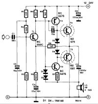
    Audio Amplifier on Transistors: Stereo Conversion, 2x17V Toroid Transformer & 2M Capacitor Marking

    1.It works for sure, and it's pretty good. Anyway, for some year it has been using a 4? loudspeaker

    2. I can describe the diagram. It comes from the "Elektor" magazine so there are no problems with the quality of the solution. Very stable. In total, the commissioning consists in checking the voltage on the emitters of the BD679 / 680 transistors

    3. Not many components, not bad parameters, for 80% I have a PCB design for it.

    4. I have made a simulation of the system, if it was needed or for reference.

    5. I recommend a solution
    6. If this arrangement will not fit, I suggest also one Link I also put it together and it sounded pretty good, I only changed the diodes from stabilization to transistor ;)

    Ps. I will not show a better diagram of the studio audio amplifier that we "tested" as a group in the studio because it is going to break down ...
    greetings
    EDIT:
    In the circuit from "Elektor" emitter resistors should be added (I added 1? ;)
  • #16 16822382
    aaanteka
    Level 42  
    [/url] The previous version of the amplifier from Elektor - even more simplified :) :

    Audio Amplifier on Transistors: Stereo Conversion, 2x17V Toroid Transformer & 2M Capacitor Marking

    - only four transistors in total.
  • #17 16822594
    398216 Usunięty
    Level 43  
    aaanteka wrote:
    follow the diagram "Eltron 100",
    Exactly; the same series also featured the Eltron 30 - the scheme is practically the same, the difference is two, not four, power transistors and a smaller power supply. At the same time, the amplifier is "idiot-proof" thanks to the use of a circuit that prevents excessive current flowing through the power transistors (eg in the event of an output short-circuit).
    https://obrazki.elektroda.pl/44_1209907625_thumb.jpg

Topic summary

The discussion revolves around the conversion of a mono amplifier schematic to a stereo configuration, utilizing a 2x17V toroidal transformer and addressing the marking of a 2M capacitor. Participants suggest modifications to improve the design, recommending the "Eltron 100" amplifier schematic with modern transistors like 2SC5200/2SA1943 or simpler Darlington pairs such as BDX53/54. Concerns are raised about quiescent current stabilization and the potential instability of the proposed design. Participants emphasize the necessity of duplicating the amplifier path for both channels while sharing various schematic examples and solutions, including a simplified version from "Elektor" magazine. The conversation highlights the importance of using discrete components and offers guidance on achieving a functional and stable amplifier suitable for educational purposes.
Summary generated by the language model.
ADVERTISEMENT