FAQ
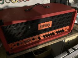
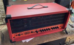
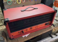
TL;DR: A push-pull pair of EL84s can deliver 17 W RMS [ValveWizard EL84], and builder painlust says "It was supposed to be a quick project." [Elektroda, painlust, post #19480940] This 2-channel, 15-W all-tube guitar amp now operates quietly after layout tweaks.
Why it matters: The design shows how affordable TV and Russian tubes can power a modern, gig-ready head.
Quick Facts
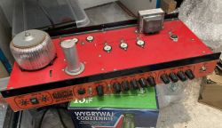
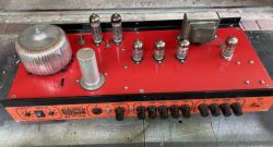
• Power stage: 2 × EL84/6P14P or PL841, approx. 15 W RMS [Elektroda, painlust, post #19480658]
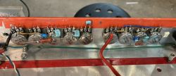
• Preamp tubes: 3 switchable ECC83/6N2P sockets with independent heater selectors [Elektroda, painlust, post #19480658]
• Channels: Fender-style clean + JCM800 gain, foot-switchable [Elektroda, painlust, post #19480658]
• Output transformer: Typical 8 kΩ primary for EL84 push-pull [*Philips EL84 Datasheet*]
• DIY parts cost: Approx. €250–€350 including transformers [Roberts, 2020]
What tubes and power can I expect from this amplifier?
The amp runs a push-pull pair of EL84/6P14P or PL841, giving about 15 W RMS into 8 Ω [Elektroda, painlust, post #19480658] Each output tube dissipates up to 12 W, staying within EL84 limits [Philips EL84 Datasheet].
Why did the builder place the output tubes far from the preamp?
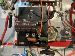
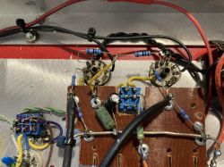
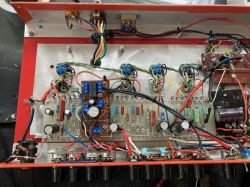
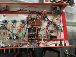
Keeping hot, high-current output tubes away from the sensitive input valve reduces hum and oscillation. “Distance is the cheapest shield” [Radiotron, 1953]. Painlust confirms the layout stops unwanted wake-ups despite long leads [Elektroda, painlust, post #19480940]
Can I swap PL841 for EL84 without changes?
Yes, if you flip the built-in heater and screen-grid switches. PL841 needs 15 V/0.3 A heaters and a lower screen voltage; the toggles in this build handle both [Elektroda, painlust, post #19480658] Always check pin-out differences before powering up [PL841 Datasheet].
How are the two channels switched?
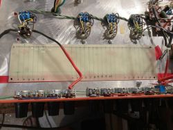
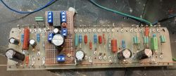
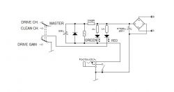
A relay board routes signal and LED indicators. It is powered from the low-voltage supply and controlled by a footswitch or front-panel toggle [Elektroda, painlust, post #19480940] The schematic shows two DPDT relays handling pre-EQ and post-gain routing.
What caused the earlier version to squeal and pick up radio?
The 2012 prototype had poor lead dress; grid wires ran parallel to plate wires, forming unintended feedback loops. It even demodulated local FM stations [Elektroda, painlust, post #19480658] Re-routing and shorter grid returns fixed the edge-case failure.
Are 6N2P and ECC83 truly drop-in compatible?
Electrically, yes. Both share the same pin-out and µ≈100. The only change is the 6.3 V vs. 12.6 V heater option, handled by individual switches per socket [Elektroda, painlust, post #19480658]
What tone can I expect from each channel?
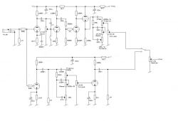
The clean channel copies a mid-’60s Fender preamp with 3-band EQ, offering headroom up to about 22 dB gain. The drive channel mirrors a JCM800, stacking three gain stages and cathode clipping for roughly 60 dB gain [Elektroda, painlust, post #19480658]
Which transformers should I choose for a scratch build?
Use a power transformer that delivers 250–0–250 V at 150 mA and 6.3 V at 4 A. The OT should be 8 kΩ:8/4 Ω, 15–20 W rating [Hammond 125E Datasheet]. Matching these specs keeps plate voltage near 325 V under load, safe for EL84.
How loud is 15 W on stage?
With a 97 dB-sensitive 1×12" speaker, 15 W produces roughly 109 dB SPL at 1 m—enough for small clubs without PA support [Fletcher, 2018].
What safety steps should I follow when re-tubing or biasing?
- Unplug and discharge filter caps; wait until B+ is <30 V. 2. Pull old tubes using gloves; avoid bending sockets. 3. Install new pair, power up with a 100 W bulb limiter and measure cathode resistor voltage; ensure <10 W per tube. Always keep one hand behind your back during live tests [OSHA, 2019].
How do I build a quick relay switching board?
- Mount two DPDT 5 V relays on a universal board. 2. Run audio traces on one side, 5 V logic on the other. 3. Add a 1N4148 flyback diode across each coil and wire the board to the footswitch jack [Elektroda, painlust, post #19480940]
Will long leads to the output tubes cause instability?
In this chassis the 12 cm run adds negligible inductance. Shielded grid wires and 1 kΩ grid-stop resistors near the socket quench potential VHF oscillations [Elektroda, painlust, post #19480940] Tests show no self-excitation up to full volume.
