logo elektroda
logo elektroda
X
logo elektroda

How do I integrate the Satel Integra 64 with INT-IORS to control lights and roller blinds?

wurban 17909 39
Best answers LABEL_AI_GENERATED

How can I wire a Satel Integra 64 with INT-IORS expanders so I can control individual lights and roller shutters manually and also force them into an alarm mode?

Use separate relay-controlled circuits: one output per lighting circuit and two outputs per roller shutter (up/down), because a shared relay setup only gives you all-on/all-off behavior and won’t let you control or override each load independently [#9767078][#9772638][#9783114] For the lights, the recommended approach is to connect each fitting or lighting circuit to its own Integra/INT-IORS relay output, with a bell/pushbutton switch as the local input and the Integra relay acting as the central control [#9772638][#9810821] For the shutters, use two outputs per blind so you can raise and lower them separately, and arrange the wiring so that the manual “open” signal is disconnected when “close” is commanded, and vice versa [#9767078][#9783114] If you want the alarm to take over, use the INT-IORS relay contacts in an NC/NO changeover arrangement so normal manual control works when the system is idle, and the automation/alarm path can switch the lights on and lower the shutters when needed [#9767308][#9771469] If the loads are split across several breakers, keep them on separate outputs and use an additional relay only as a higher-current interface if needed [#9764333][#9765428]
AI summary based on the discussion. May contain errors.
ADVERTISEMENT
Treść została przetłumaczona polish » english Zobacz oryginalną wersję tematu
  • Request for INT-IORS wiring diagram for lights and shutters

    #1 9763937
    wurban
    Level 9  
    Posts: 12
    Hello!
    I’ve moved this thread from the ‘Fixed Security Systems’ section because nobody there was willing to help me; I even received the reply: ‘It’s dead for free’.

    To get to the point, I have a question for the experts. I’d like to set up a home automation system based on the Satel Integra 64 and INT-IORS expanders. I must admit, I’ve never worked with these expanders before. I have a basic understanding of Satel and electrical engineering. The automation is intended to work as follows:

    5 lights connected to the expander, switched on and off via a wall switch and the keypad. When the alarm is triggered, I want all the lights to come on and remain on until (until) the alarm is cleared.

    Roller shutters 8. The same applies to the roller shutters: switching on/off via the keypad or the button by the window. When the alarm is triggered, all the roller shutters lower and cannot be raised until the alarm is cleared.

    There might be a few more lights as there are also garden lights, but that’s just a matter of buying additional expanders. The problem lies in the connection itself. I should be able to sort out the configuration.

    I’d be very grateful for a rough diagram showing how the connection between the roller shutters and the lights should look.

    Many thanks in advance.
    Wojciech Urbanowicz

    [retrofood]


    ............................................................
    mod:suworow
    You may also find this interesting:

    Satel Integra – system installation and configuration – selected topics


    Please feel free to explore our other guides, featured topics and articles on security systems :
    Fixed security systems. Alarm systems, CCTV cameras, intercoms, gate and roller shutter operators, home automation. Featured topics and guides.
    If you cannot find the answer to your question in the topics listed above, please visit our forum
    https://www.elektroda.pl/rtvforum/forum77.html


    I also encourage you to visit the General Guides section, where you’ll find resources from other sections of the forum, including those for beginners to electronics :
    https://www.elektroda.pl/rtvforum/forum510.html
  • ADVERTISEMENT
  • Load-rated relays parallel switching lights and blinds

    #2 9764333
    andszka
    Level 16  
    Posts: 177
    Help: 15
    Rate: 29
    In short – you need to connect in parallel to the circuits that switch on the lights and blinds
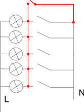
    using a relay controlled by the Integra’s outputs. Of course, you’ll need to know the current draw of the lights and roller blinds so that the relay closing these circuits is capable of handling such currents. Since you have some knowledge of electrical engineering and the Satel system, two outputs on the Integra – controlling two relays (one for the lights and the other for the roller shutters) – will practically suffice. However, the type of relays you choose will depend on the loads (i.e. their current requirements). I think that the type of relay and the protection used should go a long way towards helping you select the right relays.
  • #3 9765266
    wurban
    Level 9  
    Posts: 12
    As for the relay, I’ll be using an INT-IORS. It’s designed for 230V. Could someone perhaps draw me a simple diagram, as I can’t quite picture it? Something in Paint would be fine, for example.
  • #4 9765428
    andszka
    Level 16  
    Posts: 177
    Help: 15
    Rate: 29
    I don’t think the relay at the output will be able to cope with that. A schematic diagram is attached. The circuit and the relay contacts from the integrated circuit are marked in red. The same applies to the roller shutters.
    How do I integrate the Satel Integra 64 with INT-IORS to control lights and roller blinds?
  • Helpful post

    Separate outputs and interlocked shutter controls required

    #5 9767078
    pafciowaw
    Automation specialist
    Posts: 2439
    Help: 480
    Rate: 365
    Just my two cents... ;)
    With this sort of connection, the ‘manual’ system will only work for switching everything on or off at once. To do it properly: you need to connect each independent light fitting to a separate output on the head unit. The situation with the roller shutters is trickier: you must provide for the manual ‘open’ signal to be disconnected whilst simultaneously controlling the ‘close’ signal; the same applies when you want to send an ‘open’ signal from the head unit – in which case you must block or disconnect the manual ‘close’ signal.
  • Helpful post

    Cascaded relays and NC contacts control lights and blinds

    #6 9767308
    acid12
    Level 21  
    Posts: 388
    Help: 41
    Rate: 23
    The lighting can easily be controlled using one output from the integrated circuit; you can use a relay that triggers subsequent relays in a cascade (each one dedicated to a separate lighting circuit to prevent short circuits between them).

    You could do the same for the roller shutters, too – use two main relays (open/close) to trigger subsequent ones (just as with the lighting) – but, as pafciowaw mentioned, you need to take into account the opposite signals from the manual control; they can be connected to the normally closed (NC) contacts of the control relay, so that power reaches the manual switch only when the control relay from the head unit is not activated.
  • Helpful post

    Adding eight outputs enables individual lighting and shutter control

    #7 9768035
    pafciowaw
    Automation specialist
    Posts: 2439
    Help: 480
    Rate: 365
    Of course – you can use a single output on the control unit to handle an ‘ALARM’ scenario (closing the roller shutters and switching on the lights throughout the house and garden) by configuring the appropriate set of relays to duplicate the control signal (a sufficiently large number of NO contacts to power the lighting/roller shutters and NC contacts to disconnect ‘manual’ signals, but…
    Since the client is using the integration system for control and alarm functions, it practically begs for specific light fittings, roller shutters and other ‘extras’ to separate outputs so that, in future, one can make use of lighting scenes or simulations of occupants’ presence; the ability to switch off any lighting points that have been accidentally left on (and switched on manually) the moment you leave the house and arm the alarm – for safety and to save energy.
    Adding a further 8 outputs costs around 300 PLN, but this gives us the above-mentioned capabilities for individually controlling electrical loads.
  • ADVERTISEMENT
  • Request for INT-IORS wiring and switch isolation diagram

    #8 9771376
    wurban
    Level 9  
    Posts: 12
    Hello! Cost is not an issue. Well, of course there are some limits, but I was thinking I’d at least add three INT-IORS expanders. I reckon this solves the issue of using separate relays. I want to have about eight lighting outputs and eight for the blinds, all separate. Everything separately. That’s exactly what I had in mind when thinking about user simulation and so on. I also like the idea of switching off lights that are already on. I’m considering automated windows, but that’s more of a long-term prospect. I also want to set it up so that, in the event of an alarm, the entire property is secured – meaning that if the gate were open, it would close during an alarm, and the same would apply to the driveway. I’m planning to use motorised drives for the gate and the driveway.

    If I were to use INT-iORS, how would I connect it so that, as I mentioned, the wall-mounted switch is disabled? I know that the Integra system offers a huge range of possibilities and I’d like to make the most of them.

    I’ll probably get an installer to help, but I’d like to know how to do it so I can try and do it myself.
    If anyone has a moment, I’d appreciate a simple diagram and description.
  • Helpful post

    Using INT-IORS NC/NO outputs for manual and alarm control

    #9 9771469
    acid12
    Level 21  
    Posts: 388
    Help: 41
    Rate: 23
    Well, if the cost of the expanders isn’t an issue, then all the more reason to use separate outputs.
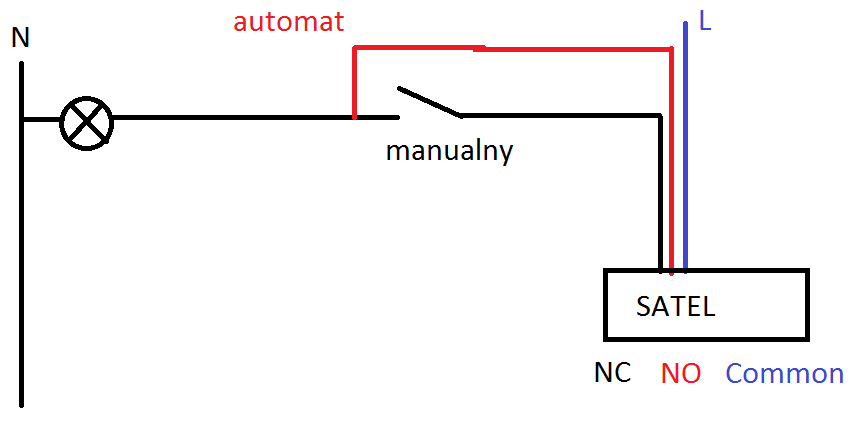
    In the INT_iORS module, you have both NC and NO outputs; you connect a standard ‘manual’ circuit to the NC (normally closed) output, and run a parallel connection from the NO (normally open) output.

    How do I integrate the Satel Integra 64 with INT-IORS to control lights and roller blinds?

    When the system is operating normally, power is supplied by SATEL to the NC terminal -> for manual control
    When the system is in alarm mode, power is supplied to the NO terminal -> the circuit is short-circuited and the lights come on (the shutters close, etc.)
  • Helpful post
    #10 9772467
    pafciowaw
    Automation specialist
    Posts: 2439
    Help: 480
    Rate: 365
    With this wiring diagram, it will not be possible to switch off a light that has been switched on manually -(
  • Question about two outputs per separately controlled blind

    #11 9772523
    wurban
    Level 9  
    Posts: 12
    Thanks, acid12, that’s helped me a bit. But as pafciowaw said, there’s no way to turn off the display. If you can, pafciowaw, could you send me your idea in graphic form?

    I’m still thinking about the blinds. I want the system to raise and lower them. So will I need to use two outputs for each blind? Because, as I said, I want everything to be controlled separately.

    I’d be happy with sketches, even in Paint.
  • ADVERTISEMENT
  • Helpful post

    Integra relay scheme provides manual lighting fallback control

    #12 9772638
    pafciowaw
    Automation specialist
    Posts: 2439
    Help: 480
    Rate: 365
    How do I integrate the Satel Integra 64 with INT-IORS to control lights and roller blinds?
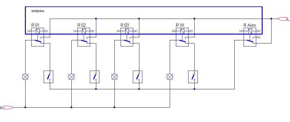
    The Integra outputs R 01, R 02, …, R XX are direct connections to each light fitting;
    The R Auto output is used when Integra takes over control of the lighting.
    The Auto output may (should be) duplicated by a relay with more robust contacts and with enough contacts to handle the lighting circuits in the cottage (I assume there are several lighting circuits/several ‘S’-type fuses)
    Advantages of this control method?:
    When the Integra is not powered or not in operation – the relays are in the off state as shown in the diagram – it is possible to switch the lighting on and off just as in conventional systems.
    Once a command is sent from the Integra R Auto, it is possible to switch on (and off) any light fitting.
  • #13 9773371
    wurban
    Level 9  
    Posts: 12
    Hello! It’s a really nice circuit, but I’d have to duplicate the ‘auto’ input as many times as there are lamp terminals. So I think I’ll use everything you’ve outlined, just without the ‘auto’ resistor.

    As for the blinds, how should I go about this? Do I need to use two outputs? 1 – ‘up’, 2 – ‘down’?
  • #14 9783114
    pafciowaw
    Automation specialist
    Posts: 2439
    Help: 480
    Rate: 365
    How do I integrate the Satel Integra 64 with INT-IORS to control lights and roller blinds?
    Hello
    The R Auto output should be used to get the most out of the system (in ‘auto’ mode, you can switch any light fitting or blind on and off)
    Regarding blinds:
    Using two outputs from the control unit allows you to close and open any blind.
    To control the blinds when an alarm is triggered, all you need is a relay to lower them. Once the alarm has cleared, the blinds will remain closed but manual control will become available (according to the initial assumptions in the post).
    Best regards, and I hope you find this food for thought.
  • #15 9784701
    EMEA Gateway
    Level 12  
    Posts: 41
    Mate,
    It’s clear you’re getting more and more interested in smart homes. You’ll soon start thinking about monitoring and control. When it comes to home automation, there are so many things to monitor – temperature, humidity, utility consumption, sunlight, wind... there can be a great many. I suggest you take a look at a very interesting controller which meets the highest standards for this type of system, and what’s more, you can easily control your home using it via the Internet, an iPod, an iPad, an iPhone… etc. The structure of such a system is available at http://emeagateway.eu/emea/pl/cat/239; you’ll find the controllers at http://emeagateway.eu/emea/pl/cat/198, and descriptions of the necessary components throughout the http://emeagateway.eu portal.
  • #16 9800808
    wurban
    Level 9  
    Posts: 12
    Hello!
    As for the measurements and so on, I don’t think I’ll be going for that level of automation, due to the costs, the pneumatics, the furnace controller, and so on.

    I need to think through the automatic output and discuss it with the client, as the lighting alone will require two circuit breakers, not to mention the garden and the roller blinds.
    Still, I like the diagrams – they’re very clear and easy to follow.

    The automatic output is such a headache for me because I need to have everything on separate circuit breakers. I can’t have everything lumped together.
  • #17 9810176
    wurban
    Level 9  
    Posts: 12
    Hello!
    I was just wondering whether it’s possible to set something up so that, for example, when I walk into the house, the lights in the hallway and living room come on, and I can switch them off manually. Something like a staircase light switch.

    However, at the same time, I’d like to be able to manually lock the lights during an alarm, as I mentioned. I suspect this will require more expanders, but the client is willing to cover the extra costs. If this is possible, could you please send me a diagram so I can see if I can get to grips with it?
  • #18 9810821
    pafciowaw
    Automation specialist
    Posts: 2439
    Help: 480
    Rate: 365
    When it comes to ‘automatic’ lighting in selected rooms and, for example, the timed switching on of others, it would be advisable to review the concept from the outset and use:
    Integra as the switching/main/alarm system;
    Monostable light switches (the ‘doorbell’ type) connected to Integra’s inputs;
    Lighting points connected individually via Integra relays.
    With such connections and configurations, it is possible to adjust the programme’s operation in such a way as to meet the requirements discussed in the post.
  • #19 9811555
    abber
    Level 11  
    Posts: 76
    Help: 1
    Rate: 2
    Hello everyone, like wurban, I want to automate my new house. I’m thinking along the same lines as you – every light, every blind, and so on. I’m also thinking about having the air conditioning controlled by the home automation system.
  • Configuring output 17 for lighting and alarm activation

    #20 9832601
    wurban
    Level 9  
    Posts: 12
    Hello!
    Right, I understand the whole thing. I know how to connect it and so on, as I’ve already drawn up a diagram; I like the solution with the bell switch. It’s just a question of how to programme it now. The problem is that I don’t know what type of reaction to set for, say, input 17 so that output 17 is triggered. For the output, it seems to me that it needs to be an ‘input violation’ reaction, and I’ve specified input 17. But I’m not sure what to do next. After all, it’s also supposed to trigger during an alarm. I’m not really sure what to do. I’ll set up the roller shutters as shown in the diagrams above, but for the light I’d like to do it as I mentioned earlier.

    Could someone send me a configuration, even just for one output and one input, when they have a spare moment, so I can get a rough idea? But with a configuration where, for example, output 17 is activated during an alarm, and the lighting is switched on when the system is in standby mode.

    Or do I simply need to use another output on the INT-IORS?
  • #21 9915556
    dudu82
    Level 11  
    Posts: 41
    Rate: 11
    Hello.

    I have a similar problem, in that I want to control several light fittings from a single output. And I’m having trouble with the ‘returning’ phase. I’ve wired it from the control unit so that the phase from a single output goes to the switch (on the load side) in the rooms where the lights are to be switched on.
    But when I have two rooms connected to a single relay output, the moment I switch on the light in one of those rooms using the wall-mounted switch, the light in the other room also comes on. The live simply loops back via the power cable from the Integra. I’ve tried using some diodes, but either the shop gave me the wrong ones or there’s something wrong with them, because they conduct in both directions.

    Do you have any tried-and-tested methods for blocking the live wire in a 230V circuit so that it only flows in one direction?


    Oh, and one more thing: I’ve programmed the outputs in Int-Ors, but it doesn’t seem to be working. I’ve ticked the ‘polarity’ option. So, in theory, the output isn’t inverted. If I deselect ‘polarity’, all the outputs switch on even though the conditions for the sums and products of the other outputs on which they depend aren’t met (and I suppose that’s the correct behaviour, as the outputs are then inverted). Despite the settings being correct (I think), the virtual inputs controlling these physical outputs do not ‘work’ even though the conditions set for them are met. What could I be doing wrong, as I assume it’s my fault?
  • #22 9915614
    acid12
    Level 21  
    Posts: 388
    Help: 41
    Rate: 23
    Connect a relay with two parallel outputs to the output of the integrated circuit; it will switch both on, but the circuits will be separate from one another
  • #23 9917240
    dudu82
    Level 11  
    Posts: 41
    Rate: 11
    That’s a good idea. But I’d have to fit those relays behind the switch. I do have deeper junction boxes, but there are still quite a lot of wires in there because I’ve made the connections inside them (I don’t have those large junction boxes up near the ceiling).
  • #24 9918144
    acid12
    Level 21  
    Posts: 388
    Help: 41
    Rate: 23
    Otherwise, you won’t be able to block the phases – i.e. with alternating current, it always ‘flows in both directions’; a diode won’t help here. You could perhaps use electronic relays, or even triacs; the important thing is that the phases of the two circuits are physically separated from one another.
  • #25 9921152
    dudu82
    Level 11  
    Posts: 41
    Rate: 11
    Right. I think I’ll go with these relays, as I can’t find a 230V voltage-controlled triac.
  • #26 10040886
    elmłot
    Level 18  
    Posts: 361
    Help: 13
    Rate: 19
    The interior lights come on when the OKI alarm is triggered, but the blinds are raised at that point.
    If someone disables the audible alarms, they can go about their business undisturbed with the blinds drawn and the interior lit up.
  • Limit lights and shutters to verified emergency alarms

    #27 10041739
    Anonymous
    Anonymous  
  • ADVERTISEMENT
  • Using roller shutter sensors for alarm and lighting automation

    #28 10041941
    elmłot
    Level 18  
    Posts: 361
    Help: 13
    Rate: 19
    Sabotage does not raise the roller shutters!!!
    But are these roller shutters burglar-proof???

    Returning to the discussion rather than a squabble, when using roller shutters, it is recommended to install reed switches or roller shutter sensors (the CA64-E expander with software version 2.0 and the Integra with software version 1.6 or higher can be connected to roller shutter sensors). This protects the roller shutters from damage. Setting the roller shutters to the ‘closed’ position so that they can be easily raised by 10–15 cm encourages someone to lift them, and at the same time triggers an alarm and a notification, etc. These sensors are located in a zone that does not activate the ‘raise roller shutters’ function!
    The ‘raise roller shutters’ function is activated by an alarm in the zone where the sensors are located inside the building – these sensors will also switch on the lights.
    Turning the lights on for a specific duration could also be triggered by a zone containing roller shutter sensors or reed switches. Raising the shutters by a few cm turns the lights on for 1–5 minutes and triggers the alarm.

    Visitors specialising in roller shutters (standard ones – not anti-burglary types) have just suggested to me that triggering the alarm should raise the roller shutters rather than lower them; depending on the property, this can be viewed in different ways, but sometimes it’s a very good solution, whilst at other times it doesn’t make much difference (no neighbours)

    Added after 11 [minutes]:

    It’s also worth considering that in summer you can open the windows and lower the blinds (roller blinds) to allow for micro-ventilation, and activate the ‘roller blind’ zone. In such cases, switching on the lights may be desirable or undesirable for the owner. One could add another virtual input to control the lighting: the lights will not switch on if only the ‘roller shutter’ zone is active.
    There are many other options available.
  • #29 10042153
    Anonymous
    Anonymous  
  • #30 10042715
    elmłot
    Level 18  
    Posts: 361
    Help: 13
    Rate: 19
    Lad, give yourself a tap on the forehead.
    Unfortunately, there are more and more teenagers on this forum looking for a row.

    I’m telling you quite clearly that the ‘raise the shutters’ option is triggered when an alarm is verified in the zone! The zone covers the detectors inside the building, so if someone enters the building, the shutters will go up.
    You can set up a zone containing roller shutter sensors or reed switches, and this zone won’t raise the shutters but will trigger an alarm. Similarly, a tamper event won’t raise the shutters but will trigger an alarm.

    Read up on how to programme the control panel before you start handing out prizes.
    Once you’ve learnt what the ‘Sabotage’ function is for, you’ll understand how the roller shutter raising mechanism I’m describing works.
ADVERTISEMENT