logo elektroda
logo elektroda
X
logo elektroda

Creative A220 Speakers Mini-Din 9-Pin Plug Replacement: Diagram and Soldering Guide

flupp321 38048 20
ADVERTISEMENT
Treść została przetłumaczona polish » english Zobacz oryginalną wersję tematu
  • #1 9800424
    flupp321
    Level 2  
    Hello
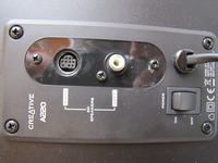
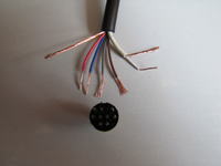
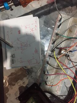
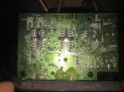
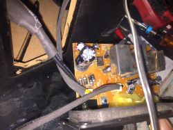
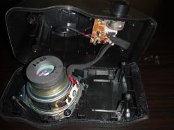
    I have such a problem that the previous plug broke from the speakers and unfortunately I could not see the diagram because it was flooded ... I bought a new plug and I would like to solder it myself and I would like to have a diagram as to what to solder ... I am sending photos. If we need more photos, I will send new speakers for help and two experts could not fix it .. thanks
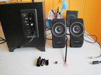
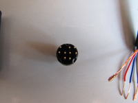
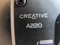
    Creative A220 Speakers Mini-Din 9-Pin Plug Replacement: Diagram and Soldering Guide Creative A220 Speakers Mini-Din 9-Pin Plug Replacement: Diagram and Soldering Guide Creative A220 Speakers Mini-Din 9-Pin Plug Replacement: Diagram and Soldering Guide
    Creative A220 Speakers Mini-Din 9-Pin Plug Replacement: Diagram and Soldering Guide Creative A220 Speakers Mini-Din 9-Pin Plug Replacement: Diagram and Soldering Guide
  • ADVERTISEMENT
  • #3 9800881
    Sanowiak20
    Level 21  
    You have to carefully cut the old plug because there are surely pieces of wires left, then just ring the meter and the problem is solved.
  • #4 9801264
    flupp321
    Level 2  
    I cut it and you can't see anything; / Do you have other ideas?
  • #5 9801427
    Sanowiak20
    Level 21  
    In that case, there is hope that someone will start their equipment for you and take measurements.
  • #6 9801543
    flupp321
    Level 2  
    I also have Creative working, but I'm afraid to cut open, because if I don't fix it, 2 sets will be thrown away ... Mother-in-law A220 and I have A320, it's rather the same ...
  • #7 9801580
    Sanowiak20
    Level 21  
    It is enough to unscrew the satellite with the control and you can see the wires there.
    Then check with a meter which color to which pin.
  • ADVERTISEMENT
  • #8 9802755
    gradek83
    Level 42  
    Creative A220 Speakers Mini-Din 9-Pin Plug Replacement: Diagram and Soldering Guide
    7 RED
    8 GRAY
    9 WHITE
    3 BLUE
    4 NC
    5-1 BROWN
    6 NC
    2 COPPER
    MASS (HOUSING) COPPER
  • #9 10075319
    thechef
    Level 2  
    Hello everyone, I have a problem with my Creative 2.1 speakers, but in my case the remote control has mini jack ends on both sides, of course, the connection is interrupted by me, but it's not the plug's fault, but the entire cable, I took this remote apart and I want to replace the cables with new ones, but I can't find one somewhere connectors which connect the cables with the board
    I am giving a picture of something white but for 6 cables where will I buy it and how do I clamp the cables in it?
    http://www.conrad.pl/Z%b3%b1czka-do-p%b3ytki-...le7=conrad?=743151&ci=SHOP_AREA_17376_0224410
    sooner something like this
    http://sklep.monster.pl/LH-06-GNIAZDO-6-PIN%284,36253,26695%29.aspx
    I don't know :(

    help !!
  • #10 10101278
    Bogdan200012
    Level 11  
    It stops when you turn the knob or when you move the cables?
  • ADVERTISEMENT
  • #11 10104425
    thechef
    Level 2  
    the cable because the mini jack is new, the electrician did it to me
  • #12 10104609
    Bogdan200012
    Level 11  
    What do you need a coupler for?
    You solder directly to the pilot board.
  • #13 10108427
    thechef
    Level 2  
    I want to renew the cables with this remote control, they are almost 10 years old. I will not solder to the board because it is, only the plug for this I have to buy and insert new 6 din cables and I ask what are these clamping cables?
  • #14 10108737
    gradek83
    Level 42  
    Cut the cables somewhere 5 cm in front of the plug, buy a heat shrinkable band, galvanize the wires and solder new cables.
  • #15 10112632
    thechef
    Level 2  
    I did as you said, only there is a problem with the sound, if I turn up a little, they are already playing loud and if I would give it full blast, it would tear the sub speakers at the minimum and rumble. I remember that I had it when I connected directly with a cable without a remote control, it was also like that, and one more thing, when it is completely muted, it rumbles so, hums in the speakers I do not know what is going on, there is maybe some possibility to bypass this remote because in a month I am buying a sound card and monitors krk rokit 5 I wanted to connect it all together so that I could make it loud with one knob?
  • #16 14876853
    malarz128
    Level 12  
    5 + 1 blue shouldn't be gray sometimes?
    3 blue
  • ADVERTISEMENT
  • #17 15850637
    ManiekM80
    Level 9  
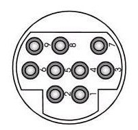
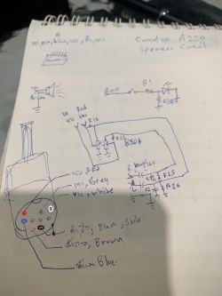
    Pin-out of mini DIN 9 Creative A220 plug.
    It is true that it is already above, but it probably won't hurt in this version:

    Creative A220 Speakers Mini-Din 9-Pin Plug Replacement: Diagram and Soldering Guide
  • #18 20416401
    charandb
    Level 2  
    Creative A220 Speakers Mini-Din 9-Pin Plug Replacement: Diagram and Soldering Guide Creative A220 Speakers Mini-Din 9-Pin Plug Replacement: Diagram and Soldering Guide Creative A220 Speakers Mini-Din 9-Pin Plug Replacement: Diagram and Soldering Guide

    ผมได้ถอดเครื่องมาวัดขาว่าขาไหนเป็นอะไรบ้าง แต่ฉันไม่มีตัวตู้ลำโพงที่มีปุ่มเปิดปิดและปรับเสียง หากคุณถ่ายรูปให้ฉันดูวงจรทั้ง 2 ด้าน ฉันจะบอกมันให้
    I have taken off the machine to measure the leg which leg is what. But I don't have a speaker box with power and volume buttons. If you take a picture for me to show both sides of the circuit, I'll tell you.
  • #20 20428296
    charandb
    Level 2  
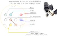
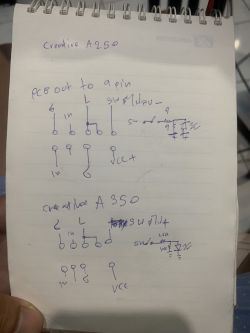
    Connect the cable as shown below. Please be careful to connect the wrong cable in the picture, which is the front.
    Creative A220 Speakers Mini-Din 9-Pin Plug Replacement: Diagram and Soldering Guide

    for other models
    Creative A220 Speakers Mini-Din 9-Pin Plug Replacement: Diagram and Soldering Guide

Topic summary

The discussion addresses the replacement and soldering of a broken Mini-DIN 9-pin plug on Creative A220 speakers. The original wiring diagram was lost due to water damage, complicating repair efforts. Suggestions include carefully cutting the old plug to expose wire ends and using a multimeter to identify wire-to-pin connections. Unscrewing the satellite speaker with the control unit allows access to internal wiring for verification. A pinout was provided: pin 7 (red), pin 8 (gray), pin 9 (white), pin 3 (blue), pins 5 and 1 (brown), pin 2 (copper), with the housing as ground (copper). Additional photos of the speaker board with potentiometer and wiring diagrams were shared to assist soldering. Some users discussed related issues with Creative 2.1 speaker remotes and cable replacements, emphasizing direct soldering to the board or using heat shrink tubing after cutting cables. The conversation also touched on troubleshooting sound issues such as excessive volume and humming, and the possibility of bypassing the remote control. Links to related forum threads and images of pinouts for similar models (T3100, SBS380, A320) were provided for reference.
Summary generated by the language model.
ADVERTISEMENT