logo elektroda
logo elektroda
X
logo elektroda

4kW generator with neodymium magnets for vertical power plant.

darklon 67317 13
ADVERTISEMENT
Treść została przetłumaczona polish » english Zobacz oryginalną wersję tematu
  • #1 10461330
    darklon
    Level 10  
    Hello and welcome. Would you like to take a look at this video where the gentlemen allegedly built a 4kW generator based on neodymium magnets?
    Can you actually get power performance on it?
    here is the video:
    http://www.youtube.com/watch?v=5D_lJka2wDg&feature=related

    It seems to me that the turbine will not be able to achieve this, in the video the gentlemen obtained about 500 watts from this hand spinning.
    I'd like to build a prototype of something like this. is it worth it?
  • ADVERTISEMENT
  • #2 10461674
    INTOUCH
    Level 30  
    A prototype is worth it, but you won't do it without the basics and knowledge of the theory.
  • ADVERTISEMENT
  • #4 10462150
    darklon
    Level 10  
    I know theories, I study a related field.
    It's more about practical advice. Is it worth it or is it better to buy a generator.
    I do not know what the quality of this energy will be and whether this solution of the windmill itself (screw) will be appropriate.
    The cost of one such magnet is probably about PLN 50, so it will not be that cheap.
  • #5 10462315
    JESIOTR1
    Level 33  
    darklon wrote:
    It seems to me that the turbine will not be able to achieve this, in the video the gentlemen obtained about 500 watts from this hand spinning.
    I'd like to build a prototype of something like this. is it worth it?

    The gentlemen together achieved 500 W, of which the light bulb consumed about 100 W, and the remaining 400 W power in their hands was used in the winding of the generator and turned into heat.
    The construction is energy-intensive in general - it is wasted in the generator.
    The main disadvantage is the waste of space in the jet gap between the discs.
    The length of the wire in the winding is long and easily induces over 500 V, but it has a large resistance (judging by the volume of the coils and the thickness of the wire) and it is in these coils that the energy is wasted P = I? (circuit current) x R (coil resistance).
    These coils have more resistance than this bulb - I'm estimating 4:1, that divides the 500 watts of those hands into 400 watts in the windings and 100 watts in the bulb. An idling sander needs less power than a bulb.
    The shape of the coils, the shape of neodymium (very small active section) and many avalanche errors.
    They overdid the proportions - it would be best if 4 such bulbs were connected in SERIES to the film show, so that they would have a rated voltage of the receiver of about 1000 V, they would have to spin twice as fast, but they could apply 4 times less force.
    Gentlemen spin well but do not understand any of the laws of Physics.
  • ADVERTISEMENT
  • #6 12993574
    Edek1313
    Level 9  
    JESIOTR1 wrote:
    darklon wrote:
    It seems to me that the turbine will not be able to achieve this, in the video the gentlemen obtained about 500 watts from this hand spinning.
    I'd like to build a prototype of something like this. is it worth it?


    Gentlemen spin well but do not understand any of the laws of Physics.


    Sturgeon, I am also starting to build a neodymium magnet generator. Do you know or does anyone know a website where the parameters of the magnets used are given - dimensions and detailed construction of a single coil described with parameters?

    I understand that it is better to convert a motor into a generator than to build the so-called "American". I care about revolutions from 200 to 400, one or two phases, power about 4 - 8 kW. The generator would be powered by a water wheel, so "unreliable" windmills are not an option.

    I also understand that achieving a full sine wave and "using" it in practice, not only for emergency power supply in the whole house, is no longer a problem? For example, most UPSs have full sine waves and less and less simulated ones. I think I could do something like this myself, but it's the most optimal thing for me. I have workshop facilities, a few old washing machine motors, squirrel-cage motors and many others, "smaller - larger", where I could use them for this purpose.

    I've read a lot and every magpie ... praises its tail. I don't want to waste time on unnecessary constructions. I found a lot of companies that produce professional generators, but I can't afford them financially. I mean pointing to a link or advise where I could find the most optimal design for me.

    Look at the first position, these prices are prohibitive for me. The rest I implement and use in order to draw appropriate, practical conclusions:

    http://www.genervolt.pl/products.html

    http://www.mala-elektrownia.ovh.org/pradnica.php

    http://www.newimiue.ipnet.pl/dokumenty/E16.pdf

    ... and many, many more, most of which have probably already been.
  • #7 13019680
    JESIOTR1
    Level 33  
    Edek1313 wrote:
    These prices are prohibitive to me.

    Unfortunately, the basic parameter of neodymium and coils is their price.
    For your needs (rotation and power = materials) the rotor must cost over PLN 1000 and the stator the same.
    4kW generator with neodymium magnets for vertical power plant. 4kW generator with neodymium magnets for vertical power plant. 4kW generator with neodymium magnets for vertical power plant.
    In addition, professional labor - prices in the first position are not excessive.
    For the water wheel, all you need is a generator from the washing machine engine + gear.
    You will get 200-400 V and up to 10 A. You need to select a receiver for 1 kW and replace the bearings from time to time.
    A slow-speed without a gear has the right to be more expensive.
  • #8 13030184
    Edek1313
    Level 9  
    JESIOTR1 wrote:
    Edek1313 wrote:
    These prices are prohibitive to me.

    Unfortunately, the basic parameter of neodymium and coils is their price.
    For your needs (rotation and power = materials) the rotor must cost over PLN 1000 and the stator the same.

    In addition, professional labor - prices in the first position are not excessive.
    For the water wheel, all you need is a generator from the washing machine engine + gear.
    You will get 200-400 V and up to 10 A. You need to select a receiver for 1 kW and replace the bearings from time to time.
    A slow-speed without a gear has the right to be more expensive.


    You answered very comprehensively, thanks :D

    It occurred to me that I could choose a motor, i.e. buy a new one, with the coils already optimally used there, for the generator, i.e. shape, cross-section, etc., and convert only the rotor itself into a generator.

    I have access to lathes, milling machines and "support" in this area. I thought about milling the longitudinal grooves and walls at an angle deeper in the rotor - meeting at the top and the same matching of neodymium magnets, i.e. also milled so that they enter only from the front or back and thus stay inside.
    The whole thing would be mounted on some assembly glue - automotive, temperature resistant.

    I was just reading about the construction of electric motors and I tried to catch the difference in the construction and parameters of the coils and thus can choose a motor in this respect - as I wrote above.
    Such a solution would shorten the assembly time a bit.

    One more issue. I understand that the surface of the magnets should be maximally large, matched to the internal shape of the coil?
    I also want the losses to be as small as possible.
  • #9 13030708
    JESIOTR1
    Level 33  
    Edek1313 wrote:
    I could choose a motor, i.e. buy a new one, with the coils already optimally used there, for the generator, i.e. shape, cross-section, etc., and convert only the rotor itself into a generator.

    There are many motors with small rpm - it's not worth modifying them - it's enough to make an additional rotor with neodymium.
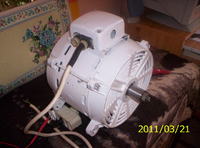
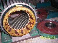
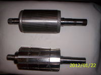
    We will then get as in the picture:
    ASYNCHRONOUS generator - 500 rpm (fixed to the mains), ASYNCHRONOUS engine - 470 rpm and slow-running SYNCHRONOUS generator - Three in one .
    4kW generator with neodymium magnets for vertical power plant. 4kW generator with neodymium magnets for vertical power plant. .
    The synchronous generator (after replacing the rotor) will have more than 3 times the power of the asynchronous generator with a full-time rotor).
    Sculpting rotors for neodymium is harmful - just stick it well.
  • ADVERTISEMENT
  • #10 13048835
    Edek1313
    Level 9  
    JESIOTR1 wrote:

    There are many motors with small rpm - it's not worth modifying them - it's enough to make an additional rotor with neodymium.

    The synchronous generator (after replacing the rotor) will have more than 3 times the power of the asynchronous generator with a full-time rotor).
    Sculpting rotors for neodymium is harmful - just stick it well.


    I already have my eyes on matches and I agree with you that in this case, it is probably the most optimal solution.

    Details remain:

    1. Hardly anyone returns and it does not mention that the shape of the magnets should match the internal shape of the coil - unless I am wrong about this.

    2. I haven't seen the photo or article, where someone would use magnets with an oval surface and thus obtain smaller distances between the coil and the magnet itself:
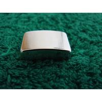
    4kW generator with neodymium magnets for vertical power plant.

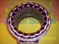
    Such information is provided, for example, by the creator of the generator from the university of technology - probably in Lublin. I'll post it when I find the PDF spec sheet. Anyway, it looks very professional like this:
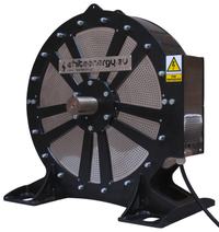
    4kW generator with neodymium magnets for vertical power plant.

    He wrote that the most optimal solution is the shortest possible distance between the coils and the magnets. These generators come in two versions, 1.5 kW and approx. 10 kW. I may have gotten a little confused about the exact values, but overall I gave the correct values.

    Returning to the issue of the internal shape of the coil, it seems to me that the magnet should be at least as large as the internal dimension of the coil. Such a solution allows for easier excitation of electron motion.


    3. Technical issues for general magnet attachment.

    I was thinking about the possibility of, for example, welding magnets - although it is known that this will not work, but, for example, gluing them to the rotor and putting a thin sheet metal cylinder on the rotor - it could be heated to expand it.

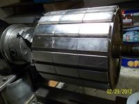
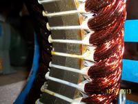
    I would just like to protect the magnets from crumbling, as you can see in your photo.
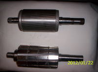
    4kW generator with neodymium magnets for vertical power plant.

    In general, I'm just trying to get the maximum possible distance and at the same time make a durable rotor.

    4. I forgot yet
    write about one thing. Namely, it's about the mostoptimal distances " side " between the magnets glued to the rotor. Considering pt. 1 , it seems to me that by placing them more densely, e.g. with a 5 mm gap, greater efficiency of such a generator will be obtained.

    I deliberately avoid references to formulas, conversions and calculations in order to focus more on general and basic issues.
    Once I've sorted it out, these elementary issues, then I'll delve into the details - though without exaggeration :)
  • #11 13057174
    JESIOTR1
    Level 33  
    Hello

    ad1. The coil must be beautiful without Cosine then - only flux lines that are perpendicular to the wire count - only the active section (frame) not to the coil.
    4kW generator with neodymium magnets for vertical power plant.

    ad2, The generator from the university is a scientific aid for exposing the laws of physics - the electric machine uses the laws of physics and has a better design.
    Copper must always be as close to the flux as possible.
    The shape of the coil has nothing to do with the shape of the magnet - it is the relative position of the pole axes (coil and magnet pair) that affects induction. The coil is two frames.

    ad3. You write about "imposing a thin sheet metal cylinder on the rotor - when applying it, it could be heated to expand". - even a short-term temperature above 80 degrees will destroy the magnetism in neodymium.
    In my photo the magnets are not crushed - the nickel coating is removed there so that it does not pretend to be strong.
    I sometimes removed 100% nickel from neodymium so that they would stick better and that after painting with resin they would be more durable than in nickel.
    TO REMOVE NICKEL it is enough to dent the coating by several movements, it will stick out and come off like butter.

    od4.optimal "lateral" distances = less than 1/3 of the pole width with classic three-phase.
  • #12 17867071
    Pioter-
    Level 12  
    Can I ask for this PDF if you already found it?
  • #13 19849869
    robertrosman
    Level 1  
    Has there been any progress on the subject? Maybe a summary. Like for example pdf
  • #14 19969515
    smootny

    Level 18  
    Anything on the subject has started - I'm also interested in it.

Topic summary

The discussion revolves around the feasibility of building a 4kW generator using neodymium magnets for a vertical power plant. Users express skepticism about the power output demonstrated in a referenced video, where only 500 watts were achieved through manual spinning. Practical advice is sought regarding the construction of a prototype versus purchasing a generator. Participants highlight the importance of understanding the theoretical and practical aspects of generator design, including coil resistance, energy efficiency, and the optimal configuration of magnets and coils. Suggestions include converting existing motors into generators and utilizing water wheels for power generation. The cost of neodymium magnets and the complexity of achieving efficient energy conversion are also discussed, with emphasis on the need for precise engineering to minimize energy loss.
Summary generated by the language model.
ADVERTISEMENT