logo elektroda
logo elektroda
X
logo elektroda

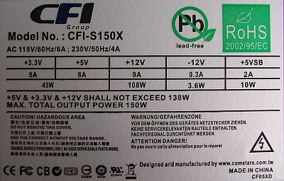
CFI Grup CFI-S150X Model: Irregular Voltage Fluctuations on 5VSTB Pin - Possible Causes?

ZbeeGin 21641 11
ADVERTISEMENT
Treść została przetłumaczona polish » english Zobacz oryginalną wersję tematu
  • #1 10821478
    ZbeeGin
    Level 39  
    CFI Grup CFI-S150X Model: Irregular Voltage Fluctuations on 5VSTB Pin - Possible Causes?
    Hello.

    The history of this power supply is somewhat complicated, and the fault seems to be simple.

    I worked yesterday on the computer until quite late. The computer worked for 4-5 hours without a break (usually this is its daily working time). Around 22:00 I turned it off, but after switching it off I noticed the keyboard lights going out every few seconds. Thinking that this is a problem with closing the system, I turned on the computer again. However, it required a slightly longer holding of the switch - which was no longer a normal symptom. I turned it off by holding the 4 sec. Switch. I disconnected the power supply completely from the mains until the morning.

    This morning, once again, the same symptom appears again. The voltage measurement on the 5VSTB pin has shown that the voltage disappears every few seconds. The power supply has been removed. The first thing is to check whether the electrolytic capacitor on the PP output has accidentally dried up. Optically it looked OK, but it was replaced with a new 1000?F / 10V (of course LowESR ). Unfortunately, this has not eliminated the vulnerability. Measurements of a few key PP elements would not show that they were damaged. I mentioned it prophylactically yet 10?F / 50V and 22?F / 50V on its original side.

    The power supply continues to "sample" on the 5VSTB line and can not be switched on the artificial load. There is also an additional symptom that was noticed during the measurements. When the voltage behind the bridge is "normal", ie 285V, the PP converter samples, but when the power supply is disconnected from the mains and the voltage starts to drop slowly, at 216V the PP inverter stops sampling and stable output voltages appear: + 5V (STBY) and + 15.8V (to PWM), and the power supply has a tendency to start properly for a fraction of a second.

    And now I have a dilemma whether the fault should be associated only and exclusively with PP, or with the original side behind the bridge, or whether after the secondary in the driver too weighing its 15V? The last one I am inclined to exclude, because the power supply wants to start.
    Well, what is the chip AT30B (TO-92)?

    The power supply is two years old, as you can see, because it has hardly been dusted, and it is a 150W unit in several models of ITX enclosures.

    It is based on elements:
    Inverter PP: MJE13003, AT30B (TO-92), PC817, TL431 (SOT-23)
    Main converter: 2005AZ, 2x MJE13007, 2x STC945, 2SD882
    Voltage on integrated circuit 2005 in stand-by mode:
    1 - 4.2V floats
    2 - 4.9 V floats
    3 - 0.03V
    4 - 0.0V
    5 - 0.23V floats
    6 - 0.0V
    7 - 2.30V floats
    8 - 2.30V floats
    9 - 0.0V
    10 - 1.0V floats
    11 - 1.0V floats
    12 - 0.0V
    13 - 0.06V floats
    14 - 0.01V
    15 - 0.01V
    16 - 1.2V floats
    Voltage when the power supply will temporarily start at 216V on the original side, can not be measured because they quickly disappear, and the autotransformer, unfortunately, is missing at home. :(

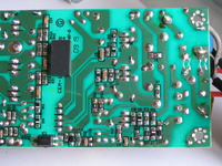
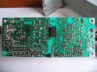
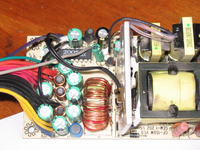
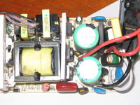
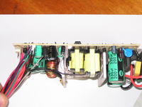
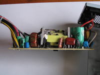
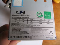
    Photos inside (straight from the camera):
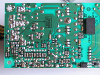
    CFI Grup CFI-S150X Model: Irregular Voltage Fluctuations on 5VSTB Pin - Possible Causes? CFI Grup CFI-S150X Model: Irregular Voltage Fluctuations on 5VSTB Pin - Possible Causes? CFI Grup CFI-S150X Model: Irregular Voltage Fluctuations on 5VSTB Pin - Possible Causes? CFI Grup CFI-S150X Model: Irregular Voltage Fluctuations on 5VSTB Pin - Possible Causes?
    CFI Grup CFI-S150X Model: Irregular Voltage Fluctuations on 5VSTB Pin - Possible Causes? CFI Grup CFI-S150X Model: Irregular Voltage Fluctuations on 5VSTB Pin - Possible Causes? CFI Grup CFI-S150X Model: Irregular Voltage Fluctuations on 5VSTB Pin - Possible Causes? CFI Grup CFI-S150X Model: Irregular Voltage Fluctuations on 5VSTB Pin - Possible Causes?
    Added after 3 [hours] 45 [minutes]:

    The problem of the AT30B integrated circuit has somewhat unraveled and I got to the copy of the note, and this is a SMPS controller certified by ATC Technology.
    I corrected TONI_2003.
  • ADVERTISEMENT
  • #2 10822546
    W.P.
    Computer PSUs specialist
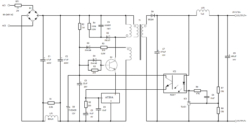
    I would start by replacing C8 (equivalent to C3 in the diagram on p. 7).
    The reason for this behavior is the PP inverter. With its voltage is powered by 2005 and hence such tensions on its legs.

    Added after 7 [minutes]: < br />

     Of course, PP side capacitors also for checking or replacing.
  • ADVERTISEMENT
  • #3 10822640
    ZbeeGin
    Level 39  
    W.P. wrote:
    I would start with replacing C8 (equivalent to C3 in the diagram on p. 7).

    Both small electrolytes on the original side (equivalents C5 and C3) were replaced with new ones. I am wondering about the voltage that persists on this Zener diode. There is a 12V diode in the application, in my power supply there is 7.9V in the power supply and it floats up to 8.1V.

    On the secondary side of the PP inverter in 5V and 15V branches, electrolytes are also replaced.
  • ADVERTISEMENT
  • #4 10822814
    W.P.
    Computer PSUs specialist
    Does R17 have 220 & # 937 ;?
  • #5 10822978
    ZbeeGin
    Level 39  
    W.P. wrote:
    Is R17 has 220 Ω?

    Yes, and the resistor is ok, it's declared 220 & # 937 ;, and the D7 diode is also working.

    Unfortunately, there was a problem with the Zener diode ZD4. The elements are glued, and when desoldering it ... a small tragedy with the amputation of one leg.

    The diode is the "D5" code, which most likely means that it is a MMSZ5230BT1G diode produced by ON Semi with a voltage of 4V7. Replacing the BZV55-C4V7 caused that the PP converter does not start at all. :cry:
  • ADVERTISEMENT
  • Helpful post
    #6 10823083
    W.P.
    Computer PSUs specialist
    CFI Grup CFI-S150X Model: Irregular Voltage Fluctuations on 5VSTB Pin - Possible Causes?
    The layout on page 7 fits quite well with this. I think that there should be a diode at 12V.
    ZbeeGin wrote:
    When the voltage behind the bridge is "normal", i.e. 285V
    < br /> This value is not normal. What about the capacitors behind the bridge 330 & micro; F / 200V. If you have any (47 ÷ 220 & micro; F / 400V), attach it to the output of the bridge and measure the voltage. At 230V AC, the capacitor should charge to more than 320V DC.
  • #7 10824009
    TONI_2003
    Moderator
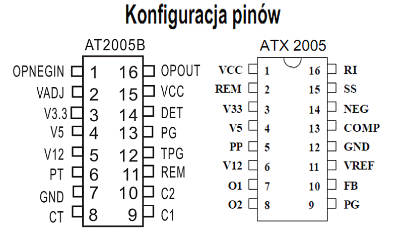
    Please tell me which pin layout of the chip matches the figure in relation to the given voltage by you ...
    CFI Grup CFI-S150X Model: Irregular Voltage Fluctuations on 5VSTB Pin - Possible Causes?
  • #8 10826702
    ZbeeGin
    Level 39  
    TONI_2003 wrote:
    Please indicate which chip chip layout corresponds to the one in the figure in relation to the given voltage by you ...

    My version of the integrated circuit is the one on the right, or ATX2005.

    W.P. wrote:
    The layout on page 7 fits quite exactly into that. I think that there should be a 12V diode there.

    It fits. Although there is one small exception. In parallel with the optocoupler there is also a Zener diode with the code "H2", a cathode directed to the optocoupler collector. If I take for granted that the codes of both diodes agree with the ON Semicondutor diodes I gave previously, then it would be just 12V. OKAY. Let's leave the unfortunate Zener diodes for now.

    Today, unfortunately, I will not push the topic further, but I hope tomorrow to find time to experiment with the condenser behind the bridge. Indeed, it should be 320V, and for me is 40V lower. There is only a thermistor on the way from the bridge ... Is it?
  • Helpful post
    #9 10827045
    W.P.
    Computer PSUs specialist
    ZbeeGin wrote:
    Although there is one small exception. In parallel with the optocoupler is the Zener diode
    It does not solve the problem but at least it helps to understand how (and why) the inverter starts.
    As for the thermistor ... I do not put it on damage but it's worth measuring its resistance - it should not exceed several ohms.

    Generally, this is a difficult problem to solve at a distance. Requires a more detailed inspection of the workshop with richer than home furnishings. It would be good to have a second AT30B in stock. It has an extensive internal structure and can be the reason for this behavior.
    In a similar situation, I would have soldered out 2005 for the time of work on PP by installing a stand in its place.
  • #10 10828444
    ZbeeGin
    Level 39  
    Today at work I measured again the voltage on the capacitors across the bridge. However, it is 351V and not as I gave 285V. The damaged Zener diode was replaced with a glass SMD 12V. The inverter starts again, but continues to sample. I can still fully confirm that at 216V on the capacitors, the PP converter starts and gives a stable 4.994V.

    W.P. wrote:
    As for the thermistor ... I do not want to damage it but you should measure its resistance - it should not exceed a few ohms.

    I have measured, it is 6 & # 937 ;.

    W.P. wrote:
    It would be good to have a second AT30B in stock

    Unfortunately, the stock is out of stock. There is also no donor, because it is in vain to search for it in my emergency ModeCom.

    TONI_2003 : SB560 diode on the + 5V line PP converter is also efficient.

    Edit: 25 Apr 2012 10:29
    CFI Grup CFI-S150X Model: Irregular Voltage Fluctuations on 5VSTB Pin - Possible Causes?
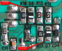
    The PP inverter is already working. Diode D7 and D8 turned out to be damaged. After replacing them with LL4148
    the inverter starts normally and the output voltages are stable. These diodes did not show any damage when measuring with a multimeter with a diode tester. Most likely, however, they get leakage at higher voltages. I can try to measure, but will it bring something important?

    Now the case of the ZD4 diode remains whether to leave this SMD 12V or should there be another diode? Currently, as the PP inverter operates normally there is a voltage of 11.6V (measurement from the oscilloscope). Before, as the mains voltage dropped to 216V and the inverter started to work, the voltage of 7V was maintained there (measurement from the oscilloscope).

    I'll throw in a few oscillograms that I did later when I sort these screenshots.
    I have corrected TONI_2003.
  • Helpful post
    #11 10831009
    TONI_2003
    Moderator
    Of course, you could experiment gently under the substitution of this Zener diode lower or higher, but since the example application You have just a Zener diode at 12V. At which everything works properly is to tempt fate (when I did not know completely what kind of diode this is what I did)? Anyway, maybe someone else will speak on this matter ...
    PS.
    When did you take measurements beforehand D7 and D8 whether they were made on soldered diodes?
  • #12 10831098
    ZbeeGin
    Level 39  
    TONI_2003 wrote:
    Of course, you could experiment slightly lower under the substitution of this Zener diode lower or higher, but if the example application You have just a Zener diode at 12V. />

    Only that the elements in the power supply are slightly different than those given in the example application. E.g:
    - R56 - application 200 & # 937 ;, here 1k Ω
    - R18 - application 330 & # 937 ;, here 150 Ω
    - R17 - application 510 & # 937 ;, 220 Ω
    So I can not fully take it for granted.

    TONI_2003 wrote:
    When did you take measurements D7 and D8 before, were they made on soldered diodes?

    Of course. Today I even measured them again. In the blocking direction, the tester shows no transition. In the direction of conduction, the diode tester indicates a decrease of 0.762V.
    ---
    Promised pair of oscillograms.
    CFI Grup CFI-S150X Model: Irregular Voltage Fluctuations on 5VSTB Pin - Possible Causes? CFI Grup CFI-S150X Model: Irregular Voltage Fluctuations on 5VSTB Pin - Possible Causes?

    CFI Grup CFI-S150X Model: Irregular Voltage Fluctuations on 5VSTB Pin - Possible Causes? CFI Grup CFI-S150X Model: Irregular Voltage Fluctuations on 5VSTB Pin - Possible Causes?
    Everything measured against the hot mass.

    Edit: 28 Apr 2012 17:47
    The PSU has passed load tests. First, the PP converter itself and later in its entirety. Output voltages of the main converter: + 5V, + 12V, -12V adhere to the ATX standard. Only 3.3V is slightly overstated. Unfortunately, the construction is quite simple and the increase is caused by the lack of active stabilization of this line with the measuring wire.
    The voltage + 5VSTB from the PP inverter under load drops to 4.995V.
    Instead of the original Zener diode ZD4, I left C12V.

    Thank you for your support. At the moment I am closing the topic.

Topic summary

The discussion revolves around irregular voltage fluctuations on the 5VSTB pin of the CFI Grup CFI-S150X power supply. The user reports issues after prolonged use, including keyboard lights flickering and difficulty powering off the computer. Initial troubleshooting involved checking and replacing electrolytic capacitors, particularly C8 and equivalents C5 and C3. The user also examined the Zener diode voltage, noting discrepancies. Further investigation revealed a damaged Zener diode (ZD4) and issues with diodes D7 and D8, which were later replaced, restoring stable output voltages. The conversation highlights the importance of measuring voltages across various components, including capacitors and resistors, and suggests that a detailed inspection may be necessary for a complete diagnosis.
Summary generated by the language model.
ADVERTISEMENT