You write a little incorrectly because they are not loaded only this is the voltage at which they give the most energy. In fact, and so it changes from the intensity of the sun. Cool, I was afraid of it being soldered out because of the paday because the very warming of the plate to spw47n60c3 had to be heated for a long time.
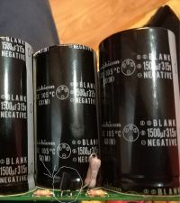
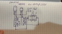
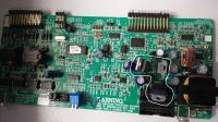
I still think 600v is too much for this inverter. After disconnecting this tape, the inverter has no chance to turn on. Must communicate first with the Dspic 30F3010 knowing that the inverter is not sure you should start from max 150V and look what will happen. The greater the voltage the worse. These capacitor transistors should not interfere with the operation of the inverter in any way but only protect the capacitors against overload in the event of an unbalanced charge because they are in series.
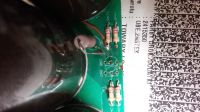
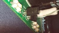
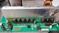
In your case, I suggest starting with the desoldering of burnt transistors Spw47n60c3 and diodes can not be there on any short circuit and between 1 and 3 foot each minimum 30 Ohm no less. It is best to desolder both diodes on the joint heat sink, leave only one on a separate one. And check if the inverter works without mppt after this one diode. If it works, you can continue working. I do not know which branch has died I need to know exactly which transistor it is. Because the first 4 are from the mppt the next 4 are in front of the separating transformer. You did not need to desolder the entire CD. The oscilloscope here and so much will not work because there is too much dependence and everything changes.
Added after 12 [hours] 47 [minutes]: Leon444 wrote: As for me, it's a waste of your time on this inverter because it is not enough to be very unreliable and very poorly made it is still buried it will be difficult to reach order and composition ...
Generally speaking, I totally agree with you because it's a bit of a mess with this company.


