logo elektroda
logo elektroda
X
logo elektroda

How to Set Logic High and Low Inputs for CMOS Chips Using Buttons in Real Circuits?

LordCompi 18966 15
ADVERTISEMENT
Treść została przetłumaczona polish » english Zobacz oryginalną wersję tematu
  • #1 11327199
    LordCompi
    Level 9  
    Hello, I'm a beginner. Based on the layout from Digital Works, I wanted to build something similar in reality.

    The thing is, I don't know how to create a low and a high. The whole system is interactive and consists of CMOS chips.

    I do not know how to pass information to the pin whether the input is 1 or 0. Can it be done with a button?

    I hope you can show me a way to solve this problem :/


    Regards
  • ADVERTISEMENT
  • Helpful post
    #2 11327282
    tos18
    Level 42  
    Simply put, the high state is the voltage close to the power supply and the low state is close to the ground potential.
    For details, please refer to the documentation of the circuits and the description of the c-mos family.
  • Helpful post
    #3 11327327
    Anonymous
    Level 1  
  • #4 11328378
    LordCompi
    Level 9  
    Ok I see. Is a 1k resistor needed for the H signal? Looking through simple logic network diagrams, I noticed that each constant logical one is connected by a 'rectangle' with the inscription 1k.

    Sorry, I'm green yet :)

    @Edit:

    So if I connect +(Vcc) through these 1k then I have a logical zero?
  • Helpful post
    #5 11328626
    Anonymous
    Level 1  
  • ADVERTISEMENT
  • #6 11330383
    LordCompi
    Level 9  
    marekzi wrote:

    LordCompi wrote:
    So if I connect +(Vcc) through these 1k then I have a logical zero?

    NO.


    One?
  • ADVERTISEMENT
  • Helpful post
    #7 11330602
    tos18
    Level 42  
    So
  • ADVERTISEMENT
  • #8 11330624
    LordCompi
    Level 9  
    :D

    And if I connect the + signal through the resistor so that it is 0.5 V, I will have 0? Do I have to connect to the negative?
  • Helpful post
    #9 11330750
    tos18
    Level 42  
    Show me such a resistor ... see in the specification of the circuit what is the input current for the c-mos system, then calculate the resistance of the resistor. Why are you afraid of connecting to ground - after all, that's how it's done. Analyze the schematics of devices based on c-mos systems. Look, there's plenty of it.
  • #10 11330920
    LordCompi
    Level 9  
    I just don't quite understand. I'm green.
    So this:
    I bought a CD4070 (4x Xor), one led and 10 1k resistors.

    Now what do I do to make this a gate that lights up if there is one on the output. It looks trivial in logic diagrams, but I don't know how it should look like in reality.

    Maybe someone can send me a picture or a picture (not schematic) of what it should look like in reality.

    Understand me, I want to understand :)

    Regards


    @Edit:

    How to Set Logic High and Low Inputs for CMOS Chips Using Buttons in Real Circuits?

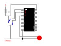
    Will the system work if it is soldered like this? The blue ones are a switch made of a needle to choose plus or minus. If not, what am I doing wrong?

    Edit: I left the pins empty for the sake of simplicity. I know they need to be connected to ground
  • #11 11331024
    tos18
    Level 42  
    My suggestion is to first explore the issue of reading schematics.
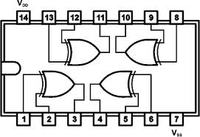
    The CD4070 looks like this
    How to Set Logic High and Low Inputs for CMOS Chips Using Buttons in Real Circuits?
    You have four identical xor gates in it. The system requires a stable and filtered power supply, as a last resort it can be a battery. You connect the power supply + to vdd(14) , - to vss(7) a 100nF ceramic capacitor connected in parallel to the power supply will be welcome. connect unused inputs to ground (5,6,8,9,12,13).
    you connect a resistor to the output (3) and the anode of the diode to it. Connect the cathode to ground. you connect inputs (1,2) to resistors and their other ends + power supply.
    you will also connect switches to the inputs so that switching on the switch causes the input to be shorted to ground (open switch is 1 on the input, closed switch is 0).
    Draw what I described and present.
  • #12 11331079
    LordCompi
    Level 9  
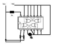
    How to Set Logic High and Low Inputs for CMOS Chips Using Buttons in Real Circuits?


    Will this work?
  • #13 11331134
    tos18
    Level 42  
    You don't read carefully. It's bad. Incorrect connection of power supply and LEDs. Who told my friend to short the outputs???
  • #14 11331141
    LordCompi
    Level 9  
    Can you show me what's wrong?

    The best in the picture
  • #15 11331192
    tos18
    Level 42  
    Unused outputs (4,10,11) are to be left free. There is no resistor for the led. The power supply of the system is not connected through a resistor. A capacitor is missing in the power supply between vdd and vss. The switches went out for a walk...
  • #16 11331225
    LordCompi
    Level 9  
    Thanks dude. I understand finally.

    I love you:*

Topic summary

The discussion revolves around building an interactive system using CMOS chips, specifically focusing on how to create high and low states for input signals. The high state is defined as a voltage close to the power supply, while the low state is near ground potential. Users are advised to connect a button to toggle between these states, using resistors to stabilize the signals. The CD4070 XOR gate is mentioned as a component for the project, with guidance provided on proper connections, including the need for a stable power supply, the use of capacitors, and the correct placement of resistors and LEDs. The importance of reading schematics and understanding circuit documentation is emphasized for beginners.
Summary generated by the language model.
ADVERTISEMENT