logo elektroda
logo elektroda
X
logo elektroda

Assessing Cable Losses for a 45m, 6mm² Cable in a 24V Solar Installation with Four Panels

motabaRESMAR 25917 23
ADVERTISEMENT
Treść została przetłumaczona polish » english Zobacz oryginalną wersję tematu
  • #1 12049943
    motabaRESMAR
    Level 9  
    Hello, I bought a few things from which I am going to create a small solar power plant, namely:

    4 solar panels with parameters:

    Voc(V): 44.4
    Isc(A): 5.35
    Vmpp(V): 35.4
    Imp(A): 5.08

    Two 120 ah batteries (24V system)
    24V/30A charge controller

    My problem is that I will have to place the solar panels as much as 45 meters from the regulator (there will be batteries directly behind the regulator)
    6mm² cable
    What cable losses can I expect?
    I connected one panel for the test this month it charged 1A and the idling voltage was 38-44 V
    But will everything work fine if they are connected to four panels in the summer when the current will be much higher? Will the voltage on the cable drop to such an extent that the batteries will not be charged?
    Please help
  • ADVERTISEMENT
  • Helpful post
    #2 12050007
    korrus666
    Level 40  
    The voltage drop at a current of 5 A on a 6 mm2 cable and a length of 45 m will be in the range of 1.2-1.5 V.
  • ADVERTISEMENT
  • #3 12050013
    motabaRESMAR
    Level 9  
    And what will be the drop at, for example, 25 A??
  • Helpful post
    #4 12050325
    wieswas
    Level 34  
    Exactly 5 times bigger, or 6V
    Power loss on the wires P=U*I=6V*25A=150W
    Think about whether the panels should not be connected in series and only the inverter charging the batteries would be "step-down" lowering the voltage.
  • ADVERTISEMENT
  • #5 12050336
    motabaRESMAR
    Level 9  
    Thank you, but another question because the panel has:
    Voc(V): 44.4
    Vmpp(V): 35.4
    The voltage at the maximum power point is 35.3V, i.e. if the panels give 25A, the batteries will be charged at 35V-6V(losses)=29V
    Does it calculate correctly? i.e. the batteries will continue to charge, this voltage drop will not affect the charging speed, because even 28V is enough to charge the batteries
    that's how it works???
  • Helpful post
    #6 12051110
    wieswas
    Level 34  
    Yes.
    The battery, however, will not be charged directly only by the charge controller. I don't know what his requirements are. What voltage is it charging at? Does it introduce its own voltage drop as it is in analog regulators? Or can it increase the supplied voltage and start charging from a dozen or so volts?
    In any case, it's a bit of a pity that 150W of power lost on the wires during strong sunlight. This is 17% of the maximum power.
  • #7 12692706
    putas
    Renewable energy sources specialist
    motabaRESMAR have you already done the installation?
    How did this voltage drop thing end up?
    I have an even longer cable at home and to minimize losses at reasonable cable costs, I used an Al4 * 16 earth cable - bridged with 2 wires, i.e. as if I had a 2 * 32 cable.
    The cost of the cable is reasonable and the losses are small.
  • #8 12775593
    kogan77
    Level 17  
    Maybe my practical knowledge will be useful for your considerations.

    Installation 1kW, drops on the cable like hell. All types of wires, pompously called "solar" in the industry, were tested.
    In desperation, I listened to my friend and ..... barely noticeable drops. Distance 43m to the regulator. Speaker cable made in Poland made of copper made in Poland, which is considered one of the best in the world!
  • #9 12775849
    CzystyZYSK
    Level 24  
    Solar cables are used for several reasons:

    - double insulation, high rated insulation voltage - 1 kV, in larger systems where the strings are 20-30 modules, they are dimensioned for max. voltage up to 1 kV. Speaker cable or even with 300/500V insulation will not do.

    - resistance of the insulation to high temperatures and UV rays - giving an ordinary cable to UV and frost, the insulation will crumble very quickly and will become linden

    If you have cables buried/released in a UV-resistant sheath and you do not exceed the rated voltage of the insulation, there is no problem ;-)

    As putas wrote, ground cables with ALU are the cheapest.
  • #10 12778878
    lukaz
    Level 14  
    Buddy motabaRESMAR, check for what maximum voltage you have a charging regulator like up to 100V, you can connect 2 in series.
    I have a regulator for 150V and I have almost identical panels connected 3 in series and I have small voltage drops on the cables and it is only 2.5 mm.
  • #11 12780832
    luke666
    Level 33  
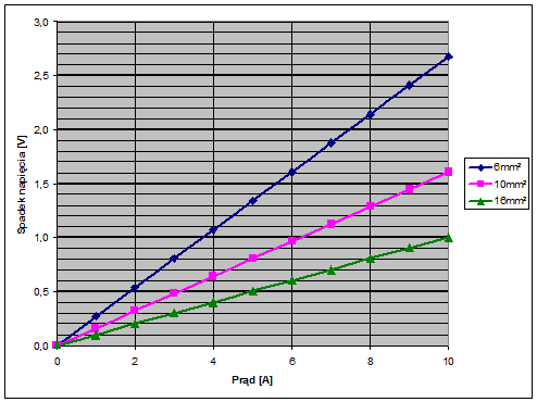
    Here you have a graph of the voltage drop versus current value for three different wire cross-sections. Due to direct current, the total length of the cable on which the voltage drop occurs is 90 m.
    Assessing Cable Losses for a 45m, 6mm² Cable in a 24V Solar Installation with Four Panels
  • ADVERTISEMENT
  • #12 13102220
    wnoto
    Level 34  
    CzystyZYSK wrote:
    As putas wrote, ground cables with ALU are the cheapest.


    Are these still for sale? I take it it's aluminum? Is there one core?
    Supposedly, a strand (weave of many threads) is better for transmitting electricity.
  • #13 13102323
    putas
    Renewable energy sources specialist
    wnoto wrote:
    CzystyZYSK wrote:
    As putas wrote, ground cables with ALU are the cheapest.


    Are these still for sale? I take it it's aluminum? Is there one core?
    Supposedly, a strand (weave of many threads) is better for transmitting electricity.


    Yes, such cables are still used. Especially as main connections.
    From what I remember from years ago, many strands are important at higher frequencies, because then the current flows mainly on the outer part of each strand in the cable. At 50Hz, and even more so at DC, it doesn't matter. Correct me if I'm wrong.
    The cable is only easier to lead - it is softer, but a bit more expensive. With smaller diameters it doesn't matter much. I put AL 4 * 16 and no problem. But such Al 4 * 50 - it must be a chore.
    Ground cables are probably always wire, overhead cables are stranded, but they have weaker insulation, which is important at high voltages (up to 1kV).
  • #14 13202294
    iwi1
    Level 17  
    Hello.
    One more thing I'm wondering about. At the moment I have 3 panels 24V/230W connected in parallel. Cable length 13m (3x2x2.5mm2 YDYp) At 30A the voltage drop is high and I want to replace these cables with 6mm2 LGY in the spring.
    I have room for 4 wires 6mm2 or 6 wires 4mm2
    But now the question - maybe secular, but a man is learning all the time
    How will it be better to connect it: three wires to pluses independently and 1 common to minus or two in parallel?
    It would be best if I connected these panels in series and bought a 72-80V heater, but ultimately I will add 6 more panels and use a 240V heater, and at the moment in 2014 I want to use what I have on the equipment.
    and the question of link or wire. A colleague above wrote that for direct current it does not matter - is it true?
  • #15 13202376
    putas
    Renewable energy sources specialist
    iwi1 wrote:
    How will it be better to connect it: three wires to pluses independently and 1 common to minus or two in parallel?

    2 out of + and 2 out of - for sure.
    Or 1 thick and 3 thinner.
    Remember that the same current flows in + and -. So both must have a sufficient cross section.
  • #16 13202411
    iwi1
    Level 17  
    putas wrote:

    Remember that the same current flows in + and -. So both must have a sufficient cross section.

    that's what physics says, and in practice the plus wire always heats up :)
    So, summing up, it turns out that the voltage drop on 13m wires must be counted as a drop on both plus and minus wires, or treated as one 26m wire.
    and here in the thread someone raised the topic of the Step-down converter. Can it be done cheaply? for 24V - because then I would connect these 3 panels and the converter in series and it's ready (only it is supposed to withstand 30A output)
  • #17 13202467
    putas
    Renewable energy sources specialist
    iwi1 wrote:
    in practice, the positive wire always heats up :)

    First time I hear it, but I'm young...
  • #18 13202527
    retrofood
    VIP Meritorious for electroda.pl
    iwi1 wrote:

    So, summing up, it turns out that the voltage drop on 13m wires must be counted as a drop on both plus and minus wires, or treated as one 26m wire.


    Voltage drop

    iwi1 wrote:
    putas wrote:

    Remember that the same current flows in + and -. So both must have a sufficient cross section.

    that's what physics says, and in practice the plus wire always heats up :)


    Any alternative electrical engineering?
  • #19 13438897
    delir203
    Level 12  
    Hello
    I'm looking for good advice. I have panels at a distance of 57m from the house, I want to connect them to the inverter and here's the question What cable to use, I read other posts on this topic and it's hard for me to choose. Please help.
  • #20 13440155
    CzystyZYSK
    Level 24  
    Give the parameters of the strings - what voltages and currents.
  • #21 13451098
    delir203
    Level 12  
    The inverter will install the main cable in the house and wants to run a distance of 38 m from the house to the garage. Behind the garage, there is a solartrack 260V and 5A voltage 20m away, it will build a shed on which it will also install panels, the distance of the shed from the garage is 25m. The inverter has 3 strings, so far it wants to use one by connecting the solar track, the rest for expansion. What cables should be used to minimize losses? Does this solution make sense at all?
  • #22 13451631
    Lesio_Q
    Level 20  
    putas wrote:
    iwi1 wrote:
    in practice, the positive wire always heats up :)

    First time I hear it, but I'm young...

    Putas-Joker ;-)

    Yeah, the plus one gets hotter statistically more often, because the minus often goes to the ground or to the ground. But all this when the device catches a puncture, not in normal operation.
    Piotr.K
  • #23 13454925
    CzystyZYSK
    Level 24  
    delir203 wrote:
    The inverter will install the main cable in the house and wants to run a distance of 38 m from the house to the garage. Behind the garage, there is a solartrack 260V and 5A voltage 20m away, it will build a shed on which it will also install panels, the distance of the shed from the garage is 25m. The inverter has 3 strings, so far it wants to use one by connecting the solar track, the rest for expansion. What cables should be used to minimize losses? Does this solution make sense at all?


    Hello

    Congratulations on your purchase ;-)

    as for the voltage drop, at 80m, 5A, 4mm2 cable gives us:

    Percent voltage drop: 0.79%

    with 2.5mm2 cable:

    Percent voltage drop: 1.19%

    difference 0.4% ;-)

Topic summary

The discussion revolves around assessing cable losses in a solar installation with four panels, where the panels are located 45 meters from the charge controller. The user inquires about the expected voltage drop using a 6mm² cable at various current levels, particularly when charging batteries. Responses indicate that at 5A, the voltage drop is approximately 1.2-1.5V, while at 25A, it could reach around 6V, resulting in significant power loss (150W). Suggestions include considering series connections for the panels to reduce losses and ensuring the charge controller's voltage requirements are met. The importance of using appropriate cables, such as solar-rated cables with high insulation resistance, is emphasized to minimize losses and withstand environmental factors. Practical experiences shared highlight the effectiveness of using thicker cables or alternative types to reduce voltage drops.
Summary generated by the language model.
ADVERTISEMENT