logo elektroda
logo elektroda
X
logo elektroda

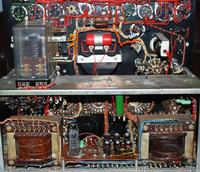
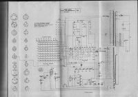
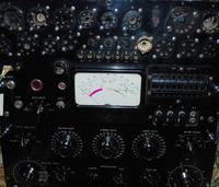
Seeking Electronic Diagram for 1963 Polish Valve Characteristic Meter Type P507

grandemarius 7161 6
ADVERTISEMENT
  • #1 12273385
    grandemarius
    Level 2  
    With respect, if it is possible, please help me to get the Electronic Diagram for Valve Characteristic Meter Type P507 - Made in Poland (1963).

    I fixed some precision resistors made like in a coil (I found them interrupted) from slope divider circuit (x1, x2, x3, x4, x5), but I don't know the precision value for these.

    If it is possible I need also a complete Instruction Manual or User Guide and a complete Table of Codes for Electronic Valves. I own some of them but I don't know how complete they are.

    Thank you, everybody !
    Seeking Electronic Diagram for 1963 Polish Valve Characteristic Meter Type P507 Seeking Electronic Diagram for 1963 Polish Valve Characteristic Meter Type P507
  • ADVERTISEMENT
  • ADVERTISEMENT
  • #3 12273757
    grandemarius
    Level 2  
    I hope this information is very helpful for me.

    I think my problem was R26, R27, R28, R29. These were interrupted and I restored them from remaining wire pieces, obtaining a smaller value than 600 ohms. Now I will put it o.k. for a precision measure.

    If there will appear any news about this instrument documentation, please notice me again. In the future I want to make a complete documentation.

    Thank You very much! All respect for Your work!
  • ADVERTISEMENT
  • #4 21284495
    zdenoeddie
    Level 2  
    >>12273566 @TM85 do you have these documents still, please? I've got this equipment but without any papers. Thanks very much!
  • ADVERTISEMENT
  • #6 21285624
    zdenoeddie
    Level 2  
    >>21284819 Thank you very very much! Dziękuję!
  • #7 21297901
    zdenoeddie
    Level 2  
    Cześć to everybody.
    Is it possible, that "current" relay can be faulty on P507 please?
    If I measure bigger tube (like 6L6, El34,...) when current goes over approx. 40-50mA device goes to faulty state (red bulb). But this current threshold is changing randomly.
    If I understand correctly circuitry, the anode (and G2) current is sensed by this "current sense" relay only (in P508 there is few more parts around).
    Thanks.

Topic summary

The discussion centers on obtaining the electronic schematic, instruction manual, and valve code tables for the 1963 Polish Valve Characteristic Meter Type P507 (ELPO Miernik Lamp Elektronowych P 507). The original poster repaired interrupted precision resistors in the slope divider circuit (x1 to x5) but lacked exact resistance values. Provided resources include schematic files and a Polish manual from trioda.com and chomikuj.pl. Further inquiries address potential faults in the current sensing relay, which triggers a fault state at variable current thresholds (around 40-50mA) when testing larger tubes like 6L6 or EL34. The relay senses anode and screen grid (G2) currents, with noted differences in circuitry compared to the P508 model. The community shares documentation and troubleshooting insights to support restoration and accurate measurement with the P507 device.
Summary generated by the language model.
ADVERTISEMENT