logo elektroda
logo elektroda
X
logo elektroda

Old Polish radio Amator 2B stereo (DSS201) - schematic diagram, gallery

p.kaczmarek2 3165 19
ADVERTISEMENT
Treść została przetłumaczona polish » english Zobacz oryginalną wersję tematu
  • Old Polish radio Amator 2B stereo (DSS201) - schematic diagram, gallery .
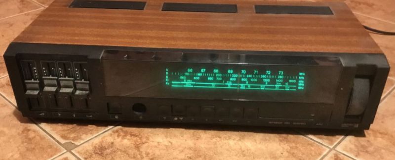
    Here I will present another popular piece of equipment from the communist era - the Amator radio, or more precisely the 2B version (DSS201). The Amator 2B differs from the Amator 2 in that it has no tuning indicator.
    Amator 2 allowed the reception of long wave, medium wave, short wave and FM frequency ranges. The AM intermediate frequency was 465kHz and FM 10.7MHz. Details later in the diagram, and now pictures.
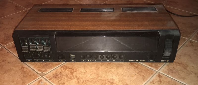
    Front and top with the characteristic three vent inserts:
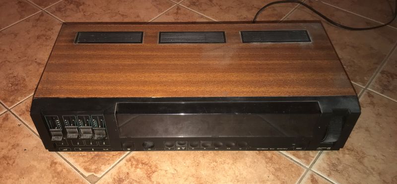
    Old Polish radio Amator 2B stereo (DSS201) - schematic diagram, gallery Old Polish radio Amator 2B stereo (DSS201) - schematic diagram, gallery .
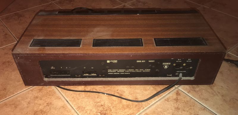
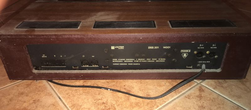
    Rear:
    Old Polish radio Amator 2B stereo (DSS201) - schematic diagram, gallery Old Polish radio Amator 2B stereo (DSS201) - schematic diagram, gallery .
    It is also worth adding that there is a fuse hiding at the bottom of the case to be removed:
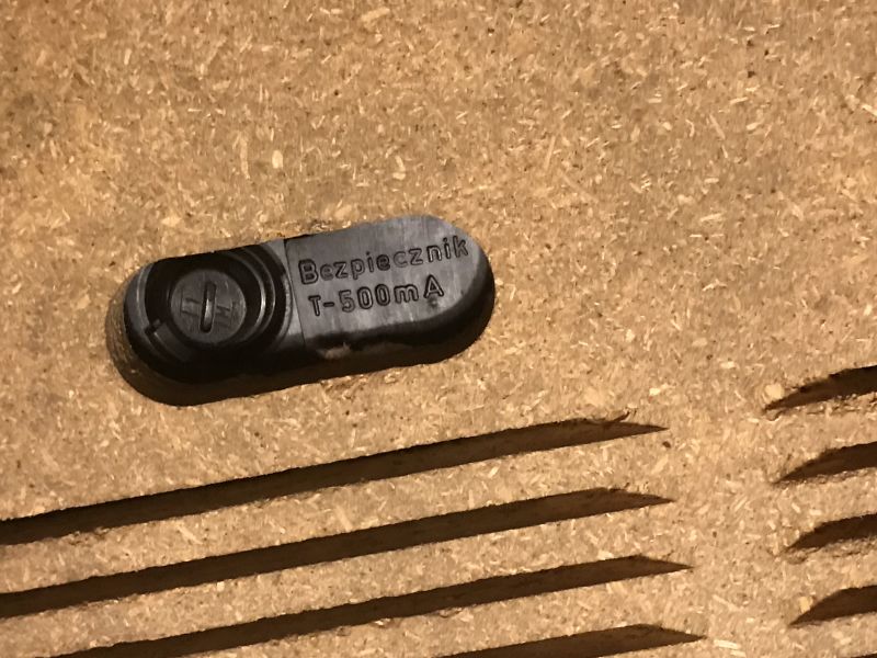
    Old Polish radio Amator 2B stereo (DSS201) - schematic diagram, gallery .
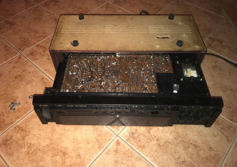
    Looking inside:
    Old Polish radio Amator 2B stereo (DSS201) - schematic diagram, gallery .
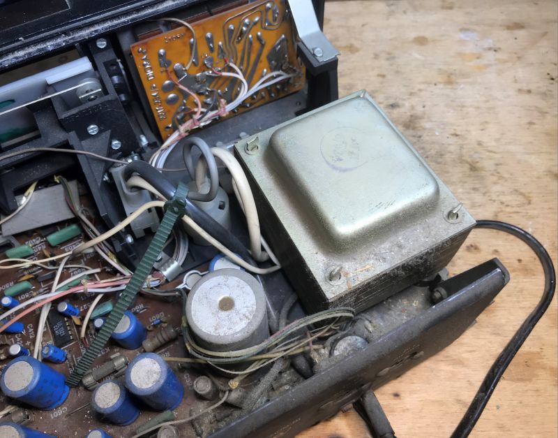
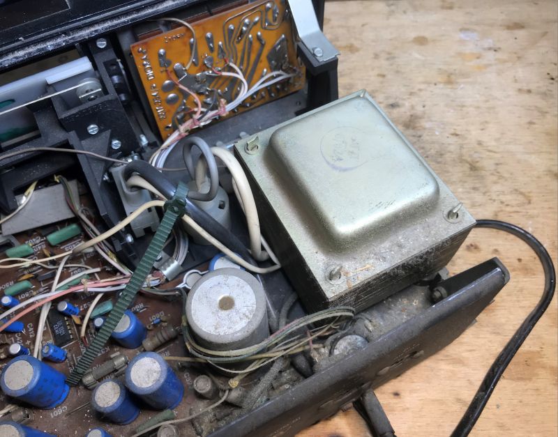
    Let's start perhaps with the power supply, of course there is a 50Hz mains transformer:
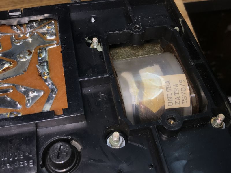
    Old Polish radio Amator 2B stereo (DSS201) - schematic diagram, gallery Old Polish radio Amator 2B stereo (DSS201) - schematic diagram, gallery .
    You can see the fuse and the separate PCB from the slide potentiometers:
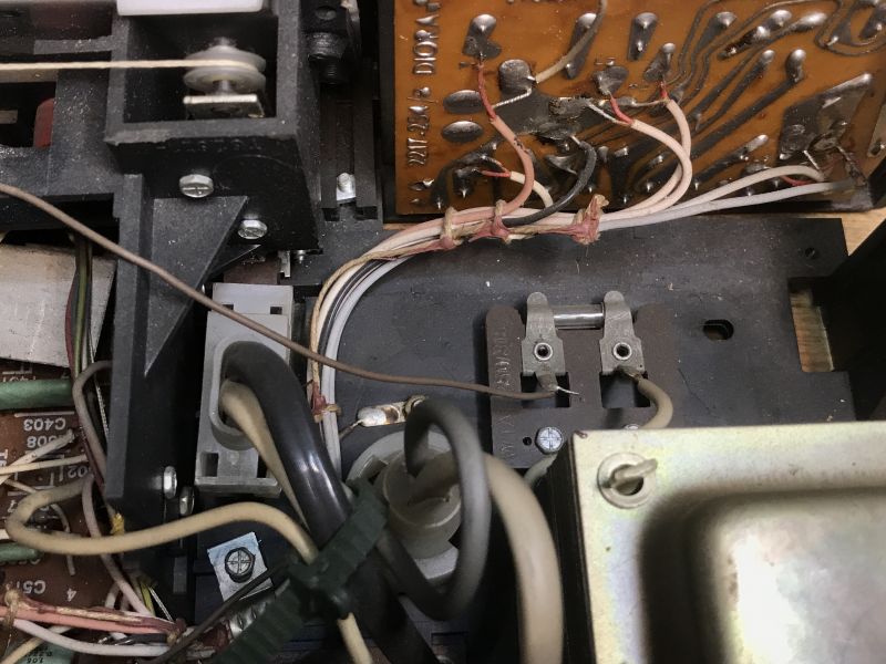
    Old Polish radio Amator 2B stereo (DSS201) - schematic diagram, gallery Old Polish radio Amator 2B stereo (DSS201) - schematic diagram, gallery
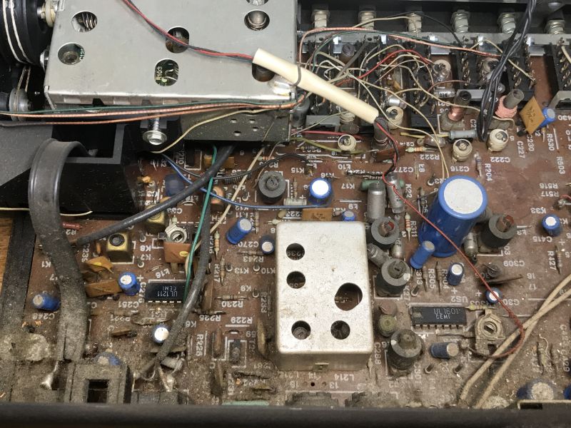
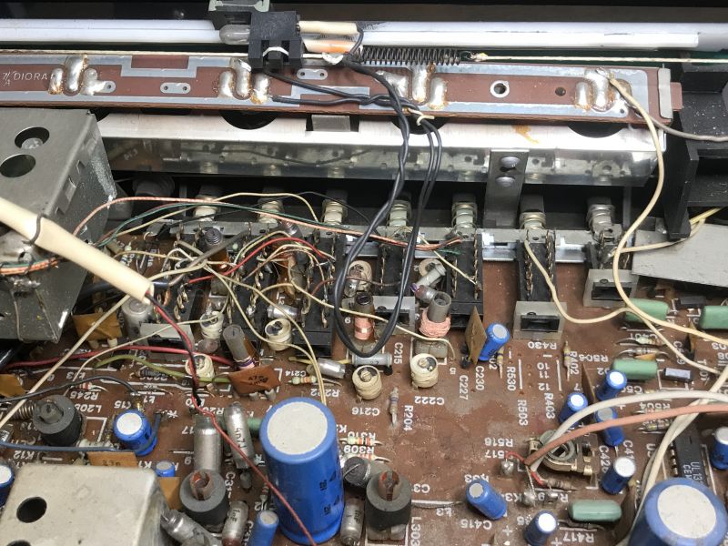
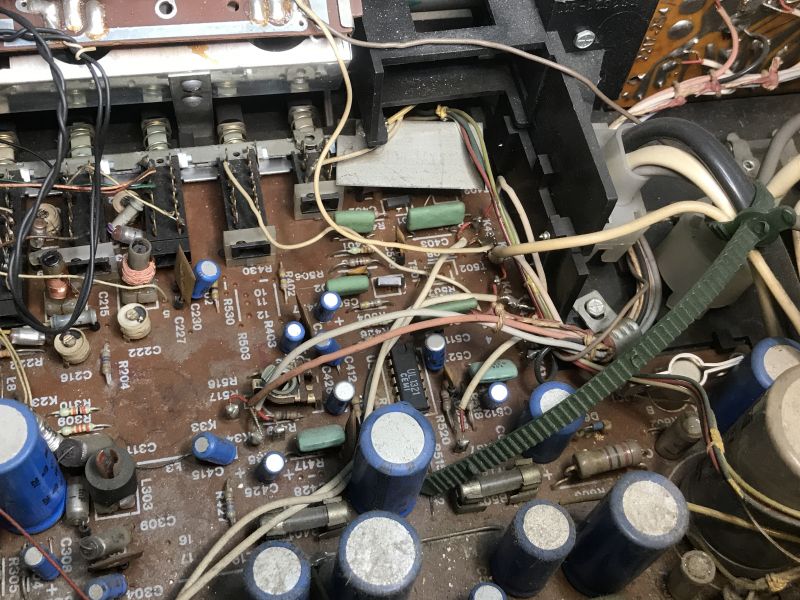
    PCB, isostat type buttons, tuning scale;
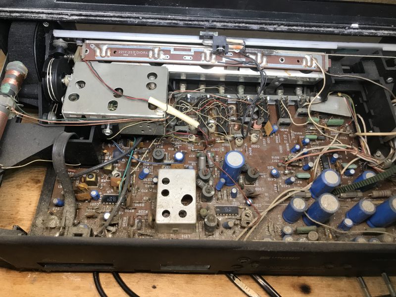
    Old Polish radio Amator 2B stereo (DSS201) - schematic diagram, gallery Old Polish radio Amator 2B stereo (DSS201) - schematic diagram, gallery Old Polish radio Amator 2B stereo (DSS201) - schematic diagram, gallery Old Polish radio Amator 2B stereo (DSS201) - schematic diagram, gallery Old Polish radio Amator 2B stereo (DSS201) - schematic diagram, gallery .
    CEMI, UL1321, UL1601, UL1211 circuits can be seen.
    Elwa electrolytic capacitors:
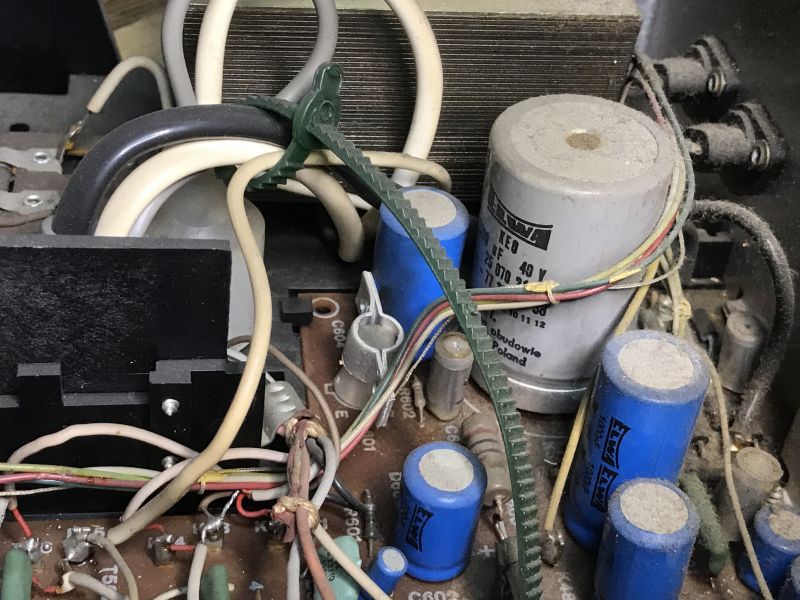
    Old Polish radio Amator 2B stereo (DSS201) - schematic diagram, gallery .
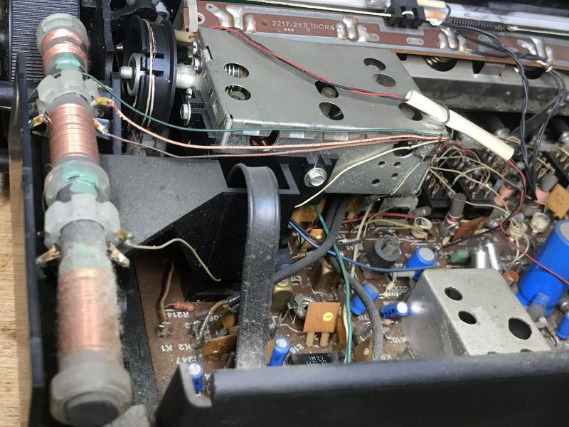
    Tuning mechanism and bulb (incandescent, not LED) from backlight:
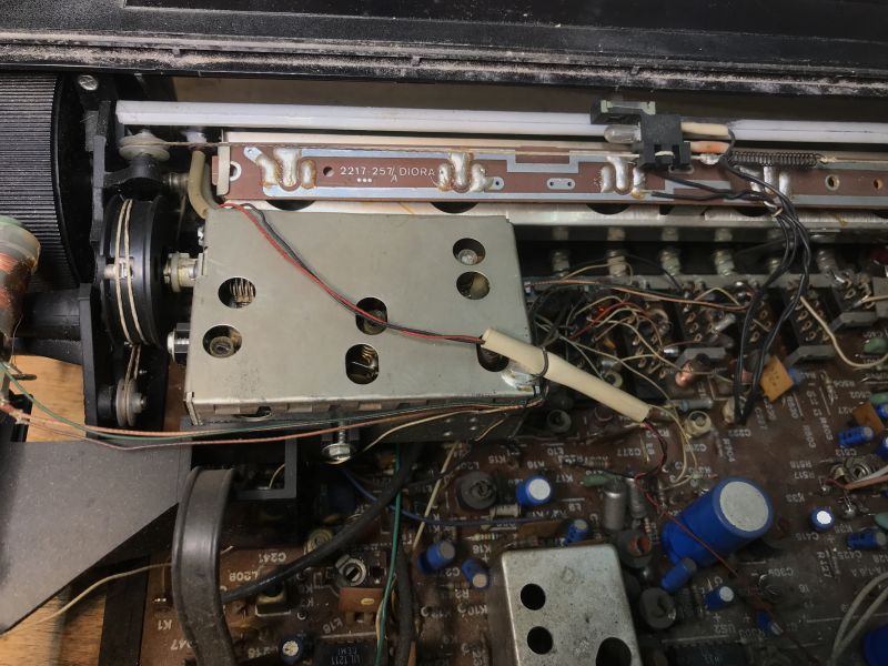
    Old Polish radio Amator 2B stereo (DSS201) - schematic diagram, gallery .
    I really like the tuning mechanisms on these types of old radios. This is probably because I grew up with much newer equipment. Here you can see how the bulb is fixed:


    .
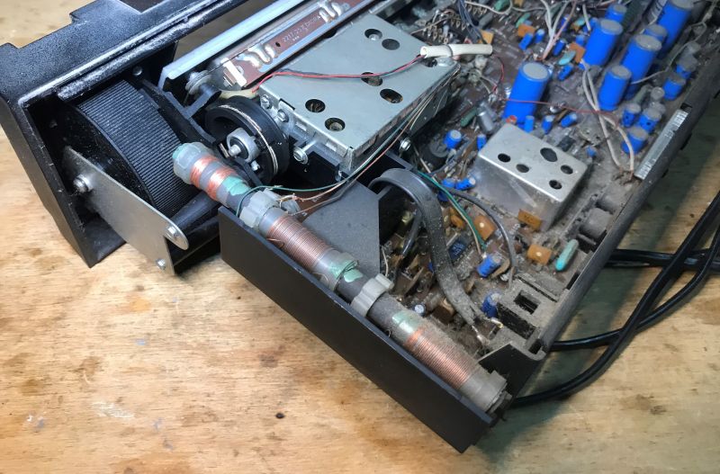
    Ferrite antenna:
    Old Polish radio Amator 2B stereo (DSS201) - schematic diagram, gallery Old Polish radio Amator 2B stereo (DSS201) - schematic diagram, gallery
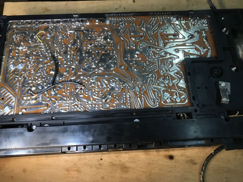
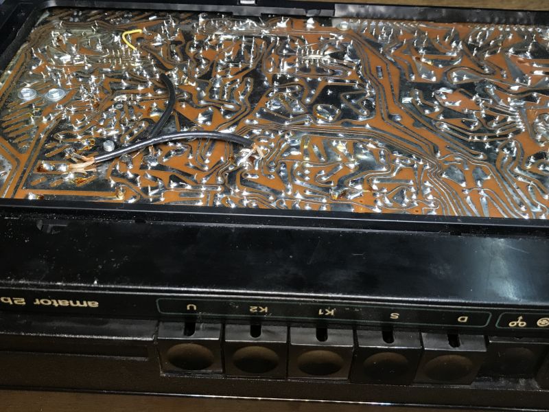
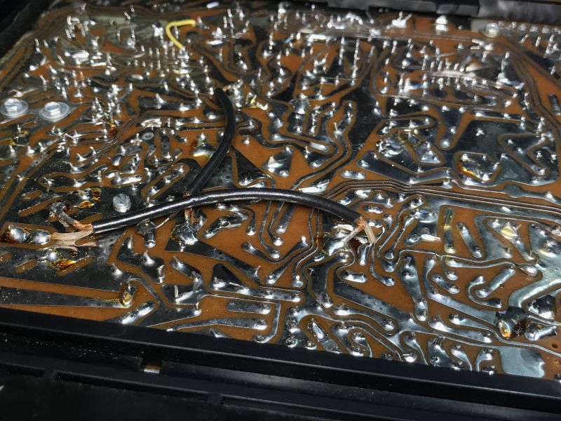
    PCB underside:
    Old Polish radio Amator 2B stereo (DSS201) - schematic diagram, gallery Old Polish radio Amator 2B stereo (DSS201) - schematic diagram, gallery Old Polish radio Amator 2B stereo (DSS201) - schematic diagram, gallery .
    However, photos can't show everything. It's time for a bit of documentation.

    Schematic of the Amator 2 stereo:
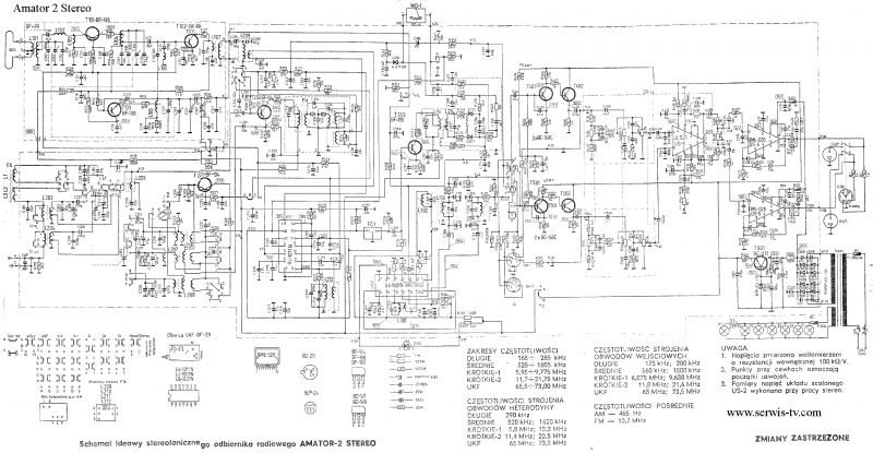
    Old Polish radio Amator 2B stereo (DSS201) - schematic diagram, gallery .
    UL1321 (dual acoustic preamplifier circuit):
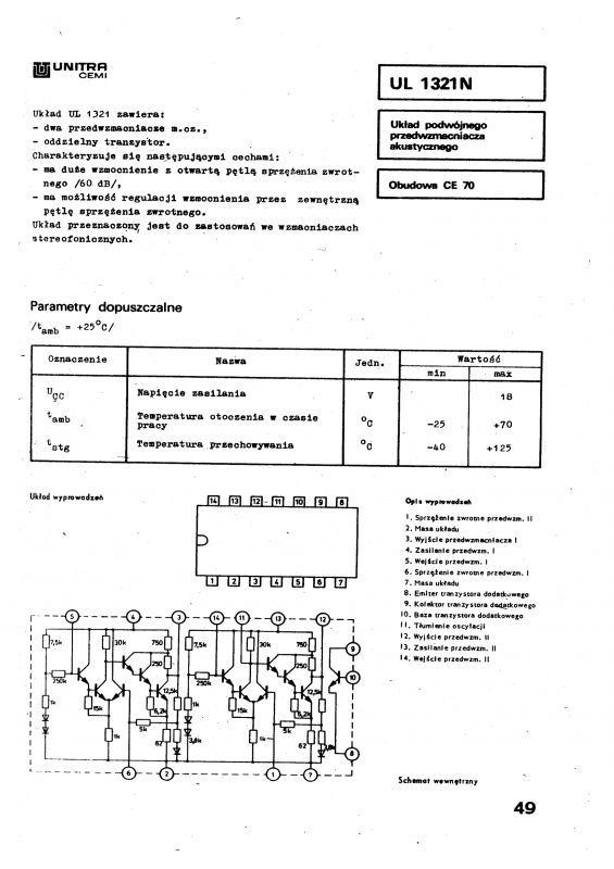
    Old Polish radio Amator 2B stereo (DSS201) - schematic diagram, gallery .
    UL1601 (stereo signal decoder circuit):
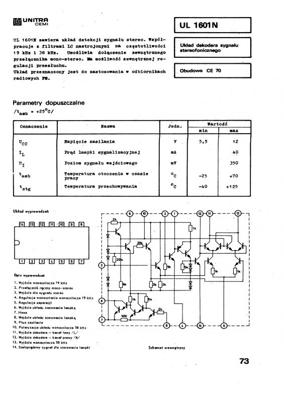
    Old Polish radio Amator 2B stereo (DSS201) - schematic diagram, gallery .
    UL1211 (AM/FM intermediate frequency amplifier):
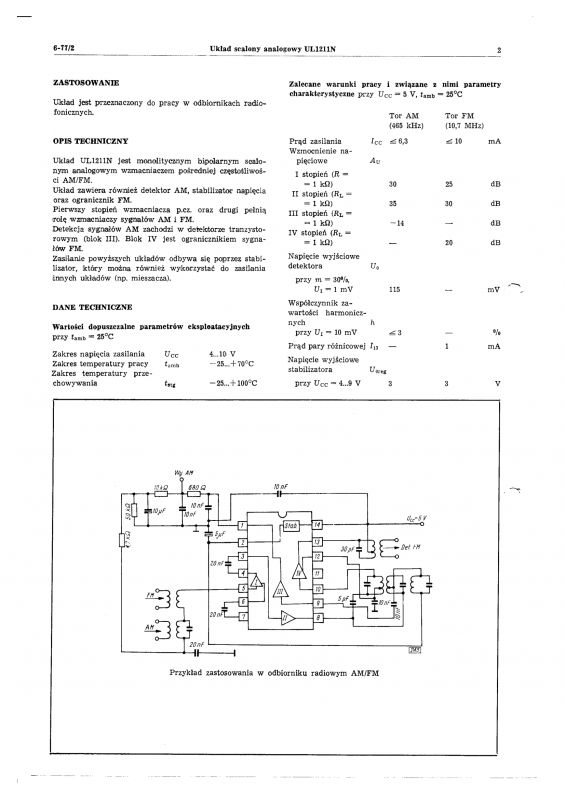
    Old Polish radio Amator 2B stereo (DSS201) - schematic diagram, gallery .
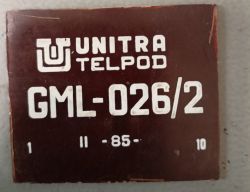
    The power amplifier is based on two GML-026s. GML-026 schematic:
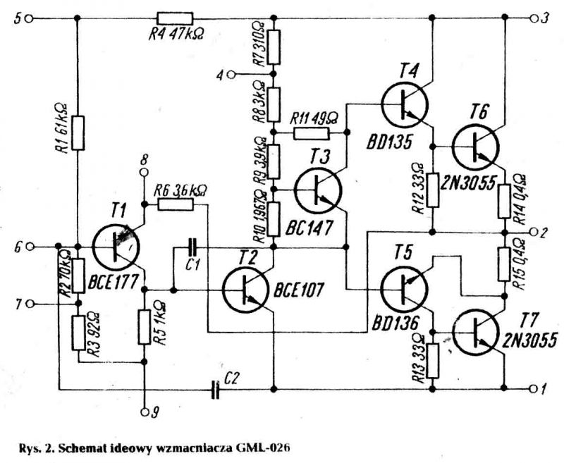
    Old Polish radio Amator 2B stereo (DSS201) - schematic diagram, gallery .
    By the way, I see now that I didn't take a photo of them, you can only see their legs in the PCB photo, so I'll use a photo from another topic:
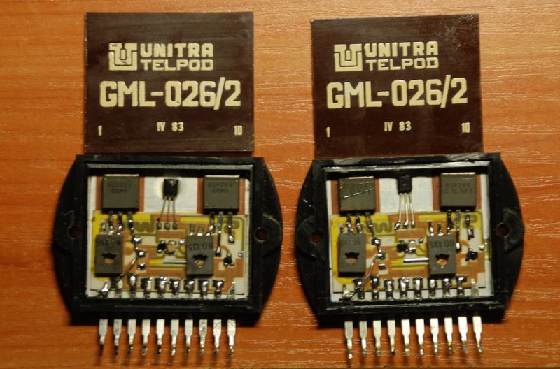
    Old Polish radio Amator 2B stereo (DSS201) - schematic diagram, gallery .
    The photos above show a slightly different circuit, GML-026/2, but I was unable to find GML-026.
    Source: https://www.elektroda.pl/rtvforum/topic1869247.html

    Summary Summary
    Radio potentially up and running. It's not that bad, spares are still obtainable, even GML-026, will there be a bargain for it? Well I don't know, but I'm happy to have shared another old radio with the forum. If anyone has similar specimens in their collection then feel free to post pictures.

    Cool? Ranking DIY
    Helpful post? Buy me a coffee.
    About Author
    p.kaczmarek2
    Moderator Smart Home
    Offline 
    p.kaczmarek2 wrote 11914 posts with rating 9980, helped 571 times. Been with us since 2014 year.
  • ADVERTISEMENT
  • #2 21071909
    szeryf3
    Level 29  
    I think it was the coolest radio I used in those days. I still feel sentimental about it to this day. I wish I had kept it until modern times.
  • ADVERTISEMENT
  • #3 21071931
    p.kaczmarek2
    Moderator Smart Home
    It is for this reason that I sometimes try to show this type of equipment in this section, even though I normally deal with digital electronics anyway. All the more reason for me to encourage others to post topics in "Equipment Interiors".
    Helpful post? Buy me a coffee.
  • ADVERTISEMENT
  • #4 21072017
    _Avalanche_
    Level 7  
    Where are the 2N3055 transistors from on the schematic of this GML?
  • ADVERTISEMENT
  • #5 21072021
    Mateusz_konstruktor
    Level 36  
    p.kaczmarek2 wrote:
    The power amplifier is based on two GML-026. GML-026 diagram:
    Old Polish radio Amator 2B stereo (DSS201) - schematic diagram, gallery .
    By the way, I see now that I didn't take a photo of them, you can only see their legs in the PCB photo, so I'll use a photo from another topic:
    Old Polish radio Amator 2B stereo (DSS201) - schematic diagram, gallery .
    Source: https://www.elektroda.pl/rtvforum/topic1869247.html
    .
    The colleague is confusing concepts.
    First of all: GML-026 and GML-026/2 are two different circuits.
    At the same time, the radio presented appears to have a factory-installed GML-026/2.
    It is impossible not to mention at the occasion of this discussion the fact that there are two variants of GML-026/2, with standard transistors mounted inside and with the structures themselves mounted inside and for this a different transistor model.
  • #6 21072035
    p.kaczmarek2
    Moderator Smart Home
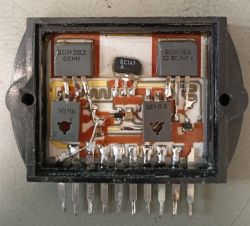
    Indeed, the photo in the linked thread shows GML-026/2 and not GML-026. When I get a chance I will take a correct photo, unless anyone has one to hand?
    Helpful post? Buy me a coffee.
  • #7 21072150
    tank_driver
    Level 17  
    Old Polish radio Amator 2B stereo (DSS201) - schematic diagram, gallery .
    These are 2N3055 structures bought with the then valuable foreign exchange, hence the later switch to locally produced power transistors,
    Please, and a beautiful description of 'our' ceramic hybrid:
    http://qann.wikidot.com/hybryd-gml
    EDIT: replacing the picture with a larger one,
  • #8 21072606
    Anonymous
    Level 1  
  • #9 21072611
    MarekS6
    Level 16  
    this article came to me perfectly here ;p I no longer need to dismantle what I have to look inside out of curiosity :-)

    Some time ago I told my neighbour that if she had any old electronic equipment to throw away, she could give it to me for parts instead of going to the PSZOK. By old, I mean late 1990s and upwards. How surprised I was when she gave me an Amateur 2 radio last week....

    To be honest, I'm wondering what to do with it - for parts it's "too old" and on the other hand I realise it's such a collector's classic and it's probably a shame to throw it away. Apparently there's one taker for it already, but I'm not hearing from him.

    Out of curiosity, I plugged the radio into the speaker and all I can hear is a hum. And all in all, no wonder, because the radio is probably not tuned (old FM range). In addition, the frequency change knob doesn't have a full range of movement - something must have mechanically shifted inside, probably this string is to be rewound/corrected.


    Old Polish radio Amator 2B stereo (DSS201) - schematic diagram, gallery .
  • #10 21072866
    szeryf3
    Level 29  
    @MarekS6 don't throw it away because it's a shame. A little work and patience and it will play and be a pleasure to the eye.

    And I found something like this and a vintage one in my stash.
    Old Polish radio Amator 2B stereo (DSS201) - schematic diagram, gallery Old Polish radio Amator 2B stereo (DSS201) - schematic diagram, gallery .
  • #11 21072901
    cirrostrato
    Level 38  
    The power supply reefs from Amators, still quite reasonably priced and in good quantity at auctions, are currently the cheapest source for rewinding into output transformers for SE and PP tube amplifiers.
  • #12 21073048
    James596
    Level 28  
    Putting the tuning cable on this receiver is something of a nightmare. The design itself seems unfriendly in terms of disassembly. The Zodiac was better done in this respect.
  • #13 21073076
    klamocik
    Level 36  
    A long time ago I just swapped the frayed line for monofilament, a horrible replacement but not to be outdone.
  • #14 21073125
    kris8888
    Level 39  
    Mateusz_konstruktor wrote:
    >>21072021 .
    First of all: GML-026 and GML-026/2 are two different circuits.
    .
    But functionally they are identical and can be used interchangeably.
  • #15 21073910
    dzg4
    Level 30  
    I own the older brother of the DSS201, in the DSS101 I inserted the LA3101 instead of the UL1321, plus the recommended blocking capacitors on the preamp inputs, it has its years and is not Hi Fi for it has a warm and pleasing sound.
  • #16 21074258
    ZbeeGin
    Level 39  
    p.kaczmarek2 wrote:
    The Amateur 2B differs from the Amateur 2 in that it has no tuning indicator.
    .
    There is also a difference in the schematic, as the preamp is made with only one transistor + UL1321.
  • #17 21075125
    kaem
    Level 29  
    James596 wrote:
    Fitting the tuning wire on this receiver is a nightmare.
    .
    I put it on in "two" with the service manual at hand and managed. In the meantime I've learned that different versions of the "Amateur" had different cable mechanisms.
    I like it if the internal cable from the socket to the UKF head unit is led with a real antenna cable (here a flat 300Ω). In the "Tosca" and I think also in the "Zodiac", they did it by hackwork (with random cables they had at hand).
  • #18 21077404
    Renegat_pol
    Level 21  
    In the 1980s I had an Amator 3. It had an orange backlight, an indicator on LEDs (red) and a "better", more powerful amplifier on a "pseudo-hybrid" (GML in discrete version, on through-hole components and 2n3055 transistors).
  • #19 21077604
    dzg4
    Level 30  
    If you'd had it when the DSS101 was produced and driven the ZG 20 with it, you'd have been a power demon on the estate :) , beautifully looking with their glowing scales with the lights off in the room. For those years the pinnacle of modernity in its class and availability in communist Poland.
  • #20 21077857
    Renegat_pol
    Level 21  
    :) I had some ZG for this. As far as I remember 25W. But as it was in my teens, it got destroyed :) .

Topic summary

The discussion centers on the Polish communist-era Amator 2B stereo radio (DSS201), highlighting its technical specifications and historical context. The Amator 2B lacks a tuning indicator, unlike the Amator 2, and supports long wave, medium wave, short wave, and FM bands with AM IF at 465 kHz and FM IF at 10.7 MHz. The radio uses the GML-026/2 hybrid amplifier module, which exists in two variants differing in transistor types, including the use of 2N3055 power transistors. These transistors were originally imported but also produced locally by brands such as Tungsram and Tesla. The tuning mechanism involves a cable that is difficult to replace, often requiring rewinding or substitution with monofilament. The Amator series is valued for its warm sound and collector status, with some users modifying or repairing components like the preamplifier (e.g., replacing UL1321 with LA3101) and noting differences in cable routing and amplifier design across versions. Power supply transformers from Amator radios are also repurposed for tube amplifier projects. The discussion includes references to related models such as DSS101, Amator 3, and other Polish radios like Tosca and Zodiac, emphasizing the cultural and technical significance of these devices in their era.
Summary generated by the language model.
ADVERTISEMENT