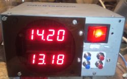
Hello
I would like to present my stereo tube amplifier, built on two PCL82 tubes. It is a very budget amplifier, the cost of production did not exceed around PLN 150.
Let's start from the beginning.
August 2020, Dominican fair in Gdańsk, while digging through the piles of antiques, I found two brand new PCL82 lamps, still in boxes. Lamps intact, price PLN 2 / piece, inside one box there is even a bill from 1975.
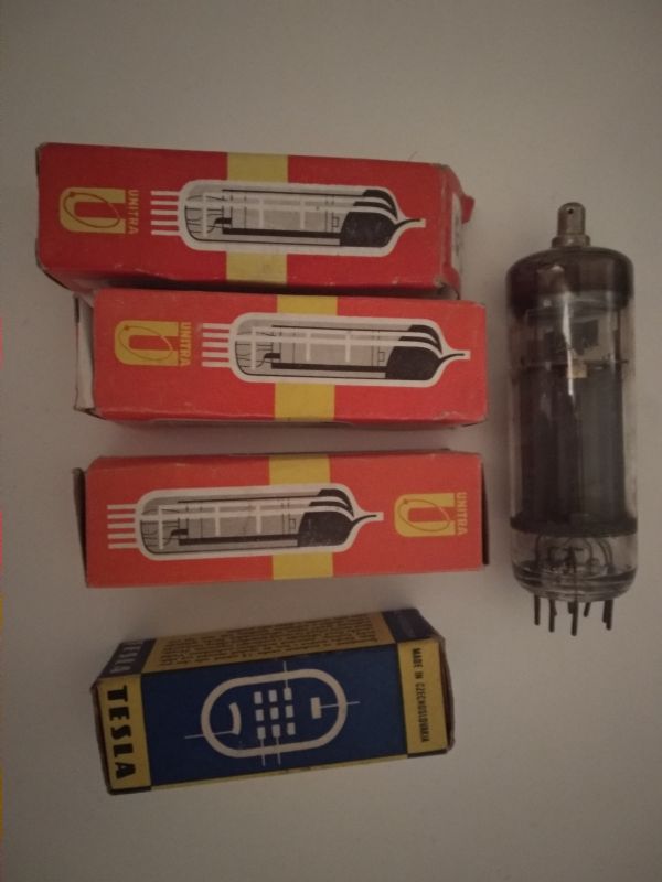
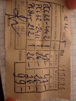
I decided to buy such lamps, because why not, PLN 4 no money and the lamps looked new. Later measurement on the meter showed the emission in both cases slightly above the catalog, i.e. the lamps are really new. One Telam, the other Polamp.
In addition to them, I also bought two used PCL86, they were supposed to be in this amplifier, but the emission measurement showed very high consumption, the emission of pentodes around 30-40%, which is total dead bodies.
We had to wait a while for the parts for further construction, but I decided to go for a very cheap option, loudspeaker transformers from aliexpress. 5k? / 4-8? ratio, power 3W.
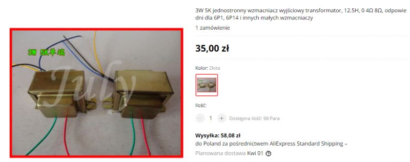
90-a pair of zlotys for two transformers? I take.
Here's what these transformers look like in real life
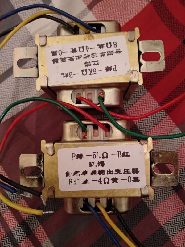
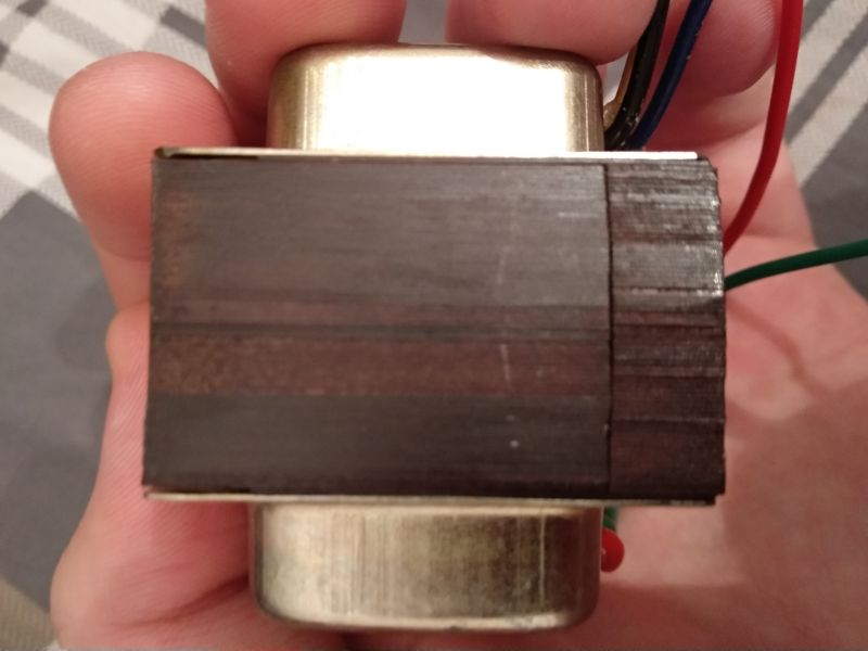
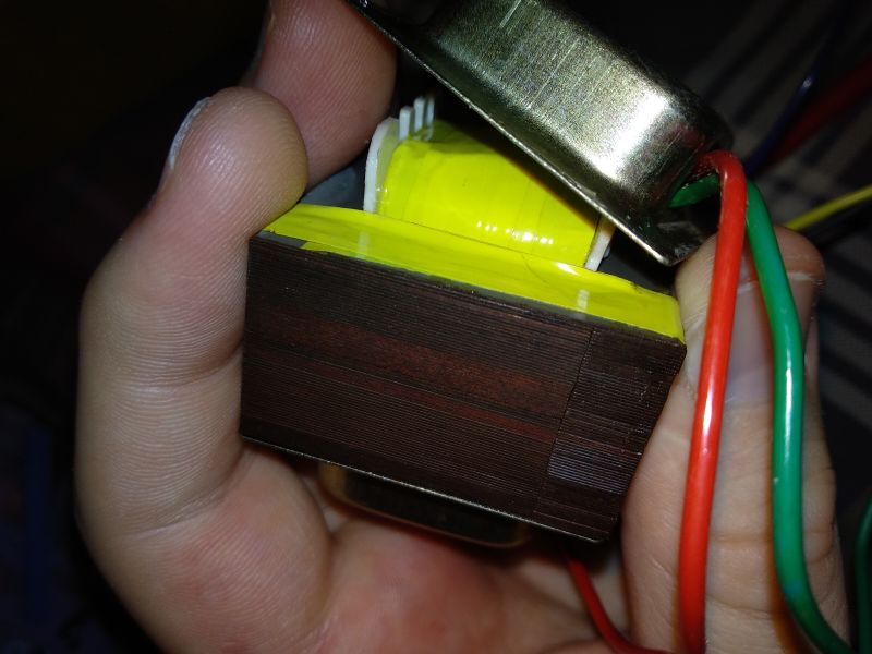
There is a gap, the performance is so-so, but we won't complain, after all, it is supposed to be a budget amplifier, not an audiophile's dream. Primary resistance approx. 500 ?.
By the way, I will notice that by connecting the 8? loudspeaker to the 4? tap, we get a load impedance of 10k?, which allows the use of very cheap and easily available PCL84 (or any lower power tube) in audio applications (for PCL84 such "atypical" load impedances were used, if you believe the catalog who described such a use).
As a housing I bought an ELGIG E145 with dimensions of 50mmx140mmx160mm (height, width, length). It cost me PLN 21.
First thing, cutting holes for lamps and fixing transformers.
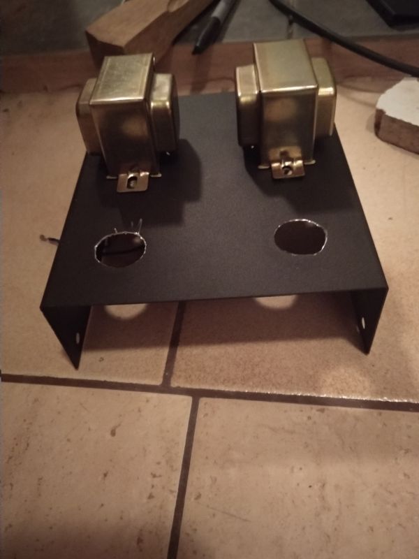
Cutting holes with a dremel is average, he slipped and made a scratch, difficult, it is right behind the lamp so not very visible. In the future I will buy a larger diameter conical drill for making holes for lamps.
Then drilling holes in the panels for banana connectors for speakers and phono sockets.
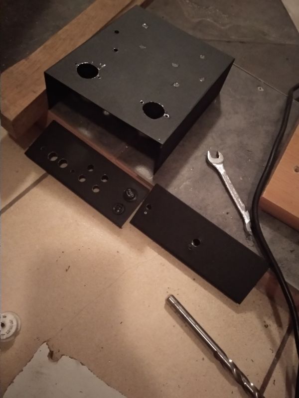
Passing OK
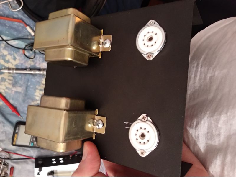
We go on, power.
The main "innovation" of this amplifier is to circumvent the problem of an expensive power transformer by using a flyback pulse power supply.
Here I refer to this thread:
https://www.elektroda.pl/rtvforum/topic3690608.html#19238925
Generally, P-lamps are very suitable for switching power supply, due to the low losses on the diodes (low current) and the possibility of series filing (one thin winding).
UCL82 where the current is only 100mA would be even more advantageous.
The lamps are heated from the first tap (12w) of 48 secondary turns.
Voltage about 40V + resistors 30? 10W and 10? 2W in order to break the voltage, the current around 310mA, i.e. we are within ? 5%.
As for the anode ones, we have 185V, which is enough.
There was some perturbation along the way with the determination of the appropriate primary current. This power supply works all the time with a constant key current, the voltage feedback basically does not work.
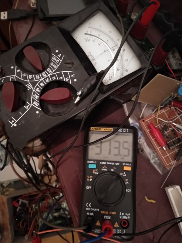
The power supply after the first try-outs.
Then the beam from the cinch to the potentiometer at the front (logarithmic 2x50k? .
.
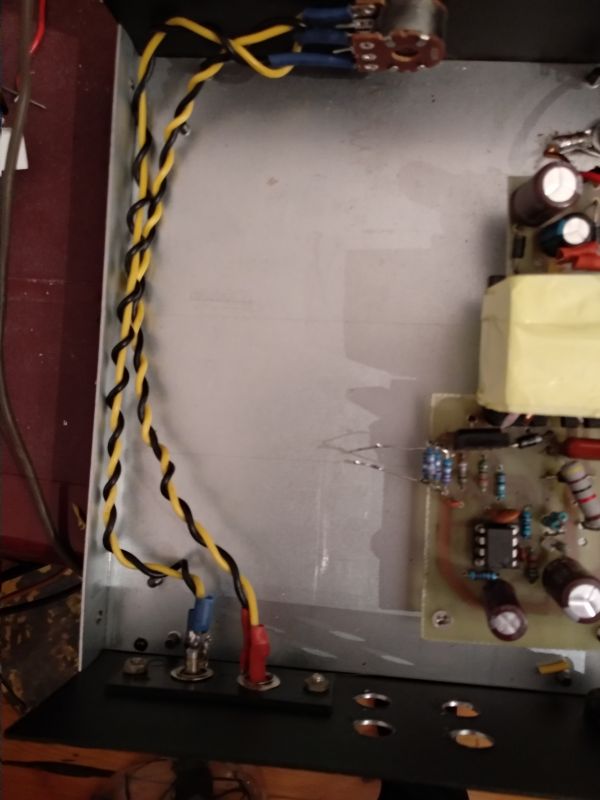
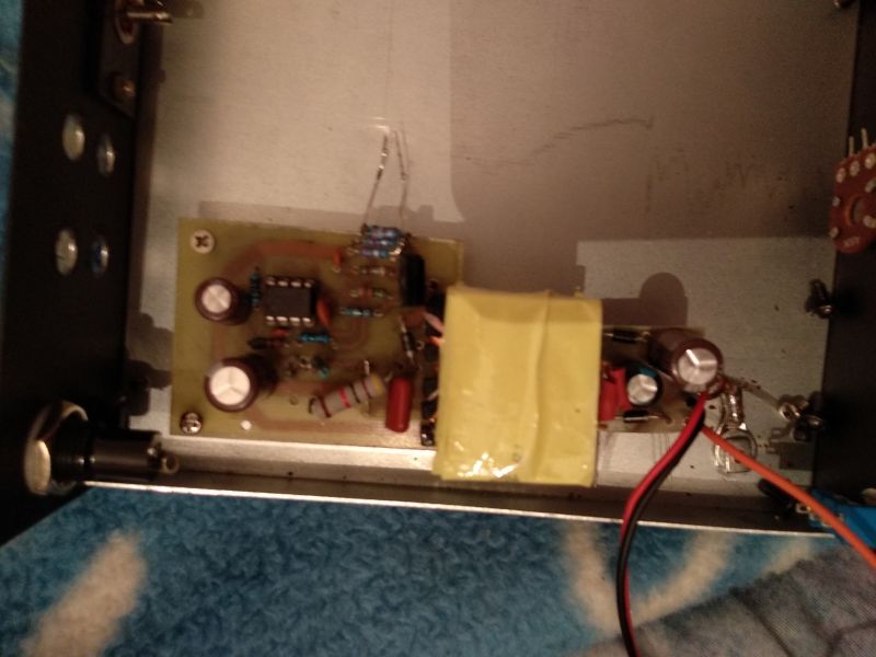
When it comes to construction, it is a simple matter, we solder directly to lamp sockets and other construction elements.
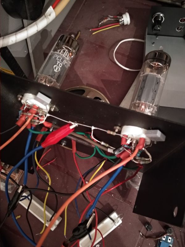
The interior looks like this:
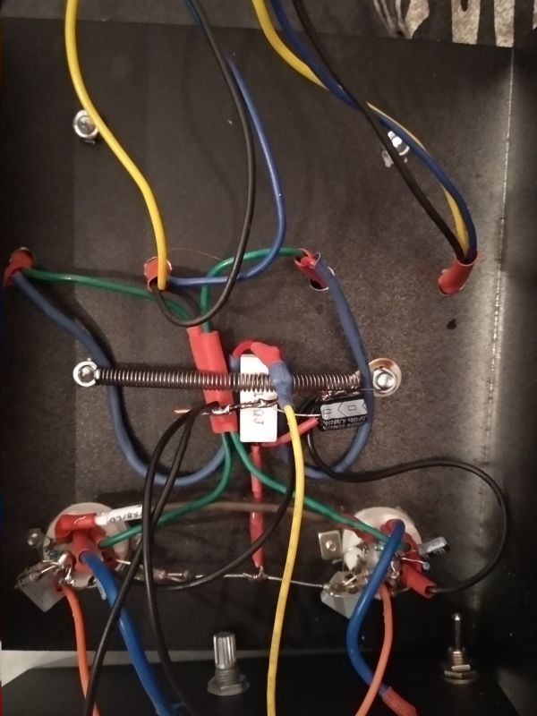
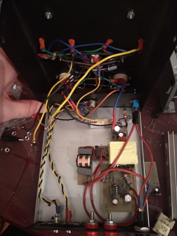
The glow is detachable through the usual 4.8mm slides, so you can easily disconnect, then unscrew the volume potentiometer and the connection to the loudspeaker sockets. The serviceability is also fairly maintained.
As for the scheme:
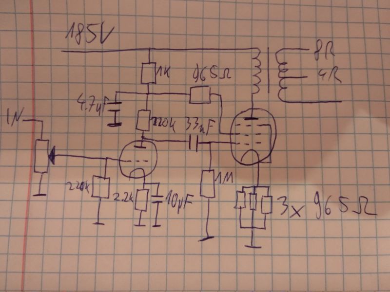
Nothing revealing, a simple amplifier based on a combination tube. I would also like to remind you that the potentiometer has 2x50k?, also the input impedance is significantly lowered compared to a traditional tube amp.
The pentode does not have a capacitor in the cathode, because PCL82 itself is not a king of no distortion (from what I have read, the catalog data is significantly exaggerated in favor), so it is worth giving some negative feedback, also to reduce the gain that we have underneath abundance.
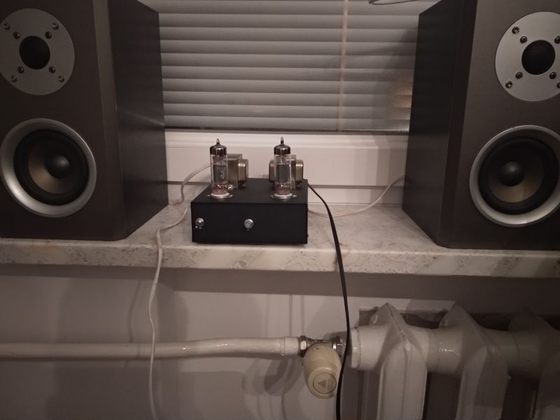
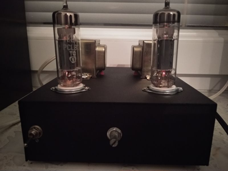
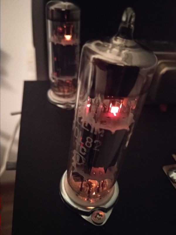
The amplifier looks not bad, although it is a subjective matter, it is definitely not without flaws and distortions, but for PLN 150 I do not complain.
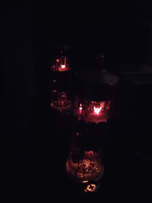
I still add a video presentation
Music: ??? ? - ? ?? ? ?
There is a slight hum, but it's not very noticeable.
Live sound is definitely better than in the movie shot with the phone.
And you have to get the potentiometer knob, that's all and so much.
I built and presented this amplifier, because many people think that a tube amplifier is something expensive and requires components for a lot of money. I built it cheaply, using normally available components, I didn't spend much, and I also have my "tinsel" playing in the room.
I would like to present my stereo tube amplifier, built on two PCL82 tubes. It is a very budget amplifier, the cost of production did not exceed around PLN 150.
Let's start from the beginning.
August 2020, Dominican fair in Gdańsk, while digging through the piles of antiques, I found two brand new PCL82 lamps, still in boxes. Lamps intact, price PLN 2 / piece, inside one box there is even a bill from 1975.


I decided to buy such lamps, because why not, PLN 4 no money and the lamps looked new. Later measurement on the meter showed the emission in both cases slightly above the catalog, i.e. the lamps are really new. One Telam, the other Polamp.
In addition to them, I also bought two used PCL86, they were supposed to be in this amplifier, but the emission measurement showed very high consumption, the emission of pentodes around 30-40%, which is total dead bodies.
We had to wait a while for the parts for further construction, but I decided to go for a very cheap option, loudspeaker transformers from aliexpress. 5k? / 4-8? ratio, power 3W.

90-a pair of zlotys for two transformers? I take.
Here's what these transformers look like in real life


There is a gap, the performance is so-so, but we won't complain, after all, it is supposed to be a budget amplifier, not an audiophile's dream. Primary resistance approx. 500 ?.
By the way, I will notice that by connecting the 8? loudspeaker to the 4? tap, we get a load impedance of 10k?, which allows the use of very cheap and easily available PCL84 (or any lower power tube) in audio applications (for PCL84 such "atypical" load impedances were used, if you believe the catalog who described such a use).
As a housing I bought an ELGIG E145 with dimensions of 50mmx140mmx160mm (height, width, length). It cost me PLN 21.
First thing, cutting holes for lamps and fixing transformers.

Cutting holes with a dremel is average, he slipped and made a scratch, difficult, it is right behind the lamp so not very visible. In the future I will buy a larger diameter conical drill for making holes for lamps.
Then drilling holes in the panels for banana connectors for speakers and phono sockets.

Passing OK

We go on, power.
The main "innovation" of this amplifier is to circumvent the problem of an expensive power transformer by using a flyback pulse power supply.
Here I refer to this thread:
https://www.elektroda.pl/rtvforum/topic3690608.html#19238925
Generally, P-lamps are very suitable for switching power supply, due to the low losses on the diodes (low current) and the possibility of series filing (one thin winding).
UCL82 where the current is only 100mA would be even more advantageous.
The lamps are heated from the first tap (12w) of 48 secondary turns.
Voltage about 40V + resistors 30? 10W and 10? 2W in order to break the voltage, the current around 310mA, i.e. we are within ? 5%.
As for the anode ones, we have 185V, which is enough.
There was some perturbation along the way with the determination of the appropriate primary current. This power supply works all the time with a constant key current, the voltage feedback basically does not work.

The power supply after the first try-outs.

Then the beam from the cinch to the potentiometer at the front (logarithmic 2x50k?

When it comes to construction, it is a simple matter, we solder directly to lamp sockets and other construction elements.

The interior looks like this:


The glow is detachable through the usual 4.8mm slides, so you can easily disconnect, then unscrew the volume potentiometer and the connection to the loudspeaker sockets. The serviceability is also fairly maintained.
As for the scheme:

Nothing revealing, a simple amplifier based on a combination tube. I would also like to remind you that the potentiometer has 2x50k?, also the input impedance is significantly lowered compared to a traditional tube amp.
The pentode does not have a capacitor in the cathode, because PCL82 itself is not a king of no distortion (from what I have read, the catalog data is significantly exaggerated in favor), so it is worth giving some negative feedback, also to reduce the gain that we have underneath abundance.
The amplifier looks not bad, although it is a subjective matter, it is definitely not without flaws and distortions, but for PLN 150 I do not complain.


I still add a video presentation
Music: ??? ? - ? ?? ? ?
There is a slight hum, but it's not very noticeable.
Live sound is definitely better than in the movie shot with the phone.
And you have to get the potentiometer knob, that's all and so much.
I built and presented this amplifier, because many people think that a tube amplifier is something expensive and requires components for a lot of money. I built it cheaply, using normally available components, I didn't spend much, and I also have my "tinsel" playing in the room.
Cool? Ranking DIY


