logo elektroda
logo elektroda
X
logo elektroda

Connecting Timer Bathroom Fan: Wiring Diagram, Switch Box, and 3-Wire Cable Configuration

mariuszzidan 61218 20
ADVERTISEMENT
Treść została przetłumaczona polish » english Zobacz oryginalną wersję tematu
  • #1 13269565
    mariuszzidan
    Level 10  
    Hello. I have a problem with connecting the time fan, I will present in the pictures everything how it looks for me and I am asking for help.
    This is the fan I bought:
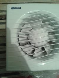
    Connecting Timer Bathroom Fan: Wiring Diagram, Switch Box, and 3-Wire Cable Configuration

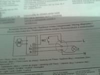
    Here is the diagram in the manual

    Connecting Timer Bathroom Fan: Wiring Diagram, Switch Box, and 3-Wire Cable Configuration ;

    Previously, I had a regular on / off switch connected to the light bulb in the bathroom connected to the contact with two brown wires like this:
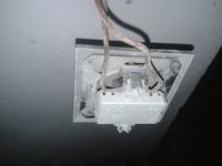
    Connecting Timer Bathroom Fan: Wiring Diagram, Switch Box, and 3-Wire Cable Configuration

    Now I let go of a new three-wire cable from this box where there is an on / off switch for the bathroom:
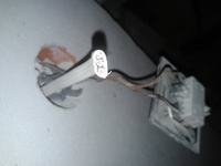
    Connecting Timer Bathroom Fan: Wiring Diagram, Switch Box, and 3-Wire Cable Configuration

    And this is what all the wires in this box with the on / off switch look like:
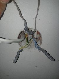
    Connecting Timer Bathroom Fan: Wiring Diagram, Switch Box, and 3-Wire Cable Configuration

    I have all electrics connected in boxes in sockets, including 3 yellow wires, as you can see, because they are probably from the socket in the bathroom and from the second switch in the bathroom. please help, how should I connect this fan.
  • ADVERTISEMENT
  • #2 13269656
    Dziaduszyn
    Level 17  
    Connect the phase and zero to 2 wires and with the third wire you only trigger the timer switch from the bulb switch.
  • ADVERTISEMENT
  • #3 13269675
    mariuszzidan
    Level 10  
    Buddy, if you could, I am asking you exactly which cable to which.
  • #4 13269727
    bajer1
    Level 32  
    Hello
    Buddy, who did this installation to you Electricians, are the wires connected like this now?
    It is very simple, but if you don't understand, take someone you know because it may end badly for you. Regards
  • #5 13269778
    mariuszzidan
    Level 10  
    The electrician has been doing an electrician with a very long internship, thank you for worrying about me, but with the connection, if I find out how to do it, I will not have a problem. I will add that in this socket there are 3 wires, each of them 3zyly yellow, brown and blue. Yellow connected together, blue also and two brown ones for the switch and the 3 connected with the brown one which goes to the switch
  • #6 13269889
    bajer1
    Level 32  
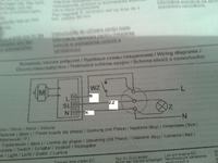
    Hello So yes, the wire you added connect Yes blue to blue yellow green to brown after the switch (bulb) and brown to brown in front of the switch where the phase is. On the other hand, the fan according to the photo. Regards
    Connecting Timer Bathroom Fan: Wiring Diagram, Switch Box, and 3-Wire Cable Configuration
  • #7 13269900
    Dziaduszyn
    Level 17  
    On 2 cables, you need to have normal power supply, as in a socket, and connect the 3rd cable to the light switch so that when the light is turned on, the phase appears on this cable.
  • #8 13269934
    mariuszzidan
    Level 10  
    Blue connect with the three blue ones that are already connected together? Yellow green to brown, or attach it with the brown one that comes in contact? And the brown one to the other brown one for contact?
  • #9 13269962
    bajer1
    Level 32  
    Hello
    Yes, only brown where there is always Phase in the switch.
    Regards
  • ADVERTISEMENT
  • #10 13269986
    mariuszzidan
    Level 10  
    I have already checked, I know where it is, tomorrow I will try to install it there and let you know how it went as the conference went, thank you very much for your help.
  • #11 13270054
    Dziaduszyn
    Level 17  
    If everything is well connected, the blue cables are zero and there is no electricity in them.
  • #12 13270076
    mariuszzidan
    Level 10  
    Well, there is no electricity, so what will it be possible to connect this cable from the fan to them? Blue 0 and the yellow ones?
  • #13 13270180
    Dziaduszyn
    Level 17  
    Do you know why Laskowik did not have light in his cabaret?
    Because it had only pluses, and not a single minus :D
    I understand that when you connect a light bulb to just any 2 cables, it always shines in your home?
    You need 3 things on this cable
    - 0
    - PHASE
    -RELEASE
    I am writing this for the third time, maybe you will finally read it.
  • #14 13270624
    bajer1
    Level 32  
    Hello
    Do as we write to you and don't write anything else yet :D
    Regards
  • #15 13270694
    mariuszzidan
    Level 10  
    All right good gentlemen take it easy :) I only asked because I know that this is more or less the case that not every cable has a plus :) But I like to ask to know more sometimes :)
  • ADVERTISEMENT
  • Helpful post
    #16 13270792
    niewolno2
    Level 40  
    Gentlemen, do not forget that the yellow-green wire is reserved only as a protective conductor.
    Protective conductor (PE) - an electric conductor for protection against electric shock. It can be a grounding conductor (connecting the main grounding terminal with the grounding electrode) or equipotential bonding (ensuring equalization of electrical potentials of various live parts). Two-color insulation - yellow-green (always).
  • #17 13280899
    serwisant73
    VIP Meritorious for electroda.pl
    niewolno2 wrote:

    Gentlemen, do not forget that the yellow-green wire is reserved only as a protective conductor.
    Protective conductor (PE) - an electric conductor for protection against electric shock. It can be a grounding conductor (connecting the main grounding terminal with the grounding electrode) or equipotential bonding (ensuring equalization of electrical potentials of various live parts). Two-color insulation - yellow-green (always).


    That's right. So all the deliberations directing the interested person to adapt this cable as the Control cable are rather at odds with standards and safety ...
    It turns out that the electrician, when laying the installation, did not take into account that perhaps an additional wire would be needed ... Standard for Polish electricians ... Especially those with long experience.
  • #18 13283268
    mariuszzidan
    Level 10  
    Thank you for your help, I connected it as my colleague bajer1 wrote and everything works fine ;)
  • #19 16599216
    naszybko
    Level 10  
    Hello, I would like to dig out the thread in order not to create a new one, because the topic is very similar.
    I have a fan with a time-clock function installed in the bathroom, I know the principle of operation and everything is connected correctly.
    Plus to plus, zero to zero, the bell switch is on the second plus (the one that gives the impulse). Everything works as it should, after firing the fan, it works as long as the timer is set.
    The question is (because there are no comments about it in the manual), can I replace the bell switch with a standard two-pole switch and will it not have a negative impact on the electronics in the fan?
    The effect I would like to achieve: I turn on the fan, it starts because it gets a pulse, but the switch stays on. As a result, the fan does not turn off until the current in the 'impulse' wire is cut off. After being turned off with the switch, the fan works from that moment on as long as the timer is set. Is my reasoning correct? Will it work like that and not hurt the electronics? On the contrary, will the fan be damaged by the 'continuous' current on the 'impulse' wire?
  • #20 18210698
    piotrek0411
    Level 9  
    Hello, I also have a dilemma and a question like a colleague above, can you install an ordinary switch? And we will not damage the fan or electronics? It is due to aesthetics. Please answer urgently
  • #21 18234995
    bajer1
    Level 32  
    Hello
    The voltage on the trip lead should not damage the electronics at all times.
    On this wire, the voltage activates the fan power supply system, a relay or dependent triac, which the manufacturer used after the voltage disappears, the time to switch off is counted down, if the voltage does not disappear, the system will never disconnect the fan.
    Regards

Topic summary

The discussion revolves around connecting a timer bathroom fan using a three-wire cable configuration. The user seeks assistance with wiring, having previously used a standard on/off switch. Responses clarify that the blue wires are for neutral (zero), while the brown wires are for phase connections. The yellow-green wire is designated as a protective conductor. Participants emphasize the importance of correctly connecting the wires to ensure proper fan operation and safety. The user confirms successful installation after following the provided guidance. Additional inquiries about using a standard switch instead of a bell switch for the fan's timer function are also addressed, with assurances that it will not damage the fan's electronics.
Summary generated by the language model.
ADVERTISEMENT