logo elektroda
logo elektroda
X
logo elektroda

Merlo Loader: Replacing Damaged Hydraulic Pump Controller with Two Relays

adam_sil 42513 50
ADVERTISEMENT
Treść została przetłumaczona polish » english Zobacz oryginalną wersję tematu
  • #1 14142401
    adam_sil
    Level 20  
    Hello
    If the forum misplaced then I apologize and ask the admin to put the topic in the appropriate section.

    In the Merlo loader died electronic controller that controls the electrovalves in the hydraulic pump. To begin with, a diagram of the conversion :
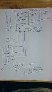
    Merlo Loader: Replacing Damaged Hydraulic Pump Controller with Two Relays

    In the original version, the regulated voltage from the controller smoothly controlled the movement of the valves so that the loader does not move rapidly but slowly depending on the value of the potentiometer located near the pedal. This is important especially during charging - it pulls up slowly and not abruptly.
    I replaced the controller with two relays that switch 12V to the valves depending on the setting of the direction lever. The relays are switched by shorting the minus to the case near the pedal (instead of the factory potentiometer).
    Everything works beautifully only that the charger starts violently. So I came up with an ego solenoid for the solenoid valves. I will place the regulator potentiometer at the pedal.
    And here a request to you esteemed forumers to give me some scheme of the regulator that will work best here.
    The maximum voltage that will flow into the regulator is 14.4 volts, the minimum voltage probably does not have to be 0 or 1 because I do not believe that 1volt will move the solenoid valve enough to get the charger going. As for the control current, it is quite high and measurements showed that it was 19-20A at times. Also a higher power regulator is needed. Thanks in advance for your answers....
  • ADVERTISEMENT
  • #2 14142526
    artibpl
    Level 17  
    And the loader is under the supervision of the UDT?
  • #3 14143096
    adam_sil
    Level 20  
    Maybe you didn't read, but I was asking about the voltage regulator schematic and the question of whether it is under supervision is not related to this topic and will not help in any way to solve this problem - well, except to score you points
  • #4 14144483
    Anonymous
    Anonymous  
  • #5 14144661
    adam_sil
    Level 20  
    Okay tomorrow I will try to read something from them

    szelton wrote:


    Your circuit will not pass the test, because if one of these additional relays is tripped then 12V goes to the valve which is full open and that is why it jerks.


    Why do you say it will not work? I cut the wires from the controller and all control goes through relays at the moment. When I move the forward direction lever the voltage goes to the coil of the relay (let's call it #1 ) but it doesn't get switched on because I have the pedal depressed, which disconnects my coil circuit. Only when I let go of the pedal does the coil circuit of the relay close, this in turn short-circuits the contacts and full 12V flows to the valve and the charger starts rapidly. It is the same with the reverse movement - the reversing lever gives voltage to the coil of relay No. 2 and the same thing continues. When you add a regulator, the ground will be connected permanently. So
    if the voltage of 12V applied to the valves through the relay contacts will be regulated by a potentiometer at the pedal, then when the pedal is depressed to the stop and the shift lever is moved, for example, forward, the relay coil will turn on, but the charger will not start because no voltage will flow through the contacts. Only when you let go of the pedal will a slowly increasing voltage flow through the relay contacts and the supercharger should start more smoothly because the valve will open more slowly.
    If the pedal is not depressed and I move the directional lever then it will jerk but if the pedal is depressed it must move slowly :) .
  • #6 14144694
    Anonymous
    Anonymous  
  • #7 14146050
    adam_sil
    Level 20  
    Nothing can be read from the valves, but I found a plate on the pump. It is a Sauer Danfoss. I wrote down all the numbers:
    Model number 508668
    Model code 90R075FASNN8D
    P7C6 DB1 GMA
    484830E101
  • #8 14147730
    waldek63
    Level 16  
    Hi what is the symbol of this controller and give the Full name of the machine and the engine number I will try to get you the electrical documentation to mod¿ print I need to have this data take a photo of the controller and post it
  • #9 14148771
    adam_sil
    Level 20  
    The symbol I gave on the schematic is Susmic 25 from Sauer, the wiring diagram I already have. I have nothing after the schematic. The matter is about replacing the original controller with a controller of my own design.
    So it's just a matter of some electrical schematic of the voltage regulator that will smoothly control these valves. As this is about designing a voltage regulator for proportional solenoid valves, I ask the admin to move the topic to the Electronics Design section and change the topic, for example, to Need a schematic of a regulator that controls proportional solenoid valves. If that is not possible then I will close this topic and open in the above mentioned section
  • ADVERTISEMENT
  • #11 14150563
    waldek63
    Level 16  
    And it is not by any chance a hydraulic block with manifolds, because if so, you need the correct sequence of switching on the solenoids of the solenoids here voltage regulation does nothing and it will not help you. The solenoid has two states on or off, and the manifold may have two solenoids and depending on the type. On the block of these distributors there may be a couple of pieces draw me some schematic and take a photo and send me an email. As for the schematic of the controller itself, such a thing does not exist services do not repair this type of thing, insert a new one adopt it with a diagnostic modem and you are done. Please contact me greeted something remotely we will work out. Greetings. Waldek 63
    elektrykautomatk k63(_at_)interia.pl
  • ADVERTISEMENT
  • #12 14151067
    adam_sil
    Level 20  
    bonanza wrote:


    Basically, this is what I mean.


    Here is the schematic

    Merlo Loader: Replacing Damaged Hydraulic Pump Controller with Two Relays

    I think the valves are controlled by voltage (current ?). There are two pieces on the pump, each has two pins. There is a 5kohm potentiometer at the pedal. In addition, there is a speed sensor connected to the controller, probably the shaft. The valves were controlled both by pressing-releasing the pedal and by measuring the engine speed. Because if I threw the direction lever, for example, forward without pressing the accelerator, the machine stood still. When I slowly pressed the gas pedal the machine slowly moved. If, for example, I wanted to scoop something I needed higher engine speed. Then I adjusted the speed with the pedal (potentiometer located next to the pedal. My modification will exclude the first way of starting the machine ( when using the shaft speed sensor).
    I could be tempted to build a more elaborate controller but there is no point. If I understand correctly, the maximum current that is needed to control the coil I will calculate from ohm's law. I just need to measure the resistance of the coil, the control voltage I already know - it's 10-12V. Just need to calculate the current and you can build a regulator :) What do you guys think, am I thinking right ?
  • #13 14153372
    waldek63
    Level 16  
    Hello Dear Colleague solenoid valves are designed only to open there is no question of any regulation accept it . Control valves have a completely different design instead of a solenoid they have a servo mechanism (motor) I do not understand you mean to control the hydromotor or actuators . If the machine starts without touching the gas or jerks then the pump is to be regenerated or one of the control valves suspended it can be checked in the following way, you can fasten the bucket of the loader to something and raise the front observing whether the power does not fall as it falls unfortunately the pump to be regenerated bypassing the safeguards can cause permanent damage to the pump. resistance should be within the range of 18 R (ohm) 50 R depending on the type, pay attention to whether the solenoid valves when you turn it on are tapping NOTE THE COIL CONTAINS A POLARIZING diode Reverse connection will damage the diode and the coil to regenerate the driver as far as I can see it is not so strongly complicated is to repair and you can handle it with my hint question to you are an electronics technician my tel. 517986593 greetings
    Waldek63
  • #14 14154815
    pafciowaw
    Automation specialist
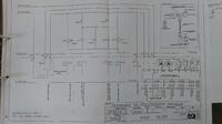
    Colleagues...judging by the original schematic, these two valves (SV Low Speed and SV High Speed) are used to switch the low or high flow from the pump (switching and switching based on the signal from the foot pedal/potentiometer and the shaft rotation sensor); while the direction of travel is realized by RL20 and RL21.
    If this schematic is true for the machine with which Col. Adam_sil has a problem with, then the reworking of the control (to bypass the original controller) must go in the direction of creating such a control pedal that would give 3 states: off, low speed, high speed (and with this -> powering the valves); possibly converting the linear signal (voltage divider on the potentiometer) into useful switching thresholds.
  • #15 14157692
    adam_sil
    Level 20  
    pafciowaw wrote:
    Colleagues...judging from the original schematic, these two valves (SV Low Speed and SV High Speed) are used to switch the low or high flow from the pump (switching and switching based on the signal from the foot pedal/potentiometer and the shaft rotation sensor); while the direction of travel is realized by RL20 and RL21.


    The two speeds are realized by a micro switch located on the direction lever and indicated by an indicator light. Originally, it was pressing the accelerator pedal and - let's call the other pedal the clutch - the clutch that changed the speed only within the range of specified speeds. Pressing the switch acts as if I had engaged half a gear - the supercharger responds the same way to pedal pressure except that it goes slower or faster depending on the state of the miko switch. After the fault, RL20 and RL21 switch on depending on the position of the direction lever, but the machine stood still. The measurement showed a lack of control voltage on the coils, so I installed relays there. In this way I circumvented the faulty servo control of the coils by the controller.
    The loader is a Merlo kt 33.7 The resistance of the coils is 5.5 ohms. So after calculations, the regulator should give an amperage of about 2A

    I'll look for some schematic and assemble it quickly. It won't hurt to try and maybe it will work as I expect it to
  • #16 14158228
    pafciowaw
    Automation specialist
    You are talking about "microswitch speed gear". - yes, you can use it according to your schematic (with additional relays) and you will get two speeds (speed).
    This will work, but the original controller analyzed simultaneously: the pressure on the pedal (inch pedal see square), the speed sensor of the speed gear in question (turn sensor of the speed gear) and the rotation of the shaft (engine revs on flywheel) and the direction of travel....
  • #17 14158331
    adam_sil
    Level 20  
    "Microswitch speed gear" works, only the signal "forward solenoid valve" and "reverse solenoid valve" is missing. Probably some final stage ( transistor, thyristor, current amplifier ?) died. I tried to reach the controller but it is flooded with something resembling windshield glue. The board in the housing is turned with the print facing up. I would have to actually destroy the aluminum housing without damaging the electronics. I gave up on the grounds that it could end up worse than it is at the moment.
  • ADVERTISEMENT
  • #18 14175358
    adam_sil
    Level 20  
    So I looked through a lot of regulator schematics, I even found topics on elektroda.pl about proportional valve control and decided to use a pwm regulator. Due to lack of time to construct my own, I purchased it in the form of an AVT kit. It has infinite current regulation and a load capacity of up to 4A without the use of a heat sink. I will just have to rework it a bit to use the original position sensor (potentiometer) located at the pedal with a value of 5kohm (the one in the regulator is 10kohm). I'm waiting for the shipment and we'll see if it works.
  • #19 14602077
    azalewsk
    Level 13  
    I had a similar problem. There are two coils with proportional control. One for forward, the other for reverse. The problem is with setting the pwm for the beginning when the machine starts to move and the end of the adjustment, when further increasing the pwm no longer gives an increase in oil flow. With a working regulator this is done with the bodas service program with hasp on a USB key. Check if signals from the engine speed on the flywheel are coming to the controller.
  • #20 14624578
    adam_sil
    Level 20  
    Thanks for your interest mate. In my case, the controller is bankrupt. I used such a controller at my place in the beginning https://www.elektroda.pl/rtvforum/topic2940955.html .
    Everything works beautifully, but.... when I change with the pedal the position of the 5kohm potentiometer in such a way that the charger drives up slowly, the anti-short circuit in this controller is triggered and it goes into standby. You have to press the button every now and then to restart the controller. This was quite a nuisance. Now I did a test with such a regulator https://www.elektroda.pl/rtvforum/topic792460.html but during slow driving it deposits such a load on the resistor that smoke goes from it. In addition, the 555 cube heats up a lot. the performance of the valves themselves is satisfactory. So I either manage to convert this ukaład somehow or buy something like this: http://www.google.pl/url?sa=t&rct=j&q=&esrc=s...pTNNcVKJd8pFd2g&bvm=bv.91071109,d.bGg&cad=rja only I do not know if it is still on sale.
  • #21 14631214
    azalewsk
    Level 13  
    I took apart the defective controller from merlo the older one in the black case (the red LED was on permanently) The solenoid valves are controlled from BTS44 circuits. The resistance of the coils is about 2.5 ohms. For DC current it will be at 12V about 5A, at 100Hz about 3A. I have prepared a prototype on PIC16F876A and TCA4426 and 2 MOS p-channel transistors. I am currently writing a program for the processor in assembler. I already have a routine written for programming the driving potentiometer and handling PWM. Currently I have to let it go a bit because I have an overload of work, I will try to pull further in June.
  • #22 14665898
    adam_sil
    Level 20  
    How did you manage to remove that ground that is flooded inside this controller?
    In my case the coils are 5.5 ohms. Browsing the electrode forum, I came across a similar topic in which someone recommended a ready-made device for controlling such valves and, in addition, using the same potentiometer that is mounted at the pedal (5 kohm). The device is fully customizable (frequency, rise I, etc.) Here is a link to the description http://www.google.pl/url?sa=t&rct=j&q=&esrc=s...pTNNcVKJd8pFd2g&bvm=bv.92291466,d.bGQ&cad=rja. The cost of this regulator is +/- 500zl - just a fraction of the price of a new controller. I've tested several PWM controllers and each had some drawbacks. In general, the problem with them is that they work effectively only in a certain range of the potentiometer ("grab" only from the middle of the range which makes it difficult to manipulate the pedal). Also, I am determined to buy this regulator. How it will perform I will describe on the electrode.
  • #23 14670306
    azalewsk
    Level 13  
    I measured the parameters of the pulses on the walking Merlo in the version with two solenoid valves (there are versions with 3 solenoid valves).
    1- pedal released free engine speed - on time 2 ms, off time 8 ms.
    2- pedal max maximum engine speed - on time 6 ms, off time 4 ms. Of course, when adding gas pwm increases and depends on pulses from the flywheel sensor. The parameters of the rear and front solenoid valves were minimally different. In addition, when programming, the potentiometer's performance characteristics are set (it is not linear). I'm afraid that the proposed controller is not very suitable for Merlo. As for taking the module apart, I cut the top of the module with a saw blade and gouged out the polyurethane mass with a sharpened screwdriver. Unfortunately, in the process I destroyed the electrolytes at the connector and a couple of smd components, but I saved the connector, which I used for a test board. If you can design boards in protel, I will send you a schematic, and I will take care of completing the program myself. There are two options for implementation: on BTS410 with current-temperature protection (more expensive) and on P-mos transistors with fuse (cheaper and less heat release). The choice is yours.
    Ps. is this Merlo machine yours or do you just maintain it?
    What is the type and send a photo of the controller.
  • #24 14671707
    adam_sil
    Level 20  
    The machine is not mine, it is a Merlo 33.7 KT. The controller looks like this picture :
    http://www.asz.cz/galerie/obrazky/image.php?img=553398&x=800&y=600

    this is a Sauer Susmic 25, tomorrow I will try to take a picture. As for protel, it will be poor with free time at my place, but surely there will be someone who would do it for me. Also write what would be the approximate price of this more expensive version of the controller.
  • #25 14672307
    azalewsk
    Level 13  
    The biggest problem is the connector, possibly plugging in with wires in the installation.
    Costs: PIC16F876A processor about 20PLN, 2x BTS410 or BTS441 -20PLN, printed circuit board making about 150PLN, 7segm 4-digit display, small components,case. I think that in 400 zł should fit.
  • #26 14677253
    adam_sil
    Level 20  
    If this controller, will work then we can move with its construction. The connector is not a problem, for me the version with wires to plug into the installation will be better. Besides, we can use any connector, the socket of which will be on the board and the plug plugged into the installation of the charger.
    Ps. above you will find part of the diagram of this charger with the driver as if anything. You can see there what and how is connected to it
  • #27 14687502
    grzegorz200
    Level 10  
    Hello.I will interject a few words because I myself am interested in a replacement for the driving controller.Well, the fact that the machine does not drive is not always necessarily a defective controller.If it "does not see" the engine speed then nothing is to force the machine to drive.The lack of reading from the speed sensor is indicated by flashing a red LED in sequences of 4 flashes -..-.(long.short,short.long).In addition, the controller reads the value from the brake pedal potentiometer.If we eliminate the failure of these sensors then we can talk about the failure of the controller.As for the control of already driving coils?.they are powered by 5v, while they are overdriven by current .The plate swing starts within 0.45A.At 0.7 A is already the maximum speed of driving.Maybe these news will facilitate the possible construction of such a controller.
  • #28 14733978
    azalewsk
    Level 13  
    Buddy, as I mentioned earlier, from the measurements it appears that the control of the valves is PWM 100 Hz and it means that you are inattentively reading the topic. The 5V you read is due to the PWM on the solenoid valve. The program is nearing completion and I will be doing the first tests when I return from a business trip, unless you try it yourself. I wrote the program on a PIC16F876A, it supports 2 solenoid valves display 3 digits 3 programming buttons. Programming driving potentiometer (lower and upper level), PWM start of opening, PWM end of solenoid valve. If you have a programmer for PIC processors, I will send you the batch.
  • #29 14734298
    grzegorz200
    Level 10  
    reading of all values I take from the diagnostic device.I have a preview of the value of voltage and amperage, and engine speed.In addition, there is a reading from the brake sensor .when pressing the brake pedal is taken off the current from the coil of travel in a given direction.After exceeding about 60% of the range of this sensor begins to give proportionally the current to the coil of travel in the opposite direction.( regardless of the value of engine speed.).This is needed for 2 reasons.
    A . brakes in these several or a dozen-ton machines are located in the front axle.Without the support of the brakes with driving pumps , they are very "aggressive", in addition, the discs will wear out very quickly ( the cost of replacing the discs is greater than the cost of the controller ).
    B.such a solution helps more precisely "ride" and use the maximum efficiency of the hydraulics.
  • #30 14734844
    adam_sil
    Level 20  
    azalewsk wrote:
    If you have a programmer for PIC processors I will send you the batch.


    I have the programmer but I don't even have the driver schematic from you yet buddy :)

    Kolego grzegorz200 what you wrote sounds pretty reasonable, since you have a preview of the parameters of this controller it is plausible. Basically, the brake is used very little because after letting off the gas the machine loses speed quite quickly. It is pressed, for example, after driving up a hill as you do not want the machine to drive you backwards.

    Generally, you would have to do something already because the machine is in constant motion and all these PWM regulators, do not really cope with the control of these valves. For the time being I replaced the potentiometer with a linear one, because as you mentioned fellow azalewsk it had a non-linear characteristic and it is a little better i.e. it catches already in the middle of the pedal movement and not at the end as it was so far.[/quote].

Topic summary

The discussion revolves around the replacement of a damaged electronic controller in a Merlo loader, specifically addressing the control of hydraulic pump electrovalves. The original controller allowed for smooth valve movement based on a potentiometer near the pedal, crucial for gradual loader operation. The user replaced the controller with two relays, which resulted in abrupt charger activation. Various participants provided insights on the need for a voltage regulator schematic to achieve smooth control, with suggestions for PWM regulators and modifications to existing designs. The conversation also touched on the importance of the speed sensor and the potential for using alternative controllers, including a DIY kit and remanufactured options. The user ultimately decided to purchase a PWM regulator kit to facilitate better control over the hydraulic valves.
Summary generated by the language model.
ADVERTISEMENT