logo elektroda
logo elektroda
X
logo elektroda

Understanding Antenna Functionality: Comprehensive Explanation Beyond Wikipedia

bombaatomowa2 24675 48
ADVERTISEMENT
Treść została przetłumaczona polish » english Zobacz oryginalną wersję tematu
  • #31 14931778
    _jta_
    Electronics specialist
    Where in Wikipedia?
    And you don't grace to look for yourself? Wikipedia: EN: Antenna (radio) - to the right of the table of contents.

    But should it be "signal strength" correctly ??
    "Signal strength" is a valid term for example in physics and radio engineering. But "signal strength" is also a valid term in several areas.

    You entered in English. Correct what I said before and it will probably be ok.
    It means that there is a mistake on Wikipedia: saying that all dipole antennas are electric antennas ??

    It's a matter of agreement on the meaning of the words. I recommend following the encyclopedia or Wikipedia.

    [i] And with this focusing of the signal, which I compared to the approach of a magnet, I understand it well ??] / i]
    I was writing: roughly In a good direction. To understand well, you need a lot of your own work and time (probably a couple of years) because of the barriers in your mind.
  • ADVERTISEMENT
  • #32 14932901
    bombaatomowa2
    Level 14  
    What barriers do you mean exactly ?? My problem is that I can't imagine something if I can't see how it works.
    ====
    And when the signal polarization is given, it is given for the electric or magnetic component of the electromagnetic field ??

    =========

    Quote:
    It's a matter of agreement on the meaning of the words. I recommend following the encyclopedia or Wikipedia.


    I do not understand. Please correct what you wrote, that is:
    Quote:
    D - The circular loop is a magnetic dipole; a loop in which two wires run close to each other, at the ends are connected, one of them is interrupted in the middle and there is a cable connected to the receiver / transmitter, it is an electric dipole - these are two electric dipoles next to each other acting as a 4-fold step-up transformer antenna impedance.

    and probably will understand, because you have mixed up with semicolons, amps and it is not known which is which.
  • ADVERTISEMENT
  • #33 14933055
    _jta_
    Electronics specialist
    What barriers do you mean exactly ?? My problem is that I can't imagine something if I can't see how it works.
    And it's not easy to see, because it's happening too fast. But you have animations on Wikipedia. It's just that the mind still has to get used to it, and it takes years.

    And when the signal polarization is given, it is given for the electric or magnetic component of the electromagnetic field ??
    For electric.

    and probably will understand, because you have mixed up with semicolons, amps and it is not known which is which.
    There is only one semicolon - what follows refers to the "bent dipole" commonly used in TV antennas.
  • #34 14935082
    bombaatomowa2
    Level 14  
    And I am asking you for an improvement, because there is a lot of writing, but there is such a mix. Use the dots and write the correct syntax, because you really don't know what it refers to.
    =============

    I am also very interested in other interesting things and I cannot find the answers to them in google:

    a. What determines the impedance of the antenna.
    b. I don't understand why there are two types of coaxial cable, ie 50 ohm and 75 ohm impedance. What gives this cable property that, for example, in TV / SAT installations, 75 ohm cables are used, and in radio (radio internet: 4g, 3g; Wifi 2.4GHz, etc.) 50 ohm. He does not understand why there cannot be one cable for all types of antenna installations.

    =============
    Maybe a silly question but I can't imagine what the signal strength is.
    I can imagine the frequency or the number of changes / cycles per second, but the signal strength cannot. What happens to the wave as higher power and what happens when it has low power ??
    ============


    Quote:
    But should it be "signal strength" correctly ??
    "Signal strength" is a valid term for example in physics and radio engineering. But "signal strength" is also a valid term in several areas.

    In which domains is signal strength the correct term ??
  • #35 14936063
    _jta_
    Electronics specialist
    I have come across coaxial cables with impedances of 50?, 75?, 93? And maybe even 60? - the antennas usually use 75? (With a balun, i.e. a symmetrizing transformer), or a flat 300?

    Perhaps I will describe differently how a "loop dipole" (in English folded dipoles), which is an electric dipole, is built: you take two wires placed at a distance that makes a line with an impedance of 300?; the length of each is to be half the wavelength; at the ends of the line you connect the wires - a loop is formed; you cut it in the middle of one of the wires and connect the 300? flat cable there.

    Besides, instead of asking so much, learn to read books and Wikipedia. Perhaps Bator (I don't remember his name) wrote "Antennas and Antenna Installations", quite a decent book.

    Do not count on the fact that you will understand everything right away - if you did not learn in school, now it takes time. Read the book, read it again in a year, again in two years ...
  • #36 14936488
    bombaatomowa2
    Level 14  
    Dear friendly friend, if I understood everything that I write in Wikipedia and on some other pages, I would not ask questions here. I didn't know anything about antennas at school.

    Let's go back to the alectric and magnetic antennas:
    Quote:

    The circular loop is a magnetic dipole; a loop in which two wires run close to each other, at the ends are connected, one of them is interrupted in the middle and there is a cable connected to the receiver / transmitter, it is an electric dipole - these are two electric dipoles next to each other acting as a 4-fold step-up transformer antenna impedance.

    Please correct this text by writing separately about the electric and magnetic dipor because you have a mix in this text, it is not known which sentence refers to what and where begins and ends the sentence concerning the magnetic and where the electric dipole.

    ==========================

    Quote:
    Perhaps I will describe differently how a "loop dipole" (in English folded dipoles), which is an electric dipole, is built: you take two wires placed at a distance that makes a line with an impedance of 300?; the length of each is to be half the wavelength; at the ends of the line you connect the wires - a loop is formed; you cut it in the middle of one of the wires and connect the 300? flat cable there.

    a) Earlier you said that the loop dipole is magnetic and now electric - because of such mixing, I don't know what it is.
    b) how a loop dipole consists of two dipoles since it is one wire made in a loop, slit and connected to a cable.
    c1) the distance only affects the impedance of the antenna, and what are the proportions of the distance that either increases or decreases the impedance?
    c2) are the impedances of the antenna affected by passive components?
    c3) moreover, as it is that the large antenna has 300ohm impedance and the small antenna is also 300ohm. For example, a large mesh antenna has 300ohm and a small one, 1/4 of the size of a large one, is also 300ohm.
    ======================

    The fact that there are cables with different impedances, I just don't know why some installations use cables with e.g. 75 ohms and in others e.g. 50 ohms, and in other installations completely different impedance values. Is it not possible to make a standard that all antenna installations have the same cables? it would probably be better for people and producers. Well, unless it has some technical impact on a given installation, but I do not know and I can not find it anywhere, so here I am writing to make me realize what the purpose of using cables with different impedances is.
  • ADVERTISEMENT
  • #37 14936661
    _jta_
    Electronics specialist
    Dear friendly friend, if I understood everything that I write in Wikipedia and on some other pages, I would not ask questions here. I didn't know anything about antennas at school.
    Describe it: what you read, what you understood and what is still unclear. You avoid effort and want someone to magically make you understand - you can't, magic doesn't work.

    Please correct this text by writing separately about the electric and magnetic dipor
    There is one semicolon in the sentence in question - before it is a magnetic antenna, and after it is an electric dipole. As you ask, they have a habit of asking people who are seriously mentally ill (I have dealt with several such people, I know - I recommend a visit to a psychiatrist, it may be useful).

    a) Earlier you said that the loop dipole is magnetic and now electric - because of such mixing, I don't know what it is.
    And where I wrote that the loop dipole (what in English is called folded dipoles ) is a magnetic antenna? I wrote that a circular loop is a magnetic antenna.

    b) how a loop dipole consists of two dipoles since it is one wire made in a loop, slit and connected to a cable.
    One wire can be made, it is important how it is arranged and connected.

    c1) the distance only affects the impedance of the antenna, and what are the proportions of the distance that either increases or decreases the impedance?
    The impedance depends on the ratio of distance and size. It also depends on matching the frequency with the resonance.

    c2) is the impedance of the antenna affected by passive components?
    Yes. There is information about it in the book I pointed out.

    c3) moreover, as it is that the large antenna has 300ohm impedance and the small antenna is also 300ohm. For example, a large mesh antenna has 300ohm and a small one, 1/4 of the size of a large one, is also 300ohm.
    Two pieces of wire may also have the same resistance despite the different sizes, such as one being thinner and the other longer. In the case of an antenna, the frequency range depends on the size. If you reduce the size of the antenna e.g. 2 times, then the capacitance C and the inductance L will decrease 2 times, f = 1 / 2?? (LC) will increase 2 times, and the impedance = ? (L / C) will remain the same.

    And why someone uses 50? cables for antennas, I do not know - the standard was 75? coaxial and 300? flat cables.

    And two more comments: (1) the matter of antennas is a huge field of knowledge, it will not fit in one book - so do not require that you give everything on the forum, go to the library and read; (2) your understanding is low and if you want to understand better, train your mind (it takes a year or more) - without this, no explanations will help you.
  • #38 14936744
    abart64
    Level 33  
    50ohm cables appeared in connection with the fashion for 50ohm unification of the I / O impedance of RF blocks of transmitters and receivers, measuring equipment, generators, etc. :)
  • #39 14936807
    bombaatomowa2
    Level 14  
    I do not want to know more or less, it is enough for someone to specifically answer a given question in a human way, without going into details and calculations. A simple sentence on a given topic. In general, I would like to hear from you. I know that antennas are a huge field and these are the years of science. Have you ever watched programs on Discovery or such a program As it is made on TVP1
    some translator stuff is nice there to understand the principle of operation and not the calculation.
    ================================================== =========

    I already have a confusion in my head, write again when the antenna is an electric antenna and when a magnetic antenna.
    Electric antenna - ....... and an example
    Magnetic antenna- ...... and an example
  • ADVERTISEMENT
  • #40 14936837
    _jta_
    Electronics specialist
    The antenna is electric, when the voltage is coupled to the field - for example it has two protruding wires; the antenna is magnetic, as the current couples with the field - e.g. it has a loop with a significant area. But what will it do for you if I write when you cannot read with understanding? It takes your effort to understand it, otherwise none of it.
  • #41 14936849
    bombaatomowa2
    Level 14  
    This is strange for your opinion. Can't you say straight?
    Understanding Antenna Functionality: Comprehensive Explanation Beyond Wikipedia

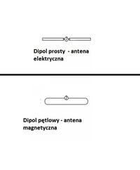
    I gave a picture of how I understand it.

    A simple dipole - an electric antenna - which receives the electric component of the electromagnetic field.

    A loop dipole - a magnetic antenna - which receives the magnetic component of the electromagnetic field.

    UNDERSTAND ?????
    ================================================== ==========
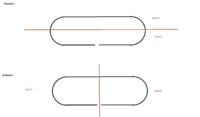
    Division of the loop dipole:

    Understanding Antenna Functionality: Comprehensive Explanation Beyond Wikipedia

    Which division does the loop dipole consist of? (given in the figure above)
  • #42 14936924
    _jta_
    Electronics specialist
    It depends on the distance of the wires in this loop - how close they are, it is an electric dipole, and how far - magnetic.
  • #43 14938446
    bombaatomowa2
    Level 14  
    and what is the specific distance range to know when is what antenna ??

    and what influences that how close is the electric antenna and how far is it magnetic - what does it depend on ??
    ===========
    more answer to the question from the second picture, please
  • #44 14942695
    _jta_
    Electronics specialist
    For a magnetic antenna, the area of the loop is important. For an electrical system, the length and distance is such as to obtain the required impedance.

    I don't know what you mean by that question. Can't you search for knowledge in a book? You're not going to tell me that there are no libraries in Gdańsk?

    Learn at least some basic concepts and knowledge and share what you already know - translating "from scratch" to someone who knows nothing would take several years.
  • #45 14943741
    bombaatomowa2
    Level 14  
    It is not Gdańsk (as I was setting up an account, I was in Gdańsk), now it is a place in Poland, far from culture and libraries.
    ===
    Another answer to the question from the second picture, please.
    ===

    Don't understand how the distance between two conductors can affect impedance?

    ===

    I do not understand why the antenna gain is given with a minus sign, e.g. -3dB.

    ===
    Is the signal strength / strength different from the wave amplitude ?? (at least that's how I understand it)
    For example, when the signal passes through an object (wall, glass), then the attenuation takes place, i.e. the signal amplitude is reduced, and therefore the signal strength / strength. Okay??

    =============
    Quote:

    The circular loop is a magnetic dipole; a loop in which two wires run close to each other, at the ends are connected, one of them is interrupted in the middle and there is a cable connected to the receiver / transmitter, it is an electric dipole - these are two electric dipoles next to each other acting as a 4-fold step-up transformer antenna impedance.


    My breakdown of your text:
    The circular loop is a magnetic dipole;

    https://pl.wikipedia.org/wiki/Antena_magnetyczna#/media/File:Schwarzbeck_HFRAE_5161.jpg The magnetic antenna must have circular loops, as in the picture from the link from Wikipedia

    A loop in which two wires run close to each other, at the ends are connected, one of them is interrupted in the middle and there is a cable connected to the receiver / transmitter, it is an electric dipole - these are two electric dipoles next to each other acting as a 4-fold step-up transformer antenna impedance.
    And the electric antenna has loops as if flat.

    So the magnetic antenna is a circular antenna and the electric one is in the shape of a flat loop.
    Okay??
    ==========================================

    He still wants to go back to coaxial cables.
    Does the use of a 50 Ohm cable in a certain installation have any advantages that one is used and the equipment is selected for it?
    And in another installation, the use of 75 Ohm has some other advantages, that just in this one must be a 75Ohm cable and the rest of the equipment is selected for it ??

    If there are any advantages and disadvantages I would like to know about them.

    Or maybe it would be possible to have the same cables with the same impedance everywhere and each equipment to be adapted to the same cable?

    I am very curious why there are so many types of cables and I am curious if it has a technical or economic aspect ??
  • #46 14945082
    _jta_
    Electronics specialist
    Another answer to the question from the second picture, please.

    But I don't understand what this question is about.


    Don't understand how the distance between two conductors can affect impedance?

    Affects the wave impedance. The farther they are (in relation to their thickness), the greater the impedance. This is due to the fact that impedance = ? (inductance / capacitance), and when they are next, the inductance increases (more space for the magnetic field) and the capacitance decreases (the electric field has to travel a greater distance).


    I do not understand why the antenna gain is given with a minus sign, e.g. -3dB.

    https://en.wikipedia.org/wiki/Antenna_gain - here the gain is positive if the antenna gives a greater signal than the electric dipole or the isotropic antenna; and depending on what is being compared with, either dBi (gain versus isotropic antenna) or dBd (gain versus dipole) is used.

    The circular loop is a magnetic dipole;
    https://pl.wikipedia.org/wiki/Antena_magnetyczna#/media/File:Schwarzbeck_HFRAE_5161.jpg The magnetic antenna must have circular loops, as in the picture from the link from Wikipedia


    It does not have to, you can make a frame (square, rectangle), ferrite (coil on a ferrite rod), slotted - there are many different designs. I don't know if the one in the photo is not a slotted one - this wheel has a bit without metal on top.


    And the electric antenna has loops as if flat.

    So the magnetic antenna is a circular antenna and the electric one is in the shape of a flat loop.
    Okay??


    Roughly yes. But there are many different antenna designs ...


    He still wants to go back to coaxial cables.
    Does the use of a 50 Ohm cable in a certain installation have any advantages that one is used and the equipment is selected for it?
    And in another installation, the use of 75 Ohm has some other advantages, that just in this one must be a 75Ohm cable and the rest of the equipment is selected for it ??


    A typical "electric dipole" (but not a loop) antenna has an impedance of about 75 ?, an electric loop dipole of 300 ? (and the balun allows this to convert to 75 ? ;) - that is why such impedances are convenient for antenna cables. But the satellite dish has a built-in converter and the cable is connected after the converter - and the cable does not have to be matched to the antenna, but to the converter - maybe converters are made that match the 50? impedance?

    50? coaxial cables are used in typical measuring equipment and in the Ethernet network (such as a concentrator - it is already out of fashion); but I saw 93 ? cables in measuring equipment in which there were high voltages and low currents.
  • #47 14953537
    bombaatomowa2
    Level 14  
    The antenna topic is quite difficult. But the division of antennas into electric and magnetic still bothers me. Let's say we have 2 antennas in front of us and how to visually determine whether a given antenna is electric or magnetic ???

    ==

    As for cables, you have explained, in relation to cables for a TV set, why 75 is used.
    For other cables, you only said where they are used, but I still do not know why coaxial cables with impedance other than 75 were created. Why is there a 75 ohm cable in the measuring equipment? For example, I have a 50 Ohm cable from the modem to the LTE antenna, but I don't know why it could not be 75 ohm.
    The point is, could it not be possible to make one standard 75 ohm cable for all installations?

    And this photo is https://pl.wikipedia.org/wiki/Antena_magnetyczna#/media/File:Schwarzbeck_HFRAE_5161.jpg is from https://pl.wikipedia.org/wiki/Antena_magnetyczna where it says that it is a magnetic antenna.

    ===
    The electric antenna receives the electric component / electric field and therefore current flows in the installation. And the magnetic antenna receives the magnetic component (magnetic field) and in this antenna, under the influence of this magnetic component, an electric field is created which only this electric field generates the current flow.
    So in such a magnetic antenna it is as if there is more to "work" to create a current flow.
    Do you understand well?
  • #48 14960059
    _jta_
    Electronics specialist
    Let's say we have 2 antennas in front of us and how to visually determine whether a given antenna is electric or magnetic ???
    Unfortunately, it is not that simple. You have to learn a lot and you can make a mistake. Can be measured by placing the antenna in a standing wave.


    Why can't there be a 75 ohm cable in the measuring equipment?
    The measuring device has a capacitance at the input. In order for this capacitance not to distort the measured signal, it has to be compensated - for example with a cable section of higher impedance. And it is easier, the lower the impedance the cable has - that's why it is better to have cables with 50? impedance than 75? for measuring equipment.


    The electric antenna receives the electric component / electric field and therefore current flows in the installation. And the magnetic antenna receives the magnetic component (magnetic field) and in this antenna, under the influence of this magnetic component, an electric field is created which only this electric field generates the current flow.
    So in such a magnetic antenna it is as if there is more to "work" to create a current flow.
    Do you understand well?


    Approximately. For example, a loop dipole contains a transformer and is therefore more complex than the simplest magnetic antenna. And for the generation of current in the antenna, an alternating electric or magnetic field is necessary.
  • #49 14961387
    Wirnick
    Level 30  
    bombaatomowa2 wrote:
    ===
    The electric antenna receives the electric component / electric field and therefore current flows in the installation. And the magnetic antenna receives the magnetic component (magnetic field) and in this antenna, under the influence of this magnetic component, an electric field is created which only this electric field generates the current flow.
    So in such a magnetic antenna it is as if there is more to "work" to create a current flow.
    Do you understand well?

    The "old school" of an electric antenna (a piece of a metal rod) said that it is a capacitor lining capable of polarizing in an electric field - look at the electroscope, where there is a potential difference from the head to the leaflets. The second facing is mass (it may be Earth). The alternating voltage of these facings supports the input voltage resonance circuit in resonance. The transmitting circuit must resonate with the receiving circuit as in a tuning fork.
    In the magnetic antenna, this voltage is induced in the coil.

Topic summary

The discussion revolves around the functionality of antennas, focusing on the distinction between electric and magnetic antennas. Participants explore how antennas convert electromagnetic waves into electrical signals and vice versa. Key points include the role of electric and magnetic fields in antenna operation, the concept of impedance, and the differences in design between electric dipoles (which respond to electric fields) and magnetic dipoles (which respond to magnetic fields). The conversation also touches on practical aspects such as coaxial cable impedance and the challenges of understanding antenna theory without advanced mathematical knowledge. Visual aids and analogies are suggested to clarify concepts, emphasizing the complexity of antenna functionality.
Summary generated by the language model.
ADVERTISEMENT