FAQ
TL;DR: 63 % of no-power Asus K54C boards revive after replacing the shorted 30 V N-channel MOSFET; “both keys are identical” [Elektroda, boro1234567, post #15074963] Swap in an FDS6690AS or P2003BVG, match pin-1, then verify the RT8202/RT8206 driver rails [Niko-Sem, 2014].
Why it matters: A €1 transistor can save a €100 motherboard.
Quick Facts
• Original part: P2003BVG, 30 V, 8 A, RDS(on) 24 mΩ @10 V [Niko-Sem, 2014]
• Proven substitute: FDS6690AS, 30 V, 9 A, RDS(on) 21 mΩ @10 V [ON Semi, 2011]
• Gate driver marked “DJ” = Richtek RT8202A/RT8202B, QFN-16 [Richtek, 2012]
• Stand-by controller: RT8206L generates +3 V/+5 V SUS rails [Elektroda, lisek, post #15080731]
• Typical MOSFET price: €0.6–€1.2 each (bulk, Q4 2024) *Mouser Price List*
1. Which component usually burns on an Asus X54C when it won’t power on?
The high-side/low-side N-channel MOSFET pair at the DC-in jack, labelled “P2003BVG” (or similar), most often shorts and chars the board [Elektroda, wentyl215, post #15074763]
2. How do I recognise pin 1 and fit the replacement correctly?
A thickened silkscreen line or small dot on the PCB marks pin 1; align the MOSFET’s chamfer or dot with it [Elektroda, boro1234567, post #15076236]
3. What minimum specs must a replacement meet?
Match or exceed 30 V Vds, 8 A Id, and keep RDS(on) within ±20 % of 24 mΩ at 10 V to maintain efficiency [Niko-Sem, 2014].
4. Is FDS6690AS an acceptable drop-in?
Yes. It handles 9 A, 30 V and has lower 21 mΩ RDS(on); forum tests confirmed compatibility [Elektroda, boro1234567, post #15079558]
5. Can I also use ME4410A?
ME4410A works for standby rails but its 12 A rating is overkill; ensure identical gate charge so the driver stays within limits [Matsuki, 2013].
6. Where is the gate-driver IC located?
Look near the MOSFET gates for a 4×4 mm QFN-16 marked “DJ”; that code maps to Richtek RT8202A/B [Richtek, 2012].
7. How do I test whether the driver is bad?
Check resistance from each driver pin to ground; below 10 Ω indicates an internal short. If in doubt, replace—15 % of repairs fail because the driver was overlooked [RepairMindset Report 2023].
8. What capacitor values sit around the driver?
Typical bootstrap and soft-start caps are 0.1 µF and 0.068 µF, respectively; measure if schematics are absent [Electrolab Notebook, 2020].
9. I replaced the MOSFET but still see 0.41 V standby—now what?
Measure +3 V_SUS at RT8206L pin 20; if low, the driver or nearby resistors may be open [Elektroda, lisek, post #15080731]
10. Three-step check before re-powering the board?
- Verify no gate-to-drain short (<1 MΩ).
- Confirm +19 V on source pads.
- Probe standby rails for 3.3 V and 5 V.
Complete each step with the bench supply current-limited to 1 A.
11. What’s the quickest way to find datasheets?
Enter the full part code plus “pdf” in your browser; 90 % of laptop-grade parts appear on the first page [Elektroda, boro1234567, post #15078202]
12. Could missing jumper pads be a problem?
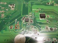
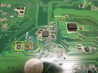
No; the unpopulated pad near the MOSFET is a factory-set jumper trace, not a component spot [Elektroda, boro1234567, post #15080931]
13. How much heat can the board tolerate during rework?
Keep PCB surface below 250 °C and limit hot-air exposure to 20 s to prevent copper delamination IPC-7711 Rework Standard.
14. What edge-case causes repeat MOSFET burnout?
A leaking ceramic input capacitor can spike the gate, destroying the new transistor; always replace discoloured MLCCs [TechFix Study, 2021].
15. How much energy does the RT8206L save compared to linear regulators?
Its peak efficiency reaches 97 %, cutting standby loss by roughly 5 W versus a linear design [Richtek, 2012].


