logo elektroda
logo elektroda
X
logo elektroda

Interesting connection of wires in a block made of a large board

Elektronik2013 150867 25
ADVERTISEMENT
Treść została przetłumaczona polish » english Zobacz oryginalną wersję tematu
  • #1 15086239
    Elektronik2013
    Level 11  
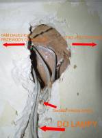
    Hello. I am renovating the toilet in an apartment in a prefabricated block. The block is from the end of the 1980s, 2-wire copper installation. After removing the wallpaper, I uncovered the lamp's power cord (it was on the wall) because now there will be lighting in the ceiling and I saw a rather interesting connection. Several different wires, a loop nailed down. The lamp is powered by two different wires with cut wires. In general, it is difficult to understand what is going where. I decided to run a new cable for toilet lighting from the switchboard and a new cable for the switch. I put this photo as a curiosity and ask how the lighting cables were distributed in the large panel. There are no drain wires from the switch or a wire for the lamp in the box beforehand. Tomorrow it will check back to the switch itself, maybe I'll come across something interesting again.
  • ADVERTISEMENT
  • #2 15086256
    elvis13
    Level 18  
    How will you implement shock protection?
  • ADVERTISEMENT
  • #3 15086258
    elpapiotr
    Electrician specialist
    You probably won't.
    One two-wire cable runs from the switchgear towards the lamp, one wire is cut there (lamp connection) and then to the switch that shortens both wires.

    There were several schools of conducting installations on a large disc, by the way.
  • #4 15086260
    opornik7
    Electrician specialist
    Elektronik2013 wrote:
    and I ask how the lighting wires were distributed in the large panel.

    For ceiling outlets in the neighbor's floor on the upper floor.
  • #5 15086288
    Elektronik2013
    Level 11  
    elvis13 wrote:
    How will you implement shock protection?


    New 3x1.5mm dam cable. 10A char B protection and residual current device. The grid layout is TN-C. I put the protective conductor on the PEN rail and the L and N through the differential.
  • #6 15086309
    elvis13
    Level 18  
    In which zone in the bathroom is the luminaire?
    Elektronik2013 wrote:
    I decided to run a new cable for toilet lighting from the switchboard and a new cable for the switch.

    You're doing repairs, tell me what about the sockets?
  • #7 15086452
    Elektronik2013
    Level 11  
    @ elvis13 , 2 LEDs in the ceiling + lamp above the mirror

    The socket is located 70 cm from the washbasin, next to the mirror. The socket, of course, with earthing and a flap. It will rarely be used because it is also in the bathroom and there is a washing machine, dryer etc. connected. This room is a toilet so one single socket is enough, I think it will be fully enough. When the bathroom is occupied, it will be possible to connect the aforementioned dryer.
    Cable to the socket 3x2.5mm, fuse 16A.
  • #8 15086516
    elpapiotr
    Electrician specialist
    What about the RCD for this socket? Will be ?
  • #9 15086542
    Elektronik2013
    Level 11  
    @elpapiotr Yes

    I try to do everything as correctly as possible, after all, renovation is done for many years. I was still thinking about an additional equalizing connection of the tap and the flush pipe, but I think I'll let it go. I do not know much about it, and they are made in the basement of the block of flats, so I will rather leave it alone.
  • ADVERTISEMENT
  • #10 15086560
    opornik7
    Electrician specialist
    Elektronik2013 wrote:
    I was still thinking about an additional equalizing connection of the tap and the flush pipe, but I think I'll let it go.

    I'm getting off this bus. :( He's not coming my way.
    Elektronik2013 wrote:
    I don't know much about it

    And here is the dog buried. Are you going to have appendix surgery in a few days? Good luck.
  • #11 15086574
    Elektronik2013
    Level 11  
    @ resistor7 I won't.
    I wrote that I do not know about equipotential bonding, so I will not use them, they are made in the basement of the block, so there is some additional protection.
  • #12 15086672
    CYRUS2
    Level 43  
    Elektronik2013 wrote:
    I was still thinking about an additional equalizing connection of the tap and the flush pipe, but I think I'll let it go.

    Good decision. If something shows up on this compensatory, you can damage organs.
  • #13 15086694
    zwrotnica
    Level 16  
    elpapiotr wrote:
    You probably won't.
    One two-wire cable runs from the switchgear towards the lamp, one wire is cut there (lamp connection) and then to the switch that shortens both wires.

    There were several schools of conducting installations on a large disc, by the way.

    This is probably not a real great album. In the reinforced concrete walls, there were already channels, pipes and boxes planned at the stage of production of such a slab.
    Wires with a nail went along the partition walls. If made of brick, then the "cobweb" was nailed to the wall in several places and then everything was covered with classic lime plaster, if it was made of plaster, it was nailed in grooved channels and then plastered. The construction of these wires provided for their direct nailing.
    Back then, people didn't play with the excess of junction boxes - they had to be done quickly (housing hunger) and it was only supposed to act :)

    And this cable is probably actually cut for a switch and a separate single one goes to the lamp with the switch. And you should be glad that copper was placed there, because often they used to be aluminum installations, i.e. an energy massacre at home.

    Added after 19 [minutes]:

    Elektronik2013 wrote:
    In general, it is difficult to understand what goes where

    In general, pay attention to the location of sockets, switches, and lamp cables protruding from the wall. In theory, cables should go the same height everywhere and perpendicular / parallel to the points. Theoretically :)

    If you had any " detector "It is best to use it to draw a schematic diagram of electric lines in the apartment. It is worth doing this so that when you hang your grandfather's portrait in a new place or install a shelf, you do not drill into the installation.
  • #14 15087301
    Elektronik2013
    Level 11  
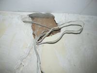
    @steering the block is made of a large panel, and this particular wall is a plaster partition wall. I chipped off a bit more and was still the loop seen in the photo below. Apparently they did it as he wrote @elpapiotr . I take pictures of the installation on an ongoing basis so that I know what is going on later.

    I will give you one more interesting fact, in another partition wall the wires for the switch were located in such a way that the side lugs stuck into the wire. The cord came out of the side of the can just where the paws are sticking.
    In a typical reinforced concrete slab wall in the kitchen, I saw wires in conduits, but interestingly, these conduits were only next to the boxes and sockets (so with 20cm). Replacing the cable in such a conduit was not possible because the cable was already in the wall under the plaster.

    Interesting connection of wires in a block made of a large board
  • #15 15093723
    zwrotnica
    Level 16  
    Elektronik2013 wrote:
    @steering the block is made of a large panel, and this particular wall is a plaster partition wall [/url]

    That's what I'm talking about!
    Make documentation as soon as possible because in a few years you will not find out what and who was up there before!

    There is one more thing worth considering. Since this is a communist bloc taken over by the Cooperative, for example, you go to the Management Board for ... issuing project documentation! Demand a copy and you will find "your" connections there instead of bothering people here unnecessarily :)
  • #16 15093729
    opornik7
    Electrician specialist
    zwrotnica wrote:
    Since this is a communist bloc taken over by the Cooperative, for example, then here go to the Management Board for a request for ... issuing project documentation! Demand a copy and you will find "your" connections there instead of bothering people here unnecessarily :) )

    Are you serious or for the balls? Documentation at the cooperative, good joke :D
  • #17 15100796
    elektronik123456789
    Level 22  
    No joke, but the truth. When I asked the cooperative to present the conditions for the installation of air conditioning, it was from such plans on large-format paper that they checked from the owners of whose apartments I need to obtain approval for the load capacity of the balcony. ...
  • #18 15152159
    zwrotnica
    Level 16  
    opornik7 wrote:
    zwrotnica wrote:
    Since this is a communist bloc taken over by the Cooperative, for example, then here go to the Management Board for a request for ... issuing project documentation! Demand a copy and you will find "your" connections there instead of bothering people here unnecessarily :) )

    Are you serious or for the balls? Documentation at the cooperative, good joke :D

    So where do you live, what kind of Cooperative is it? Report the case to the Prosecutor's Office if there is no construction documentation in the office of this Cooperative!
  • #19 15167294
    piciu.h
    Level 12  
    From what I can see, the wires are cut, not cut, so this is not connecting the wires, unless I see badly. In the will to explain, this is how you used to make bends on this type of pipes so that they did not stick out from the wall. It looked different, depending on the "specialist", from the level a 90-degree bend down, the veins were cut and turned into a square, and the ubiquitous nails to stick to the wall and plaster.
    And a great album is not like a colleague wrote earlier because who would hammer a nail? And the slab was not plastered (unless it is a different plot of land).
  • #20 15167410
    Łukasz-O
    Admin of electroenergetics
    piciu.h wrote:
    From what I can see, the wires are cut, not cut, so this is not connecting the wires, unless I see badly. In the will to explain, this is how you used to make bends on this type of pipes so that they did not stick out from the wall. It looked different, depending on the "specialist", from the level a 90-degree bend down, the veins were cut and turned into a square, and the ubiquitous nails to stick to the wall and plaster.
    And a great album is not like a colleague wrote earlier because who would hammer a nail? And the slab was not plastered (unless it is a different plot of land).

    After all, you can clearly see that it is a partition wall made of cardboard and gypsum board.
    The concrete slabs were also nailed, special nails were used - mainly shot in, they were also attached to building gypsum.
    Interesting connection of wires in a block made of a large board

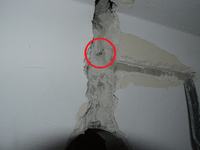
    Wires were cut at the bends, but not only. It was common practice to cut the veins in order not to make unnecessary lighting junction boxes or bells. The excess of the (neutral) conductor was pushed into expansion joints or technical openings in the slabs, commonly known as "garami" by the builders.
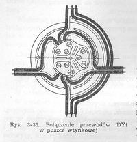
    If they had to give a can, they only put the necessary wires into it, the rest was led sideways:
    Interesting connection of wires in a block made of a large board
    All this to make the box as thin as possible and fit into the plaster.
    Of course, as in every area of life, there were exceptions to every rule ;)

    In spite of everything, the boards were plastered, and often only a putty (depending on the system and years of construction) was used on the ceiling, which sometimes could fall off in whole sheets.
    A friend once came back from school, entered the bathroom and the whole "ceiling" was on the ground :D
  • ADVERTISEMENT
  • #21 15167585
    piciu.h
    Level 12  
    Don't be upset Lukaszu-O! Big plate versus big plate, techniques in those days when it comes to electrics and other fields are far from even today's accepted standards. Back then, the only standard that existed was that it would work and be done quickly. And since the need is the mother of invention, and the methods have evolved, it was faster to squeeze the excess into the "pots" than to struggle with the can. Well, buddy, you are right, but I am too. ?
  • #22 15167911
    Łukasz-O
    Admin of electroenergetics
    piciu.h wrote:
    Don't be upset Lukaszu-O! Big plate versus big plate, techniques in those days when it comes to electrics and other fields are far from even today's accepted standards. Back then, the only standard that existed was that it would work and be done quickly. And since the need is the mother of invention, and the methods have evolved, it was faster to squeeze the excess into the "pots" than to struggle with the can. So, buddy, you are right, but I am too. ?

    But I am far from nervous, I am a very calm person :D

    After all, I wrote:
    Łukasz-O wrote:
    Of course, as in every area of life, there were exceptions to every rule ;)
  • #23 16747348
    PPK
    Level 29  
    The old one was a surveillance inspector back then. This type of installation was called the Workers 'and Peasants' Installation. They were supposed to save so ..... they stole. After 20 years (renovation), a friend found ... a cotton wool cloth from the gap between the plates.
  • #24 16747375
    elpapiotr
    Electrician specialist
    PPK wrote:
    The old one was a surveillance inspector back then. This type of installation was called the Workers 'and Peasants' Installation. They were supposed to save so ..... they stole. After 20 years (renovation), a friend found ... a cotton wool cloth from the gap between the plates.

    Very old ? :cunning:
  • #25 16747536
    PPK
    Level 29  
    Very...... :) . Unfortunately, in that better world.
  • #26 16747833
    kozi966
    Moderator of Electricians group
    Last post was visible ....
    Quote:
    20 Nov 2015 13:34


    We don't refresh the cutlets!
    I close.

Topic summary

The discussion revolves around the complexities of electrical wiring in a prefabricated apartment block from the 1980s, specifically concerning a two-wire copper installation. The original poster discovered an unusual wiring configuration while renovating a toilet, where multiple wires were cut and connected in a loop, complicating the understanding of their distribution. Participants shared insights on shock protection, the importance of proper wiring practices, and the historical context of electrical installations in such buildings. Recommendations included using a new 3x1.5mm cable with appropriate circuit protection and considering the placement of sockets and lighting fixtures in relation to safety standards. The conversation also touched on the challenges of documenting existing wiring and the potential for discovering outdated or unsafe practices in older installations.
Summary generated by the language model.
ADVERTISEMENT