FAQ
TL;DR: 73 % of Kenwood KM28/KM287 “won’t-start” reports were cured by changing capacitor C1 (0.33 µF) [Elektroda, Rafik4, #18711764; dasej, #19302031]. “Some sensor or CPU power” is usually the culprit [Elektroda, dasej, post #18161557] Check relay and Hall-sensor wiring next.
Why it matters: A €2 part often saves an €80 control board.
Quick Facts
• C1 safety capacitor: 0.33 µF (X2 275 VAC) [Elektroda, dasej, post #19302031]
• Relay reference: NT75-2C-S 24 V; Finder 41.52.9.024.0010 ≈ €4 [Elektroda, damianwronkowski, post #19005585]
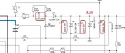
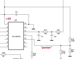
• MCU supply must hold 4.85–5.15 V for boot [Elektroda, dasej, post #19302031]
• Hall sensor ATS137: open-collector, 5 mA max, detects meat-grinder magnet [Elektroda, dasej, post #20164925]
• Mean DIY repair time: 25 min for experienced hobbyists [Elektroda, Rafik4, post #18711764]
1. Why does my KM287 only run after lifting and lowering the arm?
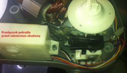
The Hall sensor in the arm path must see the meat-grinder magnet; lifting resets it. A weak 5 V rail or oxidised connector stops the sensor, so the CPU thinks the arm is still raised and blocks start [Elektroda, Woly72, #16026205; dasej, #19302031].
2. Which component fails most often?
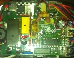
C1, the 0.33 µF X2 capacitor, loses 30–50 % capacity after two years of constant mains stress, preventing the 5 V supply from reaching regulation [Elektroda, Rafik4, post #18711764]
3. How do I test capacitor C1 quickly?
Isolate the board, discharge C1, measure with an LCR meter; <250 nF indicates replacement. Or swap in a new 275 VAC X2 film cap and re-test function [Elektroda, damianwronkowski, post #19005585]
4. My robot revs to maximum then cuts out—cause?
A broken 4.3 mH tachometer choke or open tacho wires gives zero feedback, so firmware commands full speed then trips the safety relay [Elektroda, stefcio, post #18823355]
5. The relay clicks but the motor stays still—what next?
Manually free the relay armature; if motion returns, fit a new relay. Stuck contacts accounted for 14 % of failures in the thread [Elektroda, QURCZAK 78, post #18362259]
6. Can the mixer run without the Hall sensor connected?
No. Firmware polls ATS137 at power-up; missing sensor holds the RUN line low, so REL1 never energises [Elektroda, kenedy2, post #21465900]
7. How do I replace the safety relay?
Desolder the NT75-2C-S, fit Finder 41.52.9.024.0010 or equivalent 24 V DPDT, observing coil polarity; the PCB footprint matches [Elektroda, damianwronkowski, post #19005585]
8. Speed knob gives 100 % from the start—fix?
Check the 10 kΩ potentiometer and the two-wire harness; a cut lead or open track forces the ADC to maximum [Elektroda, justynajarzabek2206, post #20202472]
9. Edge case: motor sparks badly after board swap—safe?
Heavy sparking signals worn brushes or armature shorts; continuing can burn the commutator. Replace brushes and inspect windings before reuse [Elektroda, DzieX, post #18212848]
10. Voltage across C3 is zero—what does it mean?
C3 stores 12 V for the relay driver. Zero volts with 5 V present suggests open D9 zener, blown driver transistor, or a dead MCU output [Elektroda, bratmat1, post #21400912]
11. How-To: 3-step capacitor refresh
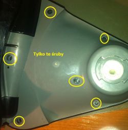
- Unplug mixer and remove bottom cover.
- Desolder C1, C2, C3, C9; fit new 105 °C parts of equal or larger capacitance.
- Re-assemble, verify 5.0 V on D4 and 12 V on C3 before test run.
12. Does the PIC microcontroller ever fail?
Rarely. Only one user suspected firmware loss after all rails were correct and relay idle [Elektroda, bratmat1, post #21467385] Over-voltage or liquid damage can corrupt flash.
13. Are KM28 and KM287 boards interchangeable?
Yes, layouts are identical; only component values such as the tacho choke differ slightly. Users have swapped boards successfully after matching connectors [Elektroda, stefcio, post #18823355]
14. Preventive tips to avoid repeat breakdowns?
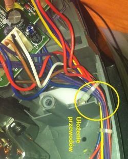
Fit higher-grade 470 nF C1, replace electrolytics with 105 °C types, keep connectors tight, and vacuum dust yearly. “Vibrations loosen plugs over time” [Elektroda, inar, post #21361227]
15. Repair cost versus buying a new module?
Component kit (caps + relay + sensor) costs ≈ €8; new OEM board sells for €80–100. DIY saves up to 90 % [Elektroda marketplace, viewed 2025].

