logo elektroda
logo elektroda
X
logo elektroda

Pioneer X-HM72 Repair: ON LED Flashing, Dark Screen, Key Combinations Ineffective, Voltage Issues

choleszek 18954 25
ADVERTISEMENT
Treść została przetłumaczona polish » english Zobacz oryginalną wersję tematu
  • #1 17056610
    choleszek
    Level 10  
    Hello forum members.
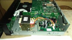
    I have a tower in repair as in the topic. The equipment does not work, the screen is dark, the ON LED flashes continuously after switching on. Pressing the key combination STANBY / ON + STOP and INPUT + SkipUp does not do much. The use of the first combination when applying the mains voltage causes the red TIMER diode to flash and the blue diode is constantly on. The second key combination does nothing.
    After turning on, you can hear the relays and you can see a slight rotation of the CD.
    The switching power supply seems to be working. It gives the voltage of 3.3 V, 15 V and about 40 V instead of 22 V. The latter is the voltage for the LCD backlight, and since the display does not work, such a higher voltage is probably correct.
    I went through the whole NO POWER algorithm - without success.
    1. Voltage on C681 3.3 V
    2. Waveforms 16 exactly as shown in the picture
    3. Waveforms 11 also as shown in the drawing
    4. Security checking gives the exact opposite states than in the algorithm
    PWM Protection 3.2V
    DC Protection 3.2V
    AMP Protection 0V
    POWER Protection 3.2V
    Over Temperature Protection 2.5 V and 2.5 V
    When the red Timer LED is flashing, the voltages are the same.
    If this is not a protected operation, what is the fault? I'm out of ideas.
    By the way, I provide extensive excerpts from the X-HM72 X-HM82 service, obtained commercially and so far unavailable on the web.
    Attachments:
  • ADVERTISEMENT
  • #2 17057521
    SERVICE-AV
    Level 39  
    In the manual you have included, there are relevant information on the area of the errors. Time to measure the times :)
  • #3 17057588
    choleszek
    Level 10  
    You probably mean the times of lighting and non-lighting of the diode. Of course, I have already researched this. This is 500 out of 500 msec and suggests POWER Protection is working. However, this is not the case, as I wrote before, the voltage on the 12 PIN CP307 for the POWER Protection security test is High 3.2 V. :(

    Added after 6 [hours] 22 [minutes]:

    Supplement. The time 500 msec / 500 msec refers to the state when the red Timer diode is flashing. When only the blue ON LED is flashing, the times are 1 sec / 1 sec. I checked the power supply voltage on the Main board in two states, from which POWER protect works. They are valid +30 -30, +5 -5 and +12.2 V and -11.8 V.
  • ADVERTISEMENT
  • #4 17061798
    wiatr1
    Level 12  
    I don't have the entire manual for this Pioneer, but on page 21 of this manual, what you gave up, you have the Power Protection security chip drawn up.
    The processor detects the power protection when pin4 of IC609 changes state from H-> L (check the voltage on pin4).
    You can deactivate it by desoldering the D334 diode (for a short time for the test).
    You have voltages of +12.2 V and -11.8 V, their sum does not give 0 V, which may cause a change of state from H-> L (opening of transistors Q336 or Q337).
    To check:
    - elements of the security system
    - supply voltages are not equal to +12.2 V and -11.8V, their sum does not give 0V
    - M3V3 SW voltage across the R660 resistor.
  • #5 17066181
    choleszek
    Level 10  
    Thanks for showing interest. The voltage on pin4 of IC609 is H 3.2 V. Power Protection is not active. The voltage on the M3V3 SW is correct at 3.2 V.
  • #6 17066251
    wiatr1
    Level 12  
    There are also DC and PWM protections that block the device from turning on, if it's not Power Protection.
    I have SM from Pioneer X-HM71-81 different boards, but the design is very similar.
    In case of activation of two protections due to a fault, the blinking of the blue LED may not be consistent with the table.
    To check:
    - levels from other security features on IC609
    - power amplifiers or not hot.

    If you can, then share the rest of the SM from the X-HM72, it would be easier.
  • ADVERTISEMENT
  • #7 17066289
    choleszek
    Level 10  
    I researched a few runs on the DMAIN disc. 11,12,16,14,17,15,31,32 are correct.
    Waveform 28 is wrong. I only get noise with an amplitude of + -0.2V. Perhaps it is due to holding the lock on the display.
    Mileage 13 is also not valid, they are SUB_CLK_IN and SUB_CLK_OUT on IC609. It is true that I could not test it on the IC609 pins, but on the XTAL601 quartz feet. While the OUT output is similar in frequency and voltage to the pattern, the IN waveform is completely different. Could this mean that the quartz is damaged? I have no experience with these elements.
  • #8 17066397
    choleszek
    Level 10  
    I checked the security states according to the algorithm on page 16 at the very beginning.

    "Security checking gives the exact opposite states than in the algorithm
    PWM Protection 3.2V
    DC Protection 3.2V
    AMP Protection 0V
    POWER Protection 3.2V
    Over Temperature Protection 2.5 V and 2.5 V
    While the red Timer LED is flashing, the voltages are the same. "

    It is true that not on the pins of IC609, but on the connectors. The resulting voltages suggest that there is no active protection.

    Complete SM attached.
  • #9 17066656
    wiatr1
    Level 12  
    In fact, this waveform on IN pin 10 suggests that there is something wrong - it does not wake up.
    If you have even a similar quartz, try to replace only solder briefly, because quartz do not like heating.
    check the pieces around the quartz and give the runs.
    In about 1.5 weeks I will have this Pioneer on the website (it comes to me after the purchase), then I will be able to compare this mileage.
    One more thing, did you try to cancel the switch-on interlock in accordance with point 5 on page 30 SM?
  • ADVERTISEMENT
  • #10 17068645
    choleszek
    Level 10  
    Yes, I tried to cancel the lock according to point 5 page 30 SM. These key combinations only work for me after unplugging and plugging in the power cord. And so STOP + Standby ON causes switching on and continuous lighting of the blue diode ON and flashing 500/500 msec of the red diode Timer. According to SM, it should be Protect Check mode. Attempting to press FF and Play repeatedly according to point 6.2 gives nothing (I work in the dark because the display is dark).
    In turn, the combination of FF + INPUT causes the switching on and blinking of the blue 1s / 1s LED.

    Correction of the 13th wave is correct, I have badly examined the quartz resonator with the oscilloscope. I didn't know it was such a sensitive element.
    First of all, there cannot be any extension cables - we touch the feet directly.
    Secondly, you need to test both legs at once (testing a single OUT leg gives the mileage, but testing a single leg IN extends the mileage).
    Third, first touch the leg from OUT, then add from IN (the reverse order turns off the generator).
    Of course, a different oscilloscope may behave differently.
  • #11 17068915
    wiatr1
    Level 12  
    If the quartz works, let's go back to run 28 (proc, memory batch damaged?)
    You have incorrect mileage 28 - i.e. dark display (is it not damaged?)
    Check the supply voltage to the LCD, diagram page 80 SM FPC102 pin 4.10 and BACKLIGHT_CTL control pin 3.7 should be H status acc. pattern.
    Check the voltage on IC5 pin 75, after turning on the power, it should set the state H (LCD backlight control).
    In my opinion, after turning on the power, the LCD should be slightly illuminated at least for a short while.
    You can briefly check the LCD backlight, give the H state through the resistor on the Q100 base, diagram page 80 SM and see how the LCD behaves (because maybe it displays something, but you can't see it).
  • #12 17121244
    choleszek
    Level 10  
    The supply voltage for the display on the FCP102 pin 4 connector is 35 V. I checked it on the basis of Q107, there is nothing like on the FCP102 connector. There is 34.3 V on the collector and emitter Q107. The higher voltage is explained by the lack of load. There is 3 V on pin10 of the FCP102 connector. However, on BACKLIGHT_CTL there is still 0 V. IC5 pin 75 does not display H.
    I gave the H state through the resistor on the Q100 base, the screen only lit when the power cord was connected. Only the backlight was on. Turning the device on with the STANBY / ON button turns off the screen and the voltage on the Q100 base drops to several hundred mV. So IC5 pin 75 stubbornly exposes L instead of H to control the LCD backlight. Looks like the display is good. I will try to investigate IC5 in more detail.
  • #13 17131721
    wiatr1
    Level 12  
    Pioneer X-HM72 Repair: ON LED Flashing, Dark Screen, Key Combinations Ineffective, Voltage Issues Pioneer X-HM72 Repair: ON LED Flashing, Dark Screen, Key Combinations Ineffective, Voltage Issues Pioneer X-HM72 Repair: ON LED Flashing, Dark Screen, Key Combinations Ineffective, Voltage Issues Pioneer X-HM72 Repair: ON LED Flashing, Dark Screen, Key Combinations Ineffective, Voltage Issues

    I already have this Pionier on the site. I have / had a damage in the SMPS standby power supply module.
    I pre-fixed it on a spider for inspection, and it went off. I am now waiting for the delivery of original parts, which I will eventually deliver there.
    I measured you the voltages on the SMPS power supply.
    You quote "on the FCP102 pin 4 connector is 35 V [...] I explain the higher voltage with no load."
    You have something wrong here !! - this voltage goes directly from the SMPS power supply as 22 V, so it is described in the diagram.
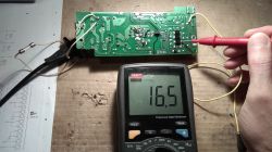
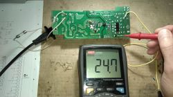
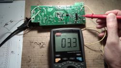
    For me, you have photos on the unloaded one taken out of the device
    22 V is 24.7 V measured behind the diode D221 (check D221 and the capacitors on this voltage)
    15 V is 16.5 V measured behind the D222 diode
    3.3 V is 3.3 V measured behind the D223 diode

    The Pioneer boot launch procedure is lengthy
    After a short press of STANBY / ON, after a while the relay will click, the blue diode starts flashing and it continues - initialization.
    For the first 10-11 seconds, the display is dimmed, which is as you wrote the quote "So IC5 pin 75 stubbornly exposes L instead of H to control the LCD backlight".
    Only after this time, the backlight goes to the display and starts showing the last function set before switching off.
    The blue diode, after LCD initialization, flashes a few more times and changes to continuous light. Pioneer has taken off - it works.

    Summing up, I would leave IC5 alone for now, check the power supply, because you have a few LDO regulators / voltage stabilizers in the diagrams, maybe one is missing.
  • #14 17132319
    choleszek
    Level 10  
    This difference in voltage from the SMPS power supply intrigued me.
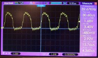
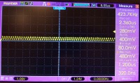
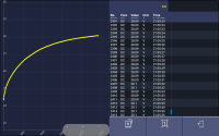
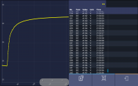
    I took out the power supply and took the measurements. At first I also had a little more than 24 V at the output after D221. After about 20 minutes, the voltage increases to just over 28 volts (screenshot 1). After this time, the voltage at the output of the 15 V line is also higher and amounts to 19 V.
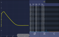
    After inserting the power supply into the device and connecting the power supply, the voltage on the 22 V line increases to 42 V (screenshot 2). During this time, the voltage on the 15 V line is 14.5 V.
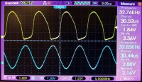
    After turning on Stanby / ON, the voltage on the 22 V line drops to 29.5 V after 20 minutes and remains more or less like this (Screenshot 3). There is 14.5V on line 15 all the time.
    He sees these differences due to the influence of the load on the 15 V line on the 22 V line, they are on the one hand, sometimes it is unloaded, sometimes it is.
    Thanks for the info on voltages and the boot process. I have checked a lot of supply voltages on main and dmain, but I will look at it again.
  • #15 17133881
    wiatr1
    Level 12  
    Quote
    "After inserting the power supply into the device and connecting the power supply, the voltage on the 22 V line increases up to 42 V"
    You have to explain it because I continue to say that it is very incorrect.
    First, replace the C805 (47u / 400V) and C823 (47u / 50V) capacitors in the SMPS power supply to know that the converter works stably.
    Next
    See you have different grounds in digital and analog circuits.
    Look at the diagrams.
    The grounds are connected to each other through 0R resistors or coils that are in series in the ground paths.
    Check these transitions, because such a voltage boost comes from somewhere - the voltage is added. If the CPU also sees a difference in potentials, it won't initialize the device.

    One more thing, is this Pioneer not time after, for example, an atmospheric discharge?
  • #16 17166908
    choleszek
    Level 10  
    I replaced the capacitors in SMPS C805, C823 and additionally C221 and C222. The inverter behaves the same as before the capacitor replacement. I checked a lot of resistors and coils connecting the ground, maybe all of them. There were a lot of them. They all led the way.
    I do not know if the equipment is after a lightning strike. It came to me damaged. There was no voltage from the SMPS converter. In this system, I also replaced D222, D226, D223, D224, R823, D824, D823, R824, R825, IC821 early.
  • #17 17178375
    gapulek1
    Level 2  
    Buddy, there are 2 DC voltage regulators 1.2 V and 1.9 V on the DMain board. There are smd capacitors C254 and C263 on the output - they are probably short-circuited. Hope this will solve your problem.
  • #18 17184559
    choleszek
    Level 10  
    Unfortunately, the capacitors are not short-circuited and the output voltages of the DC regulators, capacitors C207 and C206 are correct, 1.2 V and 1.9 V respectively.
  • #19 17185301
    gapulek1
    Level 2  
    There are only a few common damage specific to this hardware. The main damage is the SMPS ASSY board - most often one of the D222 and D226 diodes (SS315, Schottky diode in the 15 V line) is short-circuited, major damage to the converter is less frequent. A short circuit on 1.2V and 1.9V power lines is very rare, but the effects are exactly the same as yours. Device initialization does not take place properly, the control system blocks the display backlight, and the 22 V power line is not loaded and therefore its voltage increases even to 50 V. You must check all the voltages that are controlled by the control system, because you probably have a fault here. I have repaired this equipment from 10 pieces and I only had such damage as described.
  • #20 17193617
    choleszek
    Level 10  
    I checked the resistance of the dmain board after removing it from the system on the 3V3 power line and ground. It was frighteningly short, only 8 Ohm. After disassembling the CX870 WiFi module, the resistance increased to more than 2 k?. So the fault is in the CX870 module.
    I put in a replacement in the form of an identical module but with Pioneer NP01 - the equipment started. Unfortunately, the software of the module with NP01 does not include radio, CD and amplifier support, so the control and what could be seen on the display were limited. By the way, I wonder why Pioneer puts so much hardware functionality into the Lite-On CX870 module, the diagram of which is not even included in the service manual.
    After removing the screens from the damaged CX870 module, visual inspection did not reveal any charred elements. However, I noticed that the DM870A processor gets very hot. Most likely he is damaged. It is in a BGA casing and its replacement will not be easy. I searched the internet and found no way to buy a CX870 module with software for the X-HM72.
  • #21 17387289
    choleszek
    Level 10  
    Unfortunately, the repair of the CX870 module was unsuccessful. I will definitely buy the CX870 module programmed for the X-HM72.
  • #22 17673634
    manek33
    Level 14  
    Did you manage to buy this module?
  • #23 17673680
    griszka77
    Level 12  
    Not every blinking LED indicates a CPU failure, it could be a corrupt NAND and bad sector on it.
  • #24 17674679
    choleszek
    Level 10  
    manek33 wrote:
    Did you manage to buy this module?

    Yes, I did.

    griszka77 wrote:
    Not every blinking LED indicates a CPU failure, it could be a corrupt NAND and bad sector on it

    In my case, the processor was very hot, could NAND damage cause this effect?
  • #25 17674684
    griszka77
    Level 12  
    And can you read the contents of the flash or have you read it?
  • #26 17674865
    choleszek
    Level 10  
    Unfortunately I do not have.

Topic summary

The discussion revolves around troubleshooting a Pioneer X-HM72 audio system that exhibits a dark screen and a continuously flashing ON LED. The user reports ineffective key combinations for resetting the device and notes abnormal voltage readings from the switching power supply, particularly a higher than expected voltage for the LCD backlight. Various forum members suggest checking the power protection circuits, verifying the voltages on critical components, and examining the quartz oscillator for potential damage. The user identifies issues with the CX870 WiFi module, which appears to be faulty, leading to device initialization problems. Despite attempts to replace components and troubleshoot, the user ultimately concludes that the CX870 module needs replacement for full functionality.
Summary generated by the language model.
ADVERTISEMENT