logo elektroda
logo elektroda
X
logo elektroda

Single-Family House TNC Mains System: Understanding Voltage between L & PE in 3 Switchboards Setup

Albercik 321 28854 27
ADVERTISEMENT
Treść została przetłumaczona polish » english Zobacz oryginalną wersję tematu
  • #1 16035566
    Albercik 321
    Level 25  
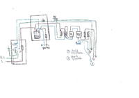
    Welcome. Single-family house, ground floor and attic. TNC mains system, single-phase. There are three switchboards - one main, outside the building with 25A main protection, the second one on the ground floor, which supplies the ground floor, and the third one, in the attic, supplies the attic. The main switchboard has a separation of PEN into PE and N. Measurement of the earth connection over 6 ?. There is one energy meter in the switchgear on the ground floor, from which the ground floor and the attic are measured. There is a 3x10mm cable from the main switchgear to the switchgear on the ground floor. The same goes from the switchboard on the ground floor to the switchboard in the attic. There is no PE conductor on the ground floor, only L and N. In the attic there are all three - PE, N and L. The installation is freshly installed. The PE conductor in the switchgear on the ground floor is connected by a strip with a PE conductor which goes to the attic. It is not distributed on the ground floor.
    As it turned out, in the attic there is a voltage of 0.88V between N and PE, while between L and PE there is a voltage of 97 - 100V. L and N are normally 230V with a penny. Interestingly, after connecting the light bulb in the kitchen to the L and N wires, without PE, the differential breaks down from time to time. And what's more interesting, it crashes both the kitchen and the rooms. Not alternately, but sometimes he taps one and sometimes the other. The circuit of the differentials in the attic distribution board is connected correctly, no blue wire is confused between the differentials. All PE conductors are connected to one strip and no PE is connected anywhere with N. At least in the attic.
    What's the problem? I mean something, but I'll wait for what you tell me.
    I'm sorry that I am describing this installation, but at the moment I have no way of making a scan of the installation to post a schematic on the forum.
  • ADVERTISEMENT
  • #2 16035590
    CYRUS2
    Level 43  
    Albercik 321 wrote:
    Installation freshly laid.
    Report a complaint to the person who made the installation.
    Installation diagnostics need to be done - on site. A good specialist is needed for this.
    You must first "figure out" this installation.
    Or else you have to pay for it.
  • #3 16035623
    kosmos99
    Level 38  
    There aren't any wires drilled through, maybe a peg is stuck between the wires.
  • Helpful post
    #4 16035655
    elpapiotr
    Electrician specialist
    The answer is here:
    Albercik321 wrote:
    There is no PE conductor on the ground floor, only L and N. In the attic there are all three - PE, N and L. The installation is freshly installed. The PE conductor in the switchgear on the ground floor is connected by a strip with a PE conductor which goes to the attic .

    But
    Albercik321 wrote:
    There is a flight from the main switchboard to the switchboard on the ground floor cable 3x10mm . The same goes from the switchboard on the ground floor to the switchboard in the attic. There is no PE conductor on the ground floor , there is only L and N

    PE is in the air, I suppose.
  • #5 16035670
    Strumien swiadomosci swia
    Level 43  
    Albercik 321 wrote:
    As it turned out, in the attic there is a voltage of 0.88V between N and PE, while between L and PE there is a voltage of 97 - 100V.


    First, check PE and N continuity, maybe you have no protection at all. Secondly, make a manual diagram, take a photo and paste it.
  • #6 16036107
    popiol667
    Level 18  
    1. There may be a slight difference in potential between the N and PE conductors - current flows through N and a voltage drop is deposited - whether 0.88V is a lot or little - I do not know, let more experienced colleagues comment.

    2. If the PE conductor hangs in the air and, for example, a computer with a switching power supply is plugged into the socket, then about 1/2 of the mains voltage is actually deposited on the PE conductor (the switch of the switch power supply filter forms a voltage divider, the center of which is connected to the housing and PE ).

    A similar situation occurs when, for example, you connect the computer to a socket without a protective pin - on the housing you have a potential of half the supply voltage in relation to the N wire.
  • #7 16037279
    Albercik 321
    Level 25  
    The electrician who did it, unfortunately, is dead (heart attack). This morning I was there and made a hand-drawn diagram of what I found. The schematic is not worthy of an electrician, it's a drawing, but I only had a pen on hand and I quickly corrected the colors with a marker pen, so I'm sorry for that. But that's how it is in any case connected and you can see what and how, and that's the most important thing. Single-Family House TNC Mains System: Understanding Voltage between L & PE in 3 Switchboards Setup At first glance, I don't see anything wrong with this installation. Most of the sockets, switches and switches are still not connected at all - the wires are in boxes, nothing touches each other anywhere - none of the wires are stripped of insulation, the wires are not in contact with each other. Measurement between PE and L in the kitchen gives 78V. In room 54V, in bedroom 69V. There is 232V between L and N.
    Could B + C let it pass?
  • #8 16037353
    elpapiotr
    Electrician specialist
    Buddy, take some load (e.g. a regular light bulb) and connect it to L-PE in front of the differential, while measuring the voltage.
  • ADVERTISEMENT
  • #9 16037380
    jann111
    Level 33  
    Measure the voltage but also the IPZ on the ground floor between L-PE.
  • #10 16037381
    marian1981.02
    Unitra equipment specialist
    Albercik 321 wrote:
    Measurement between PE and L in the kitchen gives 78V. In room 54V, in bedroom 69V. There is 232V between L and N.
    But what's your problem? That there's some tension at all between L and PE? Is it too low? I would rather worry about the latter. After all, N and PE are the same, N runs through the differential, so there must be a full 230V between L and PE. That's right ?
  • #11 16037414
    kortyleski
    Level 43  
    Measuring an electrical installation with a multimeter is like flying into space on the New Year's Eve. Installation measurements are performed with dedicated meters. For this you also need to know how to measure and be able to interpret the results. Give the kumaty electrician some money. This is also what he eats for a cylinder at some holiday he needs.
  • #12 16037425
    marian1981.02
    Unitra equipment specialist
    kortyleski wrote:
    Installation measurements are performed with dedicated meters.
    Do not overdo it that an ordinary multimeter cannot correctly measure the AC voltage of 230V in the network.
  • #13 16037456
    jann111
    Level 33  
    Eh Albercik, this joint installation of yours is a lot of work .....
    You cannot do separation in the connector and then zeroing it on the ground floor from the dedicated N.
    I agree to call a repairman, but not a flasher, my friend of Cortes. ;)
  • #14 16037476
    Albercik 321
    Level 25  
    What if the TT island was made?
    Can the B + C protector "pass some voltage to the PE through its" malfunction "? Has anyone ever come across something like this?
    I am also thinking to do a measurement of the earth resistance, is it surely mentioned 6 ohms. Because it seems to me that the grounding of the split point is not doing the job. J.
    It is also possible to connect to the earthing of the distribution point to the water network. It is definitely made of steel pipes, and the waterworks there don't mind. I even have a journal from that year with their approval.
    I'm grasping at all possibilities now. I am also thinking of measuring the continuity of PE. It will be a bit of work with this and I wonder what to do first - continuity measurement, then IPZ, and if everything turns out ok, then what? Make the island of TT and check?
  • ADVERTISEMENT
  • Helpful post
    #15 16037515
    kkas12
    Level 43  
    There is no question of TT island within one building. This is a daydream.
    How is a lightning arrester to "pass"? Either it's operational or it's junk.
    And besides, it should rather be in the lower switchboard.
    The earthing resistance does not matter, because it will not be "better" than the metallic connection to the N point of the transformer.
    You should make the main grounding equipotential bonding in the building.

    Only the impedance measurement will show the fastest where the error was made in connecting the protective conductors. It is certain that it was committed.
    Or, you can use Paul's clue in post number 8.
  • #16 16037541
    Wawrzyniec
    Level 38  
    kortyleski wrote:
    Friend Marian, you cannot. And in principle, you can, but only in an efficient installation. And this one is clearly not working.
    Yes you can. Also in working order. You only need to know what you want to measure in this way and how to connect the multimeter, e.g.
    elpapiotr wrote:
    Buddy, take some load (e.g. a regular light bulb) and connect it to L-PE in front of the differential, while measuring the voltage.
    Such a measurement multimeter is correct and will do a lot.
  • #17 16037568
    jann111
    Level 33  
    Albercik 321 wrote:
    continuity measurement, then IPZ, and if everything turns out ok, then what?

    It will not come out OK, there are no miracles.
    There may be no bridge in the connector and the PE has a ground fault caused by zeroed receivers connected to the installation on the ground floor.
    Did you disconnect the bridge when measuring R grounding? Has it been plugged in again?
    Forget about the island because it may become ... uninhabited. :|
  • ADVERTISEMENT
  • #18 16037884
    Albercik 321
    Level 25  
    Different ideas come up, so let's start one by one:
    In the switchgear on the ground floor, the PE conductor is 100% connected - I checked it, otherwise I would not draw it.
    At the separation point there is a bridge between PE and N - as it is in the diagram.
    In general, everything that is on the diagram is in fact - I drew the diagram this morning according to what I found. The only thing that comes to mind at the moment is:
    - the PE conductor has a break somewhere in the cable itself. But the cable is new. However, anything is possible
    - ground resistance measurement was not done, and the 6 ohms are sucked from the finger. Unfortunately, I do not have a meter to check it
    - somewhere there is a peg stuck between the veins
    Take a look at the diagram again and see if it is all well connected. I looked and thought about it several times and in my opinion everything is ok.
  • #19 16037891
    jann111
    Level 33  
    Albercik 321 wrote:
    . I looked and thought about it several times and in my opinion everything is ok.

    And did you read post # 13? Got it?
    How much is IPZ L-PE on the ground floor?
  • #20 16037994
    Strumien swiadomosci swia
    Level 43  
    Albercik 321 wrote:
    the PE conductor has a break somewhere in the cable itself. But the cable is new. However, anything is possible


    Then measure it sequentially, from point to point.
    Albercik 321 wrote:
    earth resistance measurement was not done, and the 6 ohms are sucked from the finger. Unfortunately, I do not have a meter to check it


    Why do you need it anyway ?????
  • #21 16038421
    kj1
    Electrician specialist
    Albercik 321 wrote:
    jumper between PE and N

    Check the N and PE strips well. Sometimes they are divided and you cannot see where the division is.
  • #22 16038550
    Wawrzyniec
    Level 38  
    elpapiotr wrote:
    Buddy, take some load (e.g. a regular light bulb) and connect it to L-PE in front of the differential, while measuring the voltage.
    Do this in the attic switchboard and measure the voltage between N and PE in the same switchboard. Then, without disconnecting the bulb, go down to the ground floor and there, in the switchboard, measure the voltage between N and PE. If it is the same as in the attic switchgear, repeat the measurement in the main switchgear. This way, you will find out which section you have EP discontinuity on.
  • #23 16038567
    CYRUS2
    Level 43  
    Albercik 321 wrote:
    The electrician who did it, unfortunately, is dead (heart attack).
    The friend's house has been stretching on Elektroda since 2014.
    Theme: "Voltage between L and PE."
    Albercik 321 wrote:
    What if the TT island was made?
    It does not match the above-mentioned quote.
    Councils without an on-site inspection - without taking measurements are risky.
    In 2014, a colleague of Akrzy expressed his opinion.
  • #24 16038901
    kj1
    Electrician specialist
    kj1 wrote:
    Check the N and PE strips well. Sometimes they are divided and you cannot see where the division is.
    pawlik118 wrote:
    very factual answer ..
    only a licensed electrician flying into space will understand

    Single-Family House TNC Mains System: Understanding Voltage between L & PE in 3 Switchboards Setup

    It's about such a strip. Such a strip is usually divided into two parts. Unfortunately, this division is not visible. It is important that the PE is connected to the same part (or bridged).
    My friend pawlik118 is such an explanation sufficient for you?
  • #25 16044683
    Albercik 321
    Level 25  
    CYRUS2 wrote:
    Albercik 321 wrote:
    The electrician who did it, unfortunately, is dead (heart attack).
    The friend's house has been stretching on Elektroda since 2014.
    Theme: "Voltage between L and PE."

    But you came up with ... Read the topic carefully, then give your opinion. Two different cabins and two different things ....
    The case is quite interesting, and the solution will not take place until March / April next year.
  • #26 16044794
    jann111
    Level 33  
    Albercik 321 wrote:
    the solution will not take place until March / April next year.

    You have a lot of time to earn a meter which checks the parameters of the installation, a lot of time to deepen your knowledge, but also time to think about whether it is worth taking care of it yourself and not entrusting a person who will make a diagnosis in 10 minutes. Paradoxically, the diagnosis is made.
    Your choice. ;)
  • #27 16045253
    CYRUS2
    Level 43  
    jann111 wrote:
    You have a lot of time to earn a meter which checks the parameters of the installation
    It won't do anything because you have to be able to interpret the measurements.
    You need to know what to measure.
    jann111 wrote:
    Is it worth taking care of it yourself and not entrusting a person who will make a diagnosis in 10 minutes.
    The meter costs a lot of money, the electrician will take less, he will tell you what is wrong.
  • #28 16914142
    Albercik 321
    Level 25  
    The voltage between L and PE is 230V, which is the same as between L and N. Everywhere. I believe that it is ok and there is nothing to combine. Separation of PEN into N and PE for the attic is done ok. The ground connection is 6 ohms. Differentials release at the current indicated on them 10 and 30mA, so it's ok, and that's the most important thing. In addition, it turned out that in one of the rooms the earlier electrician connected the PE wire instead of N to the temporary bulb and, surprisingly, nothing happened and the bulb was on. It turned out that it was the same in the switchgear, because the N conductor was too short and the electrician connected it to PE instead of the PN strip. Thanks for the help

Topic summary

The discussion revolves around a single-family house with a TNC mains system and three switchboards. The main concern is the voltage measurement between the live (L) and protective earth (PE) conductors, particularly in the context of a newly installed electrical system. Users suggest performing continuity checks on the PE and N conductors, measuring the impedance, and ensuring proper connections in the switchboards. There are concerns about potential voltage differences due to improper grounding and the possibility of a break in the PE conductor. The author ultimately confirms that the voltage between L and PE is 230V, indicating proper separation of PEN into PE and N, and that the grounding resistance is acceptable at 6 ohms. The discussion highlights the importance of professional diagnostics and proper measurement techniques in electrical installations.
Summary generated by the language model.
ADVERTISEMENT