logo elektroda
logo elektroda
X
logo elektroda

[Solved] N and PE terminal rails - whether they should be connected (bridged)

Kolchoze 25170 39
ADVERTISEMENT
Treść została przetłumaczona polish » english Zobacz oryginalną wersję tematu
  • #1 17533590
    Kolchoze
    Level 10  
    I am not an electrician but I am very interested in this topic and if I understand the essence of electricity and security systems, who knows. I had to write about it because maybe my question will be child's play for electricians. Well, I noticed in the home switchboard that the neutral wires (blue) are connected to one strip and the PE wires (yellow and green) to the other strip, and then the two strips are connected (so called bridge). So is there any difference between one strip and the other? If so, what is the difference?
  • ADVERTISEMENT
  • #2 17533619
    DriverMSG
    Admin of Computers group
    In the case of the old electrical installation (two-wire), N and PE were connected in the sockets. It is possible that you have one, and only the switchboard is newer.
  • #3 17533624
    kkas12
    Level 43  
    The difference is that one of them is the N bus and the other is the PE bus. And they are connected because they both originate from the PEN vein. This is known as the "PEN split point / point". The PE rail should also be grounded.
  • #4 17533748
    Kolchoze
    Level 10  
    N and PE terminal rails - whether they should be connected (bridged) N and PE terminal rails - whether they should be connected (bridged)
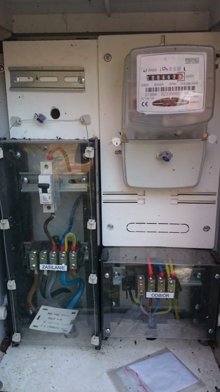
    Has the PEN separation been done in the meter cabinet?

    Added after 16 [minutes]:

    DriverMSG wrote:
    In the case of the old electrical installation (two-wire), N and PE were connected in the sockets. It is possible that you have one, and only the switchboard is newer.

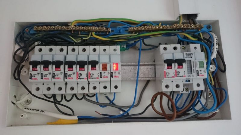
    The installation is new, maybe the photos from the meter cabinet (connections) and the home switchgear will help to answer the questions.
  • Helpful post
    #5 17533777
    elpapiotr
    Electrician specialist
    According to the photo on the right, with the meter, you can see this chapter (the right strip under the meter)

    I am surprised, however, that "black pudding" in the home security board.
    What is this, sorry?
    Since the new installation, where the RCD for socket circuits and lighting bathrooms ?
  • ADVERTISEMENT
  • #6 17533783
    Kolchoze
    Level 10  
    kkas12 wrote:
    The difference is that one of them is the N bus and the other is the PE bus. And they are connected because they both originate from the PEN vein. This is known as the "PEN split point / point". The PE rail should also be grounded.

    In the picture of the connection, I can see the separated PEN into PE and N. Is it appropriate to jumper the PE and N terminal rail in this case?

    Added after 4 [minutes]:

    elpapiotr wrote:
    According to the photo on the right, with the meter, you can see this chapter (the right strip under the meter)

    I am surprised, however, that "black pudding" in the home security board.
    What is this, sorry?
    Since the new installation, where the RCD for socket circuits and lighting bathrooms ?


    That's how it works for two years, the electrician took the money and I didn't see him anymore. Only now I am learning electrics and I can see that something is not right here.
  • Helpful post
    #7 17533790
    elpapiotr
    Electrician specialist
    It's not right.
    But the installation was done by a bricklayer-electrician, what is your colleague surprised?
  • #8 17533802
    Kolchoze
    Level 10  
    elpapiotr wrote:
    It's not right.
    But the installation was done by a bricklayer-electrician, what is your colleague surprised?


    There is a licensed electrician on the stamp :D
    Now what should I do? Do I have to remove this bridge between the PE and N terminal rail?
  • Helpful post
    #9 17533815
    elpapiotr
    Electrician specialist
    Not so hop. We do not know what the "foreman" has gotten over, although there is no danger with a 1-phase power supply, as with a 3-phase one.
    Certainly the N conductors (all) are to be placed on the N bus, and the PE conductors (all) on the PE bus. You definitely need to check (and replace with the right one) automatic circuit breakers B 20. What are they for?
    Install the RCD where required, carry out measurements and prepare a report.
    (I will not mention the description of the elements of this array)
  • #10 17533944
    Moralny
    Level 13  
    He bridged because he didn't install the RCD. It was done in the 70s.
    And what did he bridge the fuses with? 2.5 wires? Man hope not 1.5. It wasn't an electrician, someone had raised his receipt.
    Edit.
    It's probably 1.5. Get a fire extinguisher or call an electrician.
  • ADVERTISEMENT
  • #11 17533980
    kkas12
    Level 43  
    This is a textbook example of how not to do.
    It is not known only why the author of this information did not include in the title post?

    Did he leave the measurement protocol for you?
    If not, call the guests and let them finish the job properly.
    If he refuses, inform him that a competent person will graduate and he will pay for it. And the Poviat Building Supervision Inspector will be notified about everything.
  • #12 17533981
    Kolchoze
    Level 10  
    elpapiotr wrote:
    Not so hop. We do not know what the "foreman" has gotten over, although there is no danger with a 1-phase power supply, as with a 3-phase one.

    I carried out basic measurements myself and it turned out that there was an N wire in the light switches instead of L - I have already corrected it in the cans. In the sockets, the current cable (L) was on the left and in other sockets on the right - I am at the stage of correction. Only one socket had no protective wire connected - I already did it. I only have the switchgear in which I want to clean up.
    elpapiotr wrote:
    Certainly the N conductors (all) are to be placed on the N bus, and the PE conductors (all) on the PE bus. You definitely need to check (and replace with the right one) automatic circuit breakers B 20. What are they for?
    Install the RCD where required, carry out measurements and prepare a report.
    (I will not mention the description of the elements of this array)

    The N conductors are all on the N bus and the PE conductors are on the PE bus (and grounded). As part of the tidying up, I want to install a surge arrester, an RCD and a third terminal rail for N conductors connected to the RCD. My question, is it possible to eliminate the bridging of the PE and N bus? If not, why not?
  • #13 17533985
    Moralny
    Level 13  
    It cannot be deleted in this configuration. But look what's under the fuses. There should be a rail there!
  • #14 17534043
    kortyleski
    Level 43  
    I will ask out of curiosity, do you know the layout of the mains?
    In the switchboard, don't worry about the bridge, because it's all to be done from the beginning. And why is the cable described as kitchen light only two-wire?
  • #15 17534081
    Kolchoze
    Level 10  
    kortyleski wrote:
    I will ask out of curiosity, do you know the layout of the mains?
    In the switchboard, don't worry about the bridge because it's all to be done from the beginning. And why is the cable described as kitchen light only two-wire?

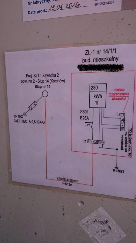
    The figure shows that the network is TN-C, under the meter (photo above) you can see the division of the PEN conductor into PE and N.
    I do not know why the electrician in the kitchen provided a two-wire cable for lighting, maybe he was suggesting that the lighting fitting is plastic and does not require grounding.
  • #16 17534126
    elpapiotr
    Electrician specialist
    kolchoze wrote:
    I do not know why the electrician in the kitchen provided a two-wire cable for lighting, maybe he was suggesting that the lighting fitting is plastic and does not require grounding.
    Nonsense, electrics defying all rules.
    I repeat once again - it was not an electrician, but an "electrician".
    You need to take this stamp from him and submit an application (preferably where he was taking the exam) to take the certificate.
    Remember that for slightly larger investments (also for building acceptance), the electrician attaches a copy (scan) of the ID card with the qualification certificate to the measurement report. There he writes where and in what committee he passed the exam. Ask for a protocol with attachments and ... it's cooked.
    Although he would put a "comb" on the circuit breaker power terminals, he would eat one.
    No words for something like this.
  • #17 17534488
    DJ_KLIMA
    Level 24  
    Lux controls are? ARE! The subcount is - There IS! Everything works? Mr. Janusz Elektryk took my bread again and exposed his investor to losses. Table and part of the installation to be modernized.
  • #18 17534548
    kortyleski
    Level 43  
    Kolchoze wrote:
    the figure shows that the network is TN-C, under the meter (photo above) you can see the division of the PEN conductor into PE and N.

    I have not seen such flowers. Please make sure.
  • #19 17534617
    Kolchoze
    Level 10  
    kortyleski wrote:
    Kolchoze wrote:
    the figure shows that the network is TN-C, under the meter (photo above) you can see the division of the PEN conductor into PE and N.

    I have not seen such flowers. Please make sure.

    N and PE terminal rails - whether they should be connected (bridged)
  • Helpful post
    #20 17534907
    kortyleski
    Level 43  
    So there can be no bridge in the switchgear. Well, once a PEN has been split, it is not allowed to put it back together. So you can see that the installation was done by paprake. What's in the project anyway? Because either there are discrepancies between the design and execution, or the design is only suitable for toilet paper. Generally a messed up job.
  • Helpful post
    #21 17535208
    Waski85
    Level 13  
    For me, the BCE chapter is in front of the numerator, it has been written several times to the right.
    On the right you can see that one wire goes to the GSW or ground.
    Just a little question, is the red phase wire from the meter to the terminals still in line with the standard?
  • #22 17535348
    Kolchoze
    Level 10  
    Ok, from what my colleagues wrote, I understood that:
    1. The PGE network layout is TN-C
    2. The PEN conductor has been split into PE and N before the meter
    3. Behind the meter, the network layout is TN-S
    4. As the PEN conductor has been separated in the PGE meter box, the PE and N terminal strips should not be connected to each other in the main switchboard in the house.
    5. Install the RCD and replace the B20 circuit breakers with B16.
    Did I understand correctly? If something is wrong, I ask my colleagues for correction and justification
  • #23 17535462
    Waski85
    Level 13  
    Almost because the devil is in the details.
    The installation is made on the basis of the design, but before putting it into use, it should be checked if it will work properly.
    One of the most important tests is to check the IPZ (short-circuit loop impedance) to make sure that the applied short-circuit protections work in a timely manner.
    I'm just learning.
  • ADVERTISEMENT
  • #24 17535660
    Kolchoze
    Level 10  
    Waski85 wrote:
    Almost because the devil is in the details.
    The installation is made on the basis of the design, but before putting it into use, it should be checked if it will work properly.
    One of the most important tests is to check the IPZ (short-circuit loop impedance) to make sure that the applied short-circuit protections work in a timely manner.
    I'm just learning.


    I completely agree with my colleague, but there is a certain but. The ordinary bread eater has no clue about drawings, protocols, and other things. An electrician comes, he is told about a new installation, where what lights and sockets, and that's it. It was only after I started to be interested in electrics that I find terrible mistakes not only in my home :cry:
  • #25 17535761
    Moralny
    Level 13  
    You worry about crap vide N-PE bridge and you don't pay attention to important things. You have a terrible porridge under the circuit breakers. 1.5mm cable will not withstand such a load, besides, you have 3 wires of different cross-section on one terminal. I give at most a month of this configuration. And buy a fire extinguisher if you want to use it.
    N and PE terminal rails - whether they should be connected (bridged)
  • #26 17536327
    Anonymous
    Level 1  
  • #27 17536814
    kortyleski
    Level 43  
    Moralny wrote:
    You worry about crap vide N-PE bridge and you don't pay attention to important things.

    It is this bridge that is the most important because it makes the protective conductor between the connector and the switchboard the working conductor. In addition, it creates two cores in one cable connected in parallel. As for the quality of the switchgear, I wrote earlier.
    plum1978 wrote:
    The network of the distribution company is TN-C or TT, there is no supply network in TN-CS or TN-S. You complete the chapter near the building.

    After all, we write about TN-C separated in the junction from the beginning. Who and where ordered the separation at the building?

    Kolchoze wrote:
    I am asking colleagues for correction and justification

    I asked about the project. There is at all?
  • #28 17537586
    Kolchoze
    Level 10  
    kortyleski wrote:
    I asked about the project. There is at all?


    The project is not there. I bought a house for renovation, an electrician came, wrote me what I should buy and made the entire electrical installation in copper (the previous one was in aluminum). A second electrician came to make a connection. It all works for two years. 15 years have passed between the first electrician and the second one, before that there was a sub-meter from a neighbor. Only now, when I start getting into electrical issues, I find many shortcomings that I want to straighten out.
  • #29 17538216
    kkas12
    Level 43  
    Kolchoze wrote:
    ... there is no PE strip in my switchgear because it is connected to the protective conductor (yellow-green) ...
    And this green-yellow wire also known as the protective wire, what letters do you mean?
  • #30 17538220
    Moralny
    Level 13  
    Kolchoze wrote:
    CYRUS2 wrote:
    The PE strip is defined as the one to which the PEN conductor is connected.

    It means that there is no PE strip in my switchgear because it is connected to the protective wire (yellow-green) and to the other strip N there is a blue N conductor?

    Is. But your electrician made a pudding and connected probably randomly ;)

Topic summary

The discussion revolves around the connection of Neutral (N) and Protective Earth (PE) terminal rails in a home electrical switchboard. The original poster notes that in their installation, the N and PE wires are connected via a bridge, raising concerns about safety and compliance with electrical standards. Responses clarify that the N bus and PE bus serve different functions and should not be bridged after the PEN conductor has been split into PE and N. The importance of proper grounding, installation of Residual Current Devices (RCDs), and adherence to electrical codes is emphasized. The conversation highlights the need for corrections in the wiring, including replacing circuit breakers and ensuring all conductors are correctly placed on their respective buses.
Summary generated by the language model.
ADVERTISEMENT