logo elektroda
logo elektroda
X
logo elektroda

Upgrading ROMSTAN BP12/15 Rectifier: Ammeter & Voltmeter Selection, Modifications, & Enhancements

s3tone 9627 19
ADVERTISEMENT
Treść została przetłumaczona polish » english Zobacz oryginalną wersję tematu
  • #1 16176465
    s3tone
    Level 10  
    Hello!

    I would like to improve my ROMSTAN BP12 / 15 rectifier. First of all, I need to replace the ammeter, because the original tip dropped out, by the way I would be tempted to add a voltmeter. Hence my first questions:
    - with what range should you choose an ammeter - up to 5, 8, 10 or 15A?
    - with what range should you choose a voltmeter - up to 15 or 20V?

    The charger is to be used to charge car batteries up to 100Ah, but it will be in the range of 40-80Ah.

    How much can A get out of this transformer? Leave the original adjustment or replace / modify it? Leave the diodes or try to mount the rectifier bridge (some heat sink from the old computer will be found)? Maybe add some protection, although always before connecting the charger to the network, I connect the clamps to the battery terminals and only then turn on the power.

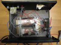
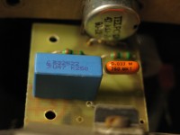
    Here are photos of my rectifier:
    Upgrading ROMSTAN BP12/15 Rectifier: Ammeter & Voltmeter Selection, Modifications, & EnhancementsIMG_34..JPG Download (3.94 MB) Upgrading ROMSTAN BP12/15 Rectifier: Ammeter & Voltmeter Selection, Modifications, & EnhancementsIMG_34..JPG Download (4.02 MB) Upgrading ROMSTAN BP12/15 Rectifier: Ammeter & Voltmeter Selection, Modifications, & EnhancementsIMG_34..JPG Download (3.16 MB)

    [PS] I am not an electrician or electronics specialist, so please write to me like an amateur / idiot :) As if I can use a soldering iron and a meter :D

    Best regards and waiting for advice / suggestions ;)
  • ADVERTISEMENT
  • #2 16176467
    niewolno2
    Level 40  
    If the rectifier is at 15A, then mount such an ammeter as for the voltmeter, then 15V should be suitable. From what I can see this system is implemented on a thyristor plus a power diode.
  • #3 16176473
    s3tone
    Level 10  
    The question is whether this rectifier can actually give 15A, and besides, I will not use more than 10A, so I do not know if it makes sense to mount a "larger" ammeter. I would prefer a "smaller" one, and more accurate - with a larger scale.

    niewolno2 wrote:
    From what I can see this system is implemented on a thyristor plus a power diode.
    thyristor designation: BTA 08 400S 8738N
  • #4 16176484
    Krzysztof Kamienski
    Level 43  
    niewolno2 wrote:
    I see this system is implemented on a thyristor plus a power diode.
    What ??? What nonsense :D Because here I see the regulation on triac in the primary circuit - typical and a full-wave secondary circuit on two diodes. Not much to improve here, apart from the addition of measuring instruments - an ammeter - necessary, a voltmeter as ..... additional.
  • #5 16176587
    gimak
    Level 41  
    Krzysztof Kamienski wrote:
    Not much to improve here, apart from the addition of measuring instruments - an ammeter - necessary, a voltmeter as ..... additional.

    Instead of pointer meters, I would install: Module voltmeter 0-99.9V ammeter 10A shunt (5715282641),
    and additionally - some simple control system of the battery charge status, or actually the voltage of the battery being charged, as protection against its overcharging.
  • ADVERTISEMENT
  • #6 16176752
    jaga134
    Level 26  
    This transformer will be hot already at the 5A charging current. LCD or LED indicators need their own power supply, so again an additional transformer and power supply .... According to me, it is enough to install a new 15A ammeter, e.g. DH-50 2153 and as an additional voltmeter. Why, it is important to charge the battery when charging the battery the charging current and the voltmeter only shows the voltage at the terminals of the battery being charged, and these increase as the charging time passes. Oh, because I can't see clearly where the rectifier diodes are? Because I see for sure one BT type thyristor or rather Russian KU and the other element, which can be a 10A diode but it can also be a thyristor. I would like to have a diagram of this interesting system.
  • #7 16176896
    gimak
    Level 41  
    jaga134 wrote:
    Why bajer, because the charging current is important when charging the battery and the voltmeter shows only the voltage at the terminals of the battery being charged, and these increase as the time of charging increases.

    This is not a baster, but with today's maintenance-free batteries it is quite important, because it allows you to some extent control the battery charge status. It is through the measurement of the voltage of the battery being charged that the automatic overcharge protection systems are implemented in the rectifiers.
    jaga134 wrote:
    LCD or LED indicators need their own power supply so again an additional transformer and power supply ....

    The module (2 in 1 - with Allegro), which I gave as an example, does not need any additional power supply, uses the voltage provided by the battery being charged.
    jaga134 wrote:
    I would like to have a diagram of this interesting system.

    Is it to me
  • ADVERTISEMENT
  • #8 16176914
    robokop
    VIP Meritorious for electroda.pl
    'Someone has already processed, two Russian thyristors stuck in, with gates shorted resistors - they work as ordinary diodes. I would dump it all and buy a real rectifier.
  • #9 16176967
    jaga134
    Level 26  
    Thank you. Col. robokop sufficiently explained what thyristors do in this system.
  • ADVERTISEMENT
  • #10 16177350
    niewolno2
    Level 40  
    Krzysztof Kamienski wrote:
    What ??? What nonsense :D

    Not just nonsense.
    robokop wrote:
    'Someone has already processed, two Russian thyristors stuck in, with gates shorted resistors - they work as ordinary diodes. I would dump it all and buy a real rectifier.
  • #11 16177480
    s3tone
    Level 10  
    jaga134 wrote:
    Because I see for sure one BT type thyristor or rather Russian KU and the other element, which can be a 10A diode but it can also be a thyristor.
    Both elements are KY202B :D

    robokop wrote:
    I would dump it all and buy a real rectifier.
    It is a shame about me for some real rectifier, which I will use very occasionally. I currently borrowed the ABSAAR 11 AMP charger (automatic), and after connecting it to a battery discharged slightly below 12V, it almost burned because it fed it with a current of over 11A (according to the built-in ammeter) and immediately after connecting it buzzed, and after a few minutes he buzzed. Of course, I disconnected it, and when I checked the temperature of the housing to which the rectifier module is screwed, I got burned. Also, I would prefer not to buy new rectifiers, because I do not trust them, especially those without any adjustment of the charging current. In addition, I am of the opinion that old equipment is much more resistant and durable than what is currently coming out of production.

    Is this device really so weak that there is no point in modifying it?
  • #12 16177490
    robokop
    VIP Meritorious for electroda.pl
    s3tone wrote:
    In fact, this equipment is so weak that it makes no sense to modify it
    It's trash, built massively at minimal cost. Neither durable nor economical.
  • #13 16177496
    niewolno2
    Level 40  
    The ammeter and voltmeter you can insert will only improve the convenience and functionality of the rectifier, and as for semiconductors you decide.
  • #14 16177743
    s3tone
    Level 10  
    Is it sense to pack a rectifier bridge there or leave it as it is with these thyristors
  • #15 16177843
    Zygaqra
    Level 35  
    I don't know why someone was pushing the thyristors there, maybe because of the lack of LEDs of adequate power. I had such a rectifier In the current regulator system there was of course a triac and this system controlled the transformer primary winding. Double secondary winding and two diodes as far as I remember 10A. If the ammeter is to be more accurate, it is definitely not like the original one was magnetoelectric with a shunt. The voltmeter, if the budget is right there, gives a lot of information about the charging stage.
  • #17 16178779
    zdzisiek1979
    Level 39  
    And once I wanted to buy one :D

    All modifications are pointless. As a pseudo lambo bohemian with a pseudo Porsche I guess. What came out can be seen :D
    Sorki, but the rectifier is a simple design and therefore not unreliable to those whirlpools with LEDs and microprocessors.

    In such rectifiers, the ammeter simply does for the end of charge indicator.

    I once wanted to replace my ammeter with a better one (better class) but I gave it some rest because what will it give me? THREAD.
  • #18 16178879
    akytam
    Level 17  
    If the voltmeter is on A you have a digital module with an accuracy of 0.1V for 10pln with delivery.
  • #19 16179247
    PEPE64
    Level 16  
    Hello buddy s3tone. If, as you write, you know how to use a soldering iron, I suggest you supplement this rectifier with the AVT2715 attachment. You can order ready or assemble it yourself. Or if you want to opt out of these diodes, or rather thyristors (and by the way it goes with the triac on the original one), you can also order the AVT3120 adapter, which has a bridge with a heat sink, as well as current regulation 1-10A. There is also LED signaling, but you can insert the ammeter as much as possible. After these modifications, the rectifier will be better than many new crap from the market :)
  • #20 21091364
    gimak
    Level 41  
    piotrekwnaw1 wrote:
    What if the shunt is built into the ammeter ? Just solder into the wire - ?
    It is then the wires from the module going to the shunt that you connect into the minus wire for battery charging instead of the external shunt.

Topic summary

The discussion revolves around upgrading the ROMSTAN BP12/15 rectifier, focusing on the selection of an ammeter and voltmeter, as well as potential modifications. Users suggest that for an ammeter, a range of 10A is sufficient, while a voltmeter should ideally be rated for 15V. Concerns are raised about the rectifier's ability to handle 15A, with recommendations for a more accurate ammeter and the addition of a voltmeter to monitor battery charging status. Some participants propose replacing the existing thyristors with a rectifier bridge for improved performance, while others argue that the original design is adequate for occasional use. Suggestions for specific models include the DH-50 2153 ammeter and various digital modules for voltage and current measurement. The conversation highlights the importance of monitoring battery voltage to prevent overcharging and discusses the feasibility of modifications versus purchasing new equipment.
Summary generated by the language model.
ADVERTISEMENT