logo elektroda
logo elektroda
X
logo elektroda

Create a 1kW 30V On-Grid Inverter for Micro-Source Energy: DIY Construction, Efficiency & Design

Charles Bronson 12828 18
ADVERTISEMENT
Treść została przetłumaczona polish » english Zobacz oryginalną wersję tematu
  • #1 16201436
    Charles Bronson
    Level 14  
    Hello. I am looking for a description of the construction of an inverter that would allow surplus of energy generated in the micro-source to be fed into the power grid. The most commonly seen construction is up to 1kVA and not necessarily MPPT. The micro-source would have a voltage at the maximum point of 30V and a power of approx. 1kW. For now, I do not care about achieving inverter efficiency at> 90%. Please do not write about the conditions of connection to the network or the security of the fire. because most of the forum users are aware of this. Please share your knowledge because the topic of network inverters of your own design on the Internet is silent. Thank you.

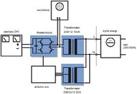
    For "encouragement" I put a scheme of a very simple construction. What do you think about her?
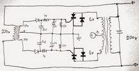
    Create a 1kW 30V On-Grid Inverter for Micro-Source Energy: DIY Construction, Efficiency & Design
  • ADVERTISEMENT
  • #2 16203971
    Lesio_Q
    Level 20  
    What about it can be planted ... missing dots - markings of the beginning of the windings.
    Current from PV will not flow continuously only periodically, i.e. full available power from PV will not be taken.
    It will probably bring a lot of harmonic interference to the network.
    Of course, having no MPPT will have poor performance, and luck will worsen it a bit.
    It is worth trying to throw the system into the simulator.
    The idea of 1959 :|
    Today we have processors.
  • ADVERTISEMENT
  • #3 16215420
    Charles Bronson
    Level 14  
    I tried to build a structure and something like this arose:
    Create a 1kW 30V On-Grid Inverter for Micro-Source Energy: DIY Construction, Efficiency & Design
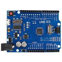
    After a long process of setting the delay times and moments of switching on the "h" bridge branch, it was possible to pump all available energy from the power supply into the network. The power supply gives up a maximum of 20V at 5A. The meter dial clearly indicates the transfer of energy to the network. I used the arduino platform to control the bridge. I wrote a program that, relying on two voltages from a small transformer, turns on the "shredded" PWM DC voltage from the power supply at moments close to the moment when the respective halves of the sine wave reach maximum voltages. Here's a preview of the waveform on the oscilloscope:
    Create a 1kW 30V On-Grid Inverter for Micro-Source Energy: DIY Construction, Efficiency & Design
    It remains for me to solve the problem of regulating the delivered current. In this case, the PWM filling regulation alone gives a regulation range of 30-100%. A regulation of 1% could be used. I did not count the efficiency of the system yet. The case is developmental. Please write any comments about the project. Pzdr.
  • #4 16216923
    Lesio_Q
    Level 20  
    I wonder what the oscillogram looks like on the network side; this PWM probably stays from the core, it is not known how many actually reaches the network.
    And a network harmonic analyzer would be good for you to aim for only 50 Hz injection and as little harmonics as possible.
    Because you have a pumping trafo on "iron" (that is, up to 400 Hz)?
  • #5 16243107
    Charles Bronson
    Level 14  
    Today there was a successful test of my inverter connected to the pv battery panel. All modules were connected "in the spider" and some should be improved (mainly the executive module because it heats up terribly). But despite this the inverter pumped the power nicely into the grid. I decided to share my experience in the construction of this device and describe the most important modules. With today's renewable energy boom, someone can use something and build something interesting on their own.


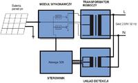
    I divided the construction into four main modules:

    1. WORK TRANSFORMER
    2. DETECTION SYSTEM
    3. DRIVER
    4. IMPLEMENTING MODULE

    by. the following block diagram:

    Create a 1kW 30V On-Grid Inverter for Micro-Source Energy: DIY Construction, Efficiency & Design
  • ADVERTISEMENT
  • #6 16243132
    prose
    Level 35  
    Try instead a transformer at the output on the H-bridge to reduce losses.
  • #7 16243186
    Charles Bronson
    Level 14  
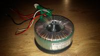
    WORK TRANSFORMER

    I used a toroidal transformer from the Fideltronik Ares 1000 UPS. I don't know the exact parameters of this transformer, but the voltage on the symmetrical secondary winding in idle state is about 2 x 16 V. I estimate the power "safely" at about 500 VA.
    Create a 1kW 30V On-Grid Inverter for Micro-Source Energy: DIY Construction, Efficiency & Design


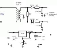
    DETECTION SYSTEM

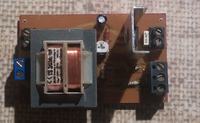
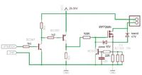
    For the correct detection of the peaks of the respective halves of the sine wave I used a very simple system from the diagram below. It works great so far. As there is some space on the laminate, I decided to put on the board an additional 12 V stabilizer needed to power the arduino and cooling fan.

    Create a 1kW 30V On-Grid Inverter for Micro-Source Energy: DIY Construction, Efficiency & Design
    Create a 1kW 30V On-Grid Inverter for Micro-Source Energy: DIY Construction, Efficiency & Design


    CONTROLLER

    Create a 1kW 30V On-Grid Inverter for Micro-Source Energy: DIY Construction, Efficiency & Design
    You don't need special comment here. The program code is constantly changing. Ready to put in when I consider it final.


    IMPLEMENTING MODULE

    This is an important element of the device. The first design works, but at 16 A currents it gets very hot. Small heat sinks, thin paths. I decided to build a new module.
    Here is the first module:
    Create a 1kW 30V On-Grid Inverter for Micro-Source Energy: DIY Construction, Efficiency & Design
    Create a 1kW 30V On-Grid Inverter for Micro-Source Energy: DIY Construction, Efficiency & Design


    prose wrote:
    Try instead a transformer at the output on the H-bridge to reduce losses.


    I will finish this construction for now. In the meantime I'm building a "h" bridge with drivers. It is possible that I will use it for an inverter. It should be remembered, however, that anyway you need to increase the voltage to be able to pump energy to the grid. And making a DC / DC 24V / 320V converter with 0.5 kW power (because such would be needed in my case) is a piece of craft. Using a line transformer to increase the voltage at a low network frequency seems simpler in workshop conditions.
  • #8 16243683
    krzysiek_krm
    Level 40  
    Hello,
    see the application below:
    http://ww1.microchip.com/downloads/en/AppNotes/01444A.pdf
    slightly different from your expectations but you can always modify the project creatively.
    On the other hand, the solution can be scaled, that is, instead of one large you can use several small ones and one will come out.

    greetings
  • #9 16243754
    prose
    Level 35  
    Charles Bronson wrote:
    Using a line transformer to increase the voltage at a low network frequency seems simpler in workshop conditions.
    Insert at the output goes to the mosfeta network so that it cuts off the power consumption from the network after a voltage drop at the Pv input.
  • #10 16245098
    Charles Bronson
    Level 14  
    IMPLEMENTING MODULE cont

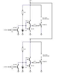
    I built a new module according to scheme below, but there are problems that I can't solve. The module connected to the transformer itself still consumes current because the transistors are "semi-open". The module is controlled with an arduino 50 Hz rectangular waveform during testing, which means that everything would work like a simple voltage converter. There is 3.2 V on the first goal and 3.3 V on the second goal. Of course, everything gets very warm. Where to look for a problem

    Create a 1kW 30V On-Grid Inverter for Micro-Source Energy: DIY Construction, Efficiency & Design
  • #11 16247210
    Lesio_Q
    Level 20  
    In such a system, the MOSFET gate can get 24V - that's too much.
    And for the rest of the scheme - draw it in LTSpice (it's free) and you'll see how it works.
  • #12 16247258
    krzysiek_krm
    Level 40  
    Lesio_Q wrote:
    In such a system, the MOSFET gate can get 24V - that's too much.

    Rather not, there is a 15 V zener diode.
    I would suggest using MOSFET integrated drivers.
    The configuration of transistors is the simplest possible (low - side), there are plenty of ready drivers for this configuration, generally cheap as borscht. They have inputs consistent with the logic from 3 V up, there are systems with output currents at such a level that they can be freely pulled really large structures.

    greetings
  • #13 16247963
    Charles Bronson
    Level 14  
    Lesio_Q wrote:

    And for the rest of the scheme - draw it in LTSpice (it's free) and you'll see how it works.


    Thank you Lesio-Q. Problem solved. The module works perfectly only (I'm ashamed to admit that I did not notice) is controlled by "zero" and not "one". This is beautifully seen in the simulation at LTSpice.
    Create a 1kW 30V On-Grid Inverter for Micro-Source Energy: DIY Construction, Efficiency & Design

    Later, testing the module with a standard 12 V light bulb and feeding "manually" to the low and high state input assured me 100%.
  • ADVERTISEMENT
  • #14 16257415
    Charles Bronson
    Level 14  
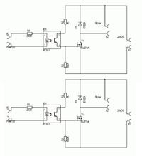
    The executive module controlled "LOW" does not pass the exam in my design. I returned to the old module. Unfortunately, I burned the mosfets because arduino became quite capricious when reloading the program with various inserts such as "Serial.begin" or "if". He sometimes sends him a transient signal, a peak, to the outputs and when he hits the wrong moment, mosfets are burning (IRF540, previously they were IRFZ44N and worked longer). Now I need a module in which the transistors will be protected against overvoltage and short circuit. And it must be controlled by a high state, i.e. entering "HIGH" on the input will open the selected transistor. The system is to operate at a voltage of up to 35 V and not exceed a current consumption of 20A. Searching our forum, I gathered information and put together the following diagram (half of the module):
    Create a 1kW 30V On-Grid Inverter for Micro-Source Energy: DIY Construction, Efficiency & Design
    Can I proceed with the assembly, or do you see any oversights? Of course, there will be a fuse before all this.

    Nobody reports anything, so I get to work.
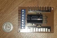
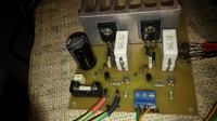
    Ready executive module;
    Create a 1kW 30V On-Grid Inverter for Micro-Source Energy: DIY Construction, Efficiency & Design
  • #15 16269311
    Krek15
    Level 15  
    Construction costs are probably much smaller, but as it relates to security and parameters of working with a power grid is another matter. Still, the idea deserves attention.
  • #16 16270040
    krzysiek_krm
    Level 40  
    Hello,
    layout from last schematic may not work well.
    The mosfet will turn on quickly but shutdown will be very slow, via a 10 k? resistor. In addition, quite high supply voltage forces the use of a Zener diode, when switched on through a 47 ? gate resistor and through this diode a very high current will flow, the elements will heat up.
    As I wrote before, it makes no sense to reinvent the wheel, the easiest way is to use integrated Mosfet drivers, a very large selection, low prices, problems will disappear as you took it away.

    In order for these arduines to generate control pulses smoothly and without jams, you must unfortunately nest the control in the interrupt system.

    greetings
  • #17 16301003
    Charles Bronson
    Level 14  
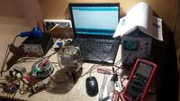
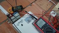
    Although today is a cloudy day, I managed to put everything together and check. First on the table:
    Create a 1kW 30V On-Grid Inverter for Micro-Source Energy: DIY Construction, Efficiency & Design
    And then in the field with the system connected to pv panels:
    Create a 1kW 30V On-Grid Inverter for Micro-Source Energy: DIY Construction, Efficiency & Design
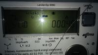
    The system took 23.5V x 4.0A power from panels = 94W . The energy meter, and later also the multimeter indicated the current flow in the "direction to the network" with a value of 0.45A, which roughly corresponds to the power output 0.45A x 230V = 103,5W ! I know there are no perpetual motion devices, but I have a big problem here. I don't know how to explain it. I measured these values in different ways. Weather - uniform, cloudy. The multimeter has the "TrueRMS" function. I attach photos of the meter reading and waveform from the oscilloscope connected to the auxiliary winding of the working transformer.
    Create a 1kW 30V On-Grid Inverter for Micro-Source Energy: DIY Construction, Efficiency & Design
    Create a 1kW 30V On-Grid Inverter for Micro-Source Energy: DIY Construction, Efficiency & Design

    At this time, I stop working on the inverter due to incorrect energy calculations, which has unpleasant legal consequences.

    Added after 9 [minutes]:

    krzysiek_krm wrote:

    As I wrote before, it makes no sense to reinvent the wheel, the easiest way is to use integrated Mosfet drivers, a very large selection, low prices, problems will disappear as you took it away.
    In order for these arduines to generate control pulses smoothly and without jams, you must unfortunately nest the control in the interrupt system.
    greetings


    Thanks for the attention. In the last tested version of the executive module I used transistors IRFP260N plus transile. For now, this combination withstands tests. If it burns, then I will write a program with interrupts. With these drivers I have that I just have a small electronic item and I wanted to make it a sensible driver for satisfaction.
  • #18 16301039
    Lesio_Q
    Level 20  
    Have you reset the clamp on DCA? (after putting on and taking off)
    Can verify these 4A by direct measurement.
  • #19 16301048
    Charles Bronson
    Level 14  
    Verified. I measured currents (from panels and to the network) with clamps and directly with a multimeter from TrueRMS. There are small fluctuations, but the power delivered always comes out greater. Maybe it's something with reactive energy?

    Added after 6 [hours] 46 [minutes]:

    Later it was 22V x 2.6A = 57.2W taken from panels and 0.39A x 230V = 89.7W put into the network, which is even more interesting. Or maybe this Landis Gyr meter cannot cope with low powers and counts energy incorrectly?

Topic summary

The discussion revolves around the construction of a DIY 1kW, 30V on-grid inverter for micro-source energy systems. The initial inquiry highlights the need for a simple inverter design that can feed surplus energy into the grid without focusing on high efficiency or MPPT. Participants share various insights, including the importance of transformer selection, PWM control using Arduino, and the challenges of managing harmonics and current regulation. A successful prototype was developed, utilizing a toroidal transformer from a Fideltronik Ares 1000 UPS, and various modules were outlined: work transformer, detection system, driver, and implementing module. Issues such as overheating components and MOSFET control were discussed, with suggestions for using integrated MOSFET drivers to improve performance. The conversation also touched on measurement discrepancies in power output and the potential influence of reactive energy on readings.
Summary generated by the language model.
ADVERTISEMENT