logo elektroda
logo elektroda
X
logo elektroda

Understanding the Control of Renault Megane II 1.6 16V Variable Valve Timing Solenoid

scott37 15132 14
Best answers LABEL_AI_GENERATED

How is the Renault Megane II 1.6 16V variable valve timing solenoid controlled, and why does it show 12 V without operating or lighting a test bulb?

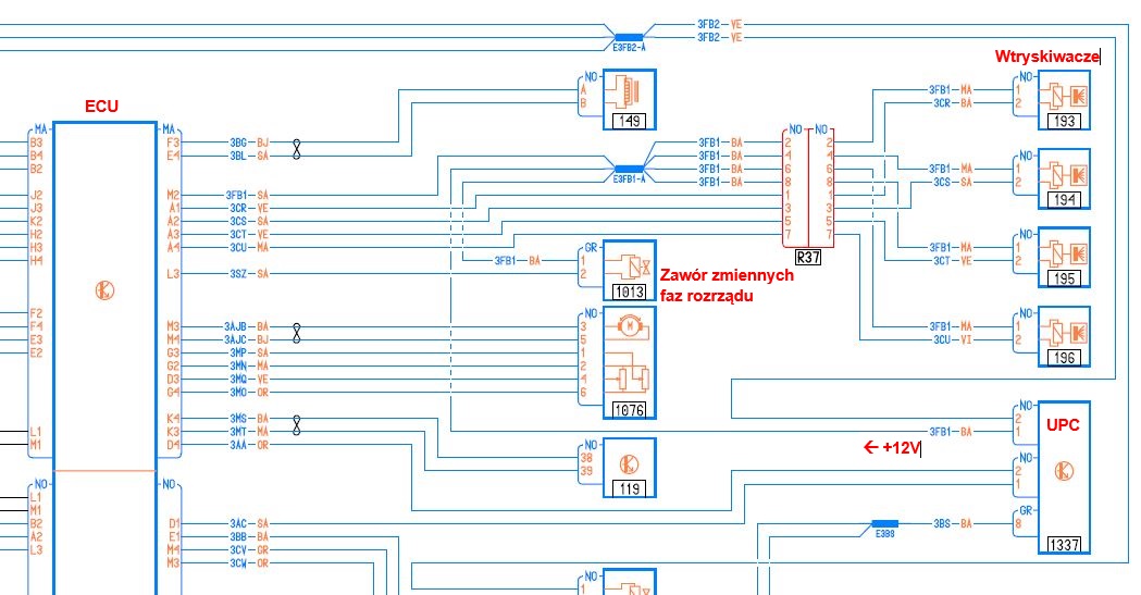
The solenoid receives a constant +12 V supply from the UPC after ignition, while the Sagem ECU controls it by switching the other wire to ground. [#16237055] [#16237120] A multimeter can show 12 V even when a corroded wire, connector, or harness junction cannot deliver enough current, so test the supply under load with a bulb connected to battery negative; it should illuminate. [#21949737] [#21950189] The ECU drives the solenoid using PWM, and the control wire may read approximately 12 V when inactive and approach 0 V when activated. [#21950253] A bulb lighting on the supply and ECU wires proves the wiring can carry some load, but it does not by itself confirm correct PWM operation; the ECU also monitors the output and the camshaft/crankshaft signals during diagnosis. [#21950253]
AI summary based on the discussion. May contain errors.
ADVERTISEMENT
Treść została przetłumaczona polish » english Zobacz oryginalną wersję tematu
  • Clarifying ground-side VVT solenoid control and load testing

    #1 16237003
    scott37
    Level 10  
    Posts: 81
    Rate: 68
    I wanted to ask how it is with the control of the above. solenoid valve, from what I've learned, is controlled by mass. One I do not understand, because after ignition, when I measure with an electronic meter it is 12V, and when I connect the removed solenoid valve, it does not move, when I connect the light bulb, it is not lit either, the plug is 12V, and the solenoid valve does not work, nor the bulb. For my mind this should be how it is and it is clear to me how in the power pressure sensor, through its pins the mass is passed (-) to say some pin in the sagem controller, and here it is like 12V and I can't connect anything - like this is ?
  • ADVERTISEMENT
  • #2 16237055
    m789
    Level 16  
    Posts: 84
    Help: 23
    Rate: 56
    + 12V is given from UPC, the mass is controlled by the controller. As on the meter you have 12V and the connected bulb does not light up, the poor contact in the plug or the wire has rotted.
  • ADVERTISEMENT
  • #3 16237080
    scott37
    Level 10  
    Posts: 81
    Rate: 68
    Everything is correct, you think well, but probably not quite in your opinion, even if there was a 12 ignition position, the solenoid valve would be open all the time, which means that the control is done otherwise.
  • #4 16237120
    m789
    Level 16  
    Posts: 84
    Help: 23
    Rate: 56
    + 12V you have always given (after ignition) and the controller closes the circuit to ground. I don't remember if this valve is normally closed or open. If you connect a light bulb between pin 1 in the plug of this valve and the ground it is to shine. Schemacik
    Understanding the Control of Renault Megane II 1.6 16V Variable Valve Timing Solenoidk4m.JPG (161 kB)You must be logged in to download this attachment.
  • ADVERTISEMENT
  • #5 21949737
    SecurePhotodiode
    Level 3  
    Posts: 5
    Hello,
    On my ignition circuit, one pin reads 12.5 V and the other (ground) reads 2.5 V. I’ve checked the cable to the ECU and it’s fine. Something’s not right, because the solenoid valve isn’t working – it’s stuck in state 3. The solenoid valve is new (Pierburg) and that didn’t help at all. Do you have any ideas?
  • #6 21950189
    carrot
    Moderator of Cars
    Posts: 8495
    Help: 1315
    Rate: 3603
    If you check the voltage with a multimeter that has an internal resistance in the tens of MΩ, it will show the voltage, but no current will flow because the wire or connection has corroded and has a resistance of, say, 1 kΩ, therefore, to be sure, you should always check the voltage and continuity of the wires using a light bulb – at least a 21W one.
  • Load-test +12 V supply and verify VVT PWM control

    #7 21950253
    BANANvanDYK
    Level 43  
    Posts: 7818
    Help: 1167
    Rate: 2602
    Check that you have a correct +12 V supply on one of the pins relative to earth, but with a light bulb connected as a load. If the light bulb does not come on, there is likely to be a corroded wire at the junction point hidden inside the wiring harness.
    On the other hand, a 2.5 V reading on the wire coming from the ECU does not indicate that the engine control unit or the connection is functioning correctly.
    The solenoid valve is controlled by a PWM signal. At a fixed camshaft angle, the duty cycle is 50% and the valve should stop in a position between opening and closing, i.e. in the ‘stop’ position.
    The ECU monitors the voltage at the control output to determine, during self-diagnostics, whether the solenoid valve is connected (12 V) or disconnected (0 V), or to check the response when the solenoid valve is activated (12 V when not activated, 0 V when activated).
  • Loaded wiring test passes, but DF119 persists after sensor replacement

    #8 21950275
    SecurePhotodiode
    Level 3  
    Posts: 5
    When the ignition is on, I connect a bulb to that one pin and touch it to the negative terminal of the battery, and it lights up.
    I checked the cable from the ECU to the solenoid valve in the same way (i.e. under load) and the bulb lit up then too.
    Unfortunately, the solenoid valve still shows ET084 ‘Camshaft phaser – Status 3’ and ET086 ‘Camshaft phaser control – inactive’.
    In PyClip, error code DF119: Camshaft sensor signal.
    I replaced the solenoid valve (Pierburg), the crankshaft sensor (Valeo) and the camshaft sensors (Valeo). I cleared all the faults in PyClip. It hasn’t helped; the camshaft phase adjuster is still showing Status 3, and error DF119 keeps appearing after starting the engine.
  • ADVERTISEMENT
  • Investigating flywheel timing marks and hidden solenoid filter

    #9 21950307
    BANANvanDYK
    Level 43  
    Posts: 7818
    Help: 1167
    Rate: 2602
    DF119, what is the DEF number?
    When did the problem start?
    This fault is probably one of the most puzzling.
    Camshaft position sensor signal mismatch, timing offset, angle outside the KZFR adjustment range.
    When this fault occurs, the variable valve timing solenoid valve will not be controlled.
    I’ve personally heard that with Renault engines, it’s possible to fit the wrong flywheel, one with the markings for the camshaft position sensor in the wrong position. The engine will start, but it won’t run as it should.
    I cannot confirm this information, but the variable valve timing solenoid may have a hidden filter in the oil gallery.
  • Persistent KZFR noise and power loss after timing correction

    #10 21950317
    SecurePhotodiode
    Level 3  
    Posts: 5
    I replaced the timing belt along with the KZFR. Everything was secured with locking clips, as per best practice. After driving about 800 km, a problem arose. When accelerating, it lost a bit of power and the KZFR could be heard from around 2000 rpm. I checked the belt and adjusted the intake camshaft (the one with the KZFR), as the lock on the camshafts wasn’t perfectly aligned. The timing is now perfectly set. Naturally, I carried out all the work with the crankshaft and camshaft locks in place, as well as the wheel chocks. But the problem, as I described above, persists… and I have absolutely no idea what might be causing it.
  • #11 21950428
    carrot
    Moderator of Cars
    Posts: 8495
    Help: 1315
    Rate: 3603
    Since you’re getting a persistent (after starting) fault signal from the camshaft position sensor, it’s obvious that variable valve timing won’t work.
    SecurePhotodiode wrote:
    I’ve replaced the solenoid valve (Pierburg), the crankshaft sensor (Valeo), the camshaft position sensor (Valeo

    What was the point? You’ve spent a fortune and haven’t even checked the signal from the camshaft position sensor
  • #12 21950434
    SecurePhotodiode
    Level 3  
    Posts: 5
    I replaced the solenoid valve because oil kept leaking from the connector.
    How can I check the signal from the camshaft sensor?
  • #13 21950581
    carrot
    Moderator of Cars
    Posts: 8495
    Help: 1315
    Rate: 3603
    Connect an LED with a 680Ω–1kΩ resistor in series between the sensor’s + power supply and its output (the Hall sensor has an open-collector output)
  • Camshaft signal diagnostics and correct KZFR timing procedure

    #14 21950617
    BANANvanDYK
    Level 43  
    Posts: 7818
    Help: 1167
    Rate: 2602
    In Renault vehicles, this fault code (the equivalent of P0340) can have two possible causes. The question is: what DEF code is displayed with this fault? It could be a loss of signal from the camshaft position sensor, or a mismatch in the signal waveform (misalignment of the timing or a missing tooth on the camshaft, etc.).
    What did you mean when you wrote “the KZFR could be heard from around 2,000 rpm”? Perhaps there is no oil supply to the solenoid valve, or between the solenoid valve and the KZFR (via the bridge and the camshaft)?
    Setting the timing requires a thorough reading and understanding of the repair manual, and those for Renault are written in a very terse and incomprehensible manner (as if translated by a machine).
    The variable valve timing wheel must be locked onto the internal pin in the position of maximum delayed timing. In this position, you must not tighten the bolts via the KZFR, as this may damage it. Nissan, at least, states in its engine manual that the KZFR must be set to the position of maximum advanced timing, forcing compressed air into the oil gallery.

Topic summary

LABEL_AI_GENERATED
The discussion revolves around the control mechanism of the Variable Valve Timing (VVT) solenoid in the Renault Megane II 1.6 16V. The user is experiencing issues where the solenoid does not activate despite measuring 12V at the plug after ignition. Responses indicate that while 12V is supplied from the UPC, the solenoid's operation relies on the controller grounding the circuit. Suggestions include checking for poor contacts in the wiring and clarifying whether the solenoid is normally open or closed. It is recommended to connect a light bulb between the solenoid's pin and ground to test functionality.
AI summary based on the discussion. May contain errors.
ADVERTISEMENT