logo elektroda
logo elektroda
X
logo elektroda

Integra 64 Plus House Security System: ETHM1 Plus, INT-E Control Panel, Bosch Detectors & More

Piotr_Pan 20616 18
ADVERTISEMENT
Treść została przetłumaczona polish » english Zobacz oryginalną wersję tematu
  • #1 16262609
    Piotr_Pan
    Level 8  
    Hello and help colleagues from emergency installations, please.

    Based on the found scheme, I changed and designed the following system to secure the house. Integra 64 plus + ETHM1 plus + INT-E control panel. Bosch detectors + Satel S2 reed switches with tamper loop at the end of soldered resistor R2 2.2k
    Please check and make any comments if I made any mistakes in connecting the components or maybe this is not the right concept

    AWZ512 relays will be connected on the OUT5-OUT7 outputs, although I don't know if they will fit into the electrical box so that they can control the sockets remotely.
    I would like to connect RM85 relays on a DIN rail to control 3 sprinklers and a garage door. The question is whether it's good, think whether it is better to add the INT-ORS module (comes out a little more expensive)
    In addition, if I use RM85, do I have to give a schotyego diode parallel to the coil terminals?
    If I want to add additional signal inside SPW220, can I connect it in parallel with 4003 or better separately?

    Thank you in advance for all your valuable comments.
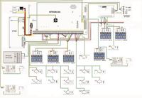
    Integra 64 Plus House Security System: ETHM1 Plus, INT-E Control Panel, Bosch Detectors & More
  • ADVERTISEMENT
  • Helpful post
    #2 16262647
    bartek_p
    Level 31  
    The AWZ 512 relay is not suitable for 230VAC voltage control. It may cause damage to equipment, fire and loss of life.
    As for the scheme itself, you have a concept and try it. None of us knows whether this concept is good.
  • #3 16262651
    bhtom
    Level 38  
    Hello,

    System current balance calculated?
    Why an internal siren with optical and acoustical signaling?

    Greetings.
  • ADVERTISEMENT
  • #4 16262686
    Piotr_Pan
    Level 8  
    Of course, this is about AWZ 514, but what about the RM85 relay connection is this the right approach or INT-ORS?
    Optical-acoustic signaling device. Why? ... that when the alarm is fully armed, both larger dBs for the intruder work, and when switching on, for example, a zone in which there will only be reed switches, it triggers the alarm outside so that it does not get a night attack. Even if you turn it on, there will be increased adrenaline :)
  • #5 16263024
    bhtom
    Level 38  
    Hello,

    Optical, probably only so that in a dark house the intruder could track him down and destroy him ...
    If you want to the night zone, then mount a separate one with adjustable acoustics and turn it down.
    What about the balance?

    Greetings.
  • #6 16263035
    reweriko

    Level 25  
    I also suggest connecting the siren tamper to the alarm line :-) . You have free lines in the module ...
  • #7 16263274
    Piotr_Pan
    Level 8  
    Thanks for the suggestion regarding the sounder with adjustable volume. As for the current balance, I do not know how to calculate it, I understand that for sensors I have these values on the label. However, how does it relate to the load with load.
    I still have free space in the module but there will be rocket detectors there. If I have room, I will of course add a siren.
    Once again, the question regarding the RM85 relays, did any of you install this and can I connect it to the OUT8 - OUTxx outputs
  • ADVERTISEMENT
  • #8 16263377
    reweriko

    Level 25  
    I suspect that nobody will calculate the current balance for you :-) I encourage you to use the "search" button.
    I have the impression that you do not yet know exactly what you want ... what does it mean ... socket control? Draw a diagram will be easier for everyone ....
  • #9 16263498
    Piotr_Pan
    Level 8  
    Electrical sockets will be under AWZ 514. Two sockets for powering the floor lamp in the rooms - this simulation of presence. The third will be the NC for the socket on the terrace and when the alarm is triggered is to cut off the voltage. RM85 are to be connected to 3 solenoid valves for watering and 1 to control the garage door.
  • #10 16264013
    reweriko

    Level 25  
    When it comes to controlling lighting circuits AWZ514 will do its job. However, one thing bothers me .... do you want to "push" them into cans? (I do not recommend). The more that you consider using INT-ORS? So you have the opportunity to do this installation as correctly as possible .. My opinion on this subject is this ... I would only use, for example: RM85 in sockets for DIN rail located in the table. Advantages ... Control from Integra goes to one place, access to the relays mentioned above (in case of damage) is easy, it is possible to connect other circuits than previously assumed, etc .....
  • #11 16264217
    bartek_p
    Level 31  
    And ins-ors is a matter of price and the number of free exits at headquarters. Count what comes out cheaper. Relays have the advantage that you can give one with two contacts and control the pump at the same time, because watering from the network will let you go with the bags.
  • ADVERTISEMENT
  • #12 16264979
    Piotr_Pan
    Level 8  
    Thank you for valuable comments, as for AWZ 514 the choice fell on them because I have already pulled 6 x 0.5 cable to these 3 selected sockets. If I would like to change it to RM85 I would have to plug in the whole circuit in the control room, and this is not really. Maybe you have some other suggestion that the relay could put into a box with a socket, the boxes are deep. RM85 will be for solenoid valves and thanks for your attention regarding the 2-contact relays because I can still do that.
    As for the current balance, I tried to do the job and from what I see it mainly concerns the use of a suitable battery and it will be 17Ah. I have 6 Bosch BPR2 WP12 detectors + 14 reed switches + ethm1 + int-e, 2 sirens, 3xAWZ514, 4x RM85 + 2 carbon monoxide and smoke detectors, so the balance will be OK. Maybe someone has access to the CONFX Satellite program and could help me with an accurate calculation. I am not an installer so I cannot download it.
  • #13 16266003
    wotik
    Level 20  
    Piotr_Pan wrote:
    Electrical sockets will be under AWZ 514. Two sockets for powering the floor lamp in the rooms - this simulation of presence. The third will be the NC for the socket on the terrace and when the alarm is triggered is to cut off the voltage.

    Electrically it will be ok (I skip the issue of stuffing them in cans, because it will be hard), but how are you going to turn on / off these lamps in the rooms in their normal use?
    Maybe take an interest in some typically reed relays?
    Piotr_Pan wrote:
    As for the current balance, I tried to do the job and from what I see it mainly concerns the use of a suitable battery and it will be 17Ah. I have 6 Bosch BPR2 WP12 detectors + 14 reed switches + ethm1 + int-e, 2 sirens, 3xAWZ514, 4x RM85 + 2 carbon monoxide and smoke detectors, so the balance will be OK.

    Add to this the current of the control panel and two keypads you have forgotten. Of course, we count all the maximum currents (yes, I know, some say it is stupid). It turns out to me that the total, maximum current of all devices will be slightly higher than the maximum performance of the integrated power supply. I am not saying that this will be a big problem ... Another issue is the current balance of INDIVIDUAL outputs, but you have to do it yourself ...

    PS. Battery capacity has nothing to do with it ...
  • #14 16267394
    Piotr_Pan
    Level 8  
    Yes, I realize that stuffing can be difficult, so I'm considering making an extra box next to the sockets, although I'd rather avoid it. Maybe someone is able to offer some proven flush relays?
    As for the control is a tablet and smartphone with Integra Control

    Should RM85 be connected in parallel with the diode for the coil terminals?
  • #15 16267483
    dariusz.bembenek
    Stationary Alarms specialist
    Piotr_Pan wrote:
    Should RM85 be connected in parallel with the diode for the coil terminals?

    It's a constant electronics practice. Yes, a diode should be attached - as a preventive measure. And of course only in the reverse direction in relation to the coil control voltage.
  • #16 16271796
    Piotr_Pan
    Level 8  
    @wotik, in fact it turns out to me that the max current for all devices will be slightly higher by some 350mA. In this case it is necessary to add the power supply or rather the situation of reaching max will be difficult to realize in reality.
    I also have a question about the current consumption of the S-2 reed switches in the manual there is only a maximum switching current of 20mA but the switching current is not the max load current, which I think is at the level of 200-500uA max 1mA am I wrong?

    As for the balance of exits, I'm trying to count it myself and I have a question. The Integry 64 Plus specification says that the load capacity of the low-current programmable outputs is 50mA. Is it the load capacity for each OUT5 - OUT16 or total output? If it is the sum, if several AWZ 514 (33mA) and RM85 (35mA) are connected, I am not able to control these relays because max I can connect only one?

    @ dariusz.bembenek, is it better to use a schottky diode or just a simple rectifier?
  • #17 16272198
    dariusz.bembenek
    Stationary Alarms specialist
    Piotr_Pan wrote:
    the load capacity of the low-current programmable outputs is 50mA or is it the load capacity for each OUT5 - OUT16 or total output?

    50mA for each output. Normal rectifying diode (1n4148, 1n4001, 1n4007).
  • #18 16272219
    bhtom
    Level 38  
    Hello,

    Piotr_Pan wrote:
    As for the balance of exits, I'm trying to count it myself and I have a question. The Integry 64 Plus specification says that the load capacity of the low-current programmable outputs is 50mA. Is it the load capacity for each OUT5 - OUT16 or total output? If it is the sum, if several AWZ 514 (33mA) and RM85 (35mA) are connected, I am not able to control these relays because max I can connect only one?


    After all, you only supply AWZ coils from OC outputs, and RMs from another power supply output. In addition, why use two relays if the current of the RM coil does not exceed 50mA?

    Greetings.
  • #19 16273739
    wotik
    Level 20  
    Piotr_Pan wrote:
    @wotik, it really turns out to me that the max current for all devices will be slightly higher by about 350mA. In this case it is necessary to add the power supply or rather the situation of achieving max will be difficult to realize in reality.
    I also have a question about the current consumption of the S-2 reed switches in the manual there is only a maximum switching current of 20mA but the switching current is not the max load current, which I think is at the level of 200-500uA max 1mA am I wrong?

    It all depends on how you finally planned the connection of individual elements, i.e. what the load of each power output will be.
    Do not think about the reeds' current consumption ...

Topic summary

The discussion revolves around the design and implementation of a home security system using the Integra 64 Plus control panel, ETHM1 Plus module, and various Bosch detectors and Satel S2 reed switches. Users provide feedback on the proposed connections, particularly regarding the suitability of AWZ 512 relays for 230VAC control, the use of RM85 relays for controlling sprinklers and a garage door, and the necessity of diodes for relay coils. Concerns about current balance and load capacity for the system's outputs are raised, with suggestions for calculating the current requirements and ensuring proper installation practices. The conversation also touches on the integration of optical-acoustic signaling devices and the potential for using INT-ORS modules for better control.
Summary generated by the language model.
ADVERTISEMENT