I warmly welcome
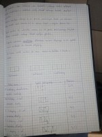
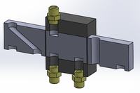
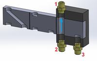
I have a problem understanding how spool valves are shown in the diagrams. I've been thinking about it for a long time and I still don't understand it. I know that the number of positions is determined by the number of squares and that the number of connections shows how many flow paths there are, i.e. what is in the notebook. I also looked on the internet but I couldn't find the answer. I do not understand what indicates that the valve is open or closed and which means that the valve is e.g. 3-way.
I would ask you gentlemen to explain it to me because I cannot understand it myself ?
Thank you in advance, in the attachment I am sending photos from the notebook ?


