logo elektroda
logo elektroda
X
logo elektroda

Analyzing the Correctness of Simple CO Installation Diagram in an Open System with Copper Pipes

Siber2 15291 19
ADVERTISEMENT
Treść została przetłumaczona polish » english Zobacz oryginalną wersję tematu
  • #1 16789619
    Siber2
    Level 2  
    I warmly welcome. I have a great request to those familiar with the topic of a simple diagram of a CO installation in an open system.
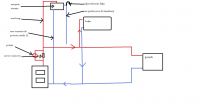
    I put the scheme that I want to do and I have a question if it is correct. The drawing is general, valves, air vents, safety valves, tank protecting the boiler, etc. are coming
    I am asking for an opinion whether the system connected in this way will work properly. The boiler is supposed to work by gravity when the pump turns off, which pushes water to the radiators in a forced system. A detector will be installed in the pump, which will turn it off after the temperature drops, which will prevent the water from cooling out of the DHW. Thank you in advance for any suggestions.
    greetings
    I would like to add that the installation was made of copper, the riser pipe I wanted to give 22 or 25 copper.
    Analyzing the Correctness of Simple CO Installation Diagram in an Open System with Copper Pipes

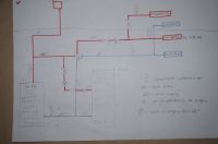
    Installation at this time is done as shown in the second drawing. The expansion vessel plugged into the back with Pex raises my concerns. The differential valve also seems unnecessary to me, since the radiator system works in a forced system, it would be enough to install the pump as in the first drawing. I don't know if I think correctly.
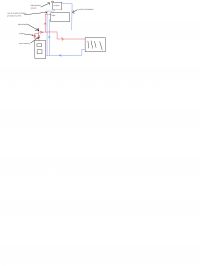
    Analyzing the Correctness of Simple CO Installation Diagram in an Open System with Copper Pipes
  • ADVERTISEMENT
  • #2 16789954
    Anonymous
    Anonymous  
  • #3 16789993
    Siber2
    Level 2  
    Thank you for your answer. Regarding the differential valve - after switching off the pump, e.g. in the absence of gravity current on the radiators, it will not be because the circulation is forced, only gravity will circulate the water to the hot water boiler. The dish will be under the ceiling above the stove, height about 3.2 m.
    Is the diagram in the first drawing correct then?
    The biggest reservations I have about the existing installation presented in the second drawing - a vessel connected with a 15-16 mm pex into the oven. It seems to me that this is not consistent with the so-called safety standards. Do I think right?
  • #4 16790025
    Anonymous
    Anonymous  
  • #5 16790028
    Anonymous
    Anonymous  
  • ADVERTISEMENT
  • #6 16790145
    Siber2
    Level 2  
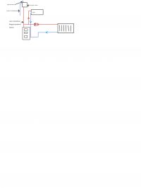
    I also think that the differential valve is unnecessary since after switching off the pump there is no gravity. Before the pump I wanted to connect the boiler so that when the pump was turned off there was gravity on the boiler. As e.g. the water temperature will drop and the pump will turn off it will protect the boiler against cooling down because the radiators will not receive heat. I am not an expert but I think about human logic. The current installation was made by a plumber but it seems to me that it is not necessary "complicated" + a dish that on the pex is probably a mistake. Thank you very much for your reply.

    I drew a modified layout of an existing installation. That the connected vessel will be properly. Analyzing the Correctness of Simple CO Installation Diagram in an Open System with Copper Pipes
  • ADVERTISEMENT
  • #7 16794804
    chudino
    Level 12  
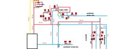
    allow me to hook up on the topic not to set one up on the installation scheme. I am finishing creating my installation and I would like to consult with experts about my project. It is true that he was created with the help of his dad, who is a plumber and makes large boiler rooms, but always with a ready project, and he is not sure what we created. The house will eventually have an area of about 200 sq m, but I won't be able to use the floor, it is 120 sq m. The furnace for now is as it is, garbage truck from Pleszew uks-n 14kw. after renovation it will be changed. Open system, all pipes for steel manifolds (diameters marked in the picture), behind pex wavin 16 manifolds. 4-way valve 6/4 inch, in my opinion a bit to spare but I leave it to your assessment. What do you think about the Biawar WE 220.81 heat exchanger, MEGA 220l heat exchanger, they advised me at the warehouse. The number of thermometers is my idea, I prefer to have everything under control :) thank you in advance for your help and I count on valuable tips Analyzing the Correctness of Simple CO Installation Diagram in an Open System with Copper Pipes
  • ADVERTISEMENT
  • #8 16795428
    gersik
    Level 33  
    Siber2 wrote:
    I drew a modified layout of an existing installation. That the connected vessel will be properly
    No.

    Added after 3 [minutes]:

    chudino wrote:
    I count on valuable tips
    Supply thermometer, give one behind the pump. The temperature will be the same on both distributors. Correct diagram.
  • #9 16795567
    chudino
    Level 12  
    and the diameters of ru, valve and pump ok?
  • #10 16796482
    gersik
    Level 33  
    What are the 80 pumps for? Is this a block?
  • #11 16796713
    chudino
    Level 12  
    gersik wrote:
    What are the 80 pumps for? Is this a block?
    I got 2 new ones and wanted to use it. Their power can cause a problem?
  • #12 16797976
    gersik
    Level 33  
    Unnecessary energy consumption and installation noise may occur.
  • #13 16798007
    chudino
    Level 12  
    What do you recommend for a bunk house? From the stove to the highest point or dishes will be some 7-8m.
  • #15 16817656
    chudino
    Level 12  
    and another question about the size of a 4-way valve. If the installation certainly won't work by gravity and the pump has a DN25 connection, is it a dream to mount a 6/4 inch valve? Maybe to reduce to 1 inch before the valve, give an inch valve and then a inch to the pump?
  • #16 16817814
    gersik
    Level 33  
    If there is no pump in the boiler circuit, then the valve and the entire boiler circuit 6/4 ". Behind the 4d valve you can reduce to 1". After all, you drew all this so why you want to change.
  • #17 16820897
    chudino
    Level 12  
    and because he fooled me in a warehouse guy and claimed that a 1 inch 4d valve is enough
  • #19 16823016
    chudino
    Level 12  
    He has already forgotten to say that :) so I leave it as at the beginning, only with these smaller pumps which you advised me. Thank you for your valuable advice
  • #20 17955248
    wojtek200001
    Level 10  
    Hello. Maybe not in the subject but what do you think about my diagram? I'm getting ready to complete the central one. house 180m2 ground floor oven defro eco 15kw with feeder
    thanks in advance Analyzing the Correctness of Simple CO Installation Diagram in an Open System with Copper Pipes

Topic summary

The discussion revolves around the correctness of a simple CO installation diagram for an open system using copper pipes. The user seeks validation of their design, which includes components like valves, air vents, and safety valves, and aims for gravity operation when the pump is off. Responses highlight the necessity of a differential valve, with some arguing it is unnecessary due to the lack of gravity circulation when the pump is off. Concerns are raised about the existing installation's safety standards, particularly regarding the connection of a vessel with smaller diameter pipes. Additional queries about pump sizes, valve dimensions, and the overall design of the heating system are also addressed, with suggestions for modifications to ensure proper functionality and efficiency.
Summary generated by the language model.
ADVERTISEMENT