logo elektroda
logo elektroda
X
logo elektroda

Adding DM 16 24R Expansion Module to Logo! 8 in Logo Soft Comfort 8.1 Software: Step-by-Step Guide

Schnapsik 15933 14
ADVERTISEMENT
Treść została przetłumaczona polish » english Zobacz oryginalną wersję tematu
  • #1 16433978
    Schnapsik
    Level 7  
    Hello !!!

    I inherited a machine from a colleague to program on the unfortunate Logo! 8, Logo Soft Comfort 8.1 software
    Adding DM 16 24R Expansion Module to Logo! 8 in Logo Soft Comfort 8.1 Software: Step-by-Step Guide

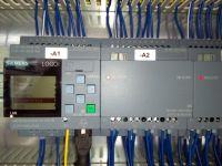
    I cannot or do not know how to add (so far I have only used stepa7 and TIA) the DM 16 24R expansion module. As you can see in the picture, the module is in the foot.

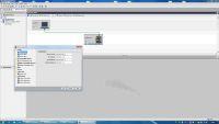
    Below is a screen with the soft comfort logo. As you can see, after clicking Add device, I cannot add DI, DO modules. I do not know if there should be any CD with libraries to be uploaded to the modules, although I do not have any CDs, or maybe you can download a library of external modules from the net.
    Adding DM 16 24R Expansion Module to Logo! 8 in Logo Soft Comfort 8.1 Software: Step-by-Step Guide

    I am asking for a lead, help.

    Thanks in advance
  • ADVERTISEMENT
  • #2 16434144
    arek.m
    Level 22  
    Hello
    It seems to me that the modules are not connected with each other, there are shifts with an arrow on the top of the modules, you need to move them to the left, you need to check if the plugs are removed from the sides of the modules.
    Nothing is added in the program, only exits and entries count.
  • #3 16434445
    Schnapsik
    Level 7  
    Thanks Arek.m for the answer.
    You may be right with these zippers, but the second problem I found is that the Logo supports 24DI and 16DO and I have DM 16 24R 4 times, so I have defacto 32 DI ...

    This is probably the main problem
  • ADVERTISEMENT
  • #4 16440923
    Popak
    Moderator on vacation ...
    @Schnapsik This problem can also be solved :)
    But I don't know if it makes sense. You just add one more logo and connect them to the master and slave and then the maser controls the slave and this one outputs :)
    I used to do this when the logo entered7.


  • #5 16440930
    kracek2
    Level 13  
    Hello
    LOGO 8 supports 20 digital outputs and 24 inputs (as a single relay)
    These gray pins need to be pushed to the left.
    Each new program in Logo Soft Comfort has the maximum I / O and analog configuration at its disposal. This is selected from the tab after selecting an input or an output
  • #6 16441350
    Schnapsik
    Level 7  
    Exactly as kracek2 writes. The gray sliders were not moved, too many modules were attached.

    Popak, I saw that movie. We did without it, but I am puzzled by one thing. Can I upload both cards to the PLC by creating part of the program as Diagram1 and then the second part of the control on Diagram2? Will there be blocks from two diagrams in the PLC then?

    Adding DM 16 24R Expansion Module to Logo! 8 in Logo Soft Comfort 8.1 Software: Step-by-Step Guide
  • #7 16442069
    kracek2
    Level 13  
    Diagram1 is a program for one LOGO
    Diagram2 is for the second.
    This is used if they are networked and you can easily switch between programs
  • #8 16442667
    Schnapsik
    Level 7  
    Thank you !!
  • ADVERTISEMENT
  • #9 16445223
    hemicznyali
    Level 15  
    Popak wrote:
    This problem can also be solved
    But I don't know if it makes sense. You just add one more logo and connect them to the master and slave and then the maser controls the slave and this one outputs

    Popak wrote:
    I used to do this when the logo entered7.

    By combining two modules in a Master-Slave configuration, you will certainly not increase the number of available inputs and outputs.
    If you were to do this, you would know about it.
  • #10 16445854
    Popak
    Moderator on vacation ...
    hemicznyali wrote:
    By combining two modules in a Master-Slave configuration, you will certainly not increase the number of available inputs and outputs.
    If you were to do this, you would know about it.


    And why not increase it?
    The communication is one-way, i.e. only the master controls the slave, vice versa.
    I don't have two logos, so I will show it in the simulator and the output will slowly expand. I quickly made a simple applet showing how to do it by adding four additional outputs on the slave driver. In total, we have 20 exits in the master and four in the slave. A total of 24 exits.
    There are limitations and I am aware of it, but it also depends on the program and what we expect, but the outputs can be easily extended by adding another driver.
    Who didn't do that?

    Link to the video:
    https://youtu.be/qWvkBwSEcws

    Ps. Maybe you have a problem with a program like frankcastel ?
    Or is it still the same person? ;)
  • #11 16445936
    hemicznyali
    Level 15  
    Popak wrote:

    And why not increase it?
    The communication is one-way, i.e. only the master controls the slave, vice versa.
    I don't have two logos, so I will show it in the simulator and the output will slowly expand. I quickly made a simple applet showing how to do it by adding four additional outputs on the slave driver. In total, we have 20 exits in the master and four in the slave. A total of 24 exits.
    There are limitations and I am aware of it, but it also depends on the program and what we expect, but the outputs can be easily extended by adding another driver.
    Who didn't do that?

    Link to the video:
    https://youtu.be/qWvkBwSEcws

    Ps. Maybe you have a problem with a program like frankcastel again?
    Or is it still the same person?

    Because you must learn to read and understand especially what you wrote yourself.
    The video shows Master-Master communication.
    I will not comment on the rest.
  • #12 16446007
    Popak
    Moderator on vacation ...
    hemicznyali wrote:

    Because you must learn to read and understand especially what you wrote yourself.
    The video shows Master-Master communication.
    I will not comment on the rest.


    What a wonderful and substantive statement like here:
    https://www.elektroda.pl/rtvforum/topic3241843.html
    I will not comment on the rest either.
    At least that's where we understand each other :)
  • ADVERTISEMENT
  • #13 16447345
    kracek2
    Level 13  
    Hello
    Gentlemen, maybe this will dispel doubts (excerpt from the LOGO! Manual):

    Master mode vs Slave mode comparison
    LOGO! 0BA8 in normal mode supports client-server connections with SIMATIC S7 PLC modules, SIMATIC HMI panels or other 0BA8 devices in the Ethernet network. This LOGO! it can also work as a Master device when communicating with one or more 0BA8 devices working in the Slave mode. LOGO! in Slave mode it works as an expansion module LOGO !. LOGO! Devices in Slave mode, no application program is required. The LOGO! The master can read the values at the digital / analog inputs / outputs of LOGO! Slaves and write the values to their own digital / analog outputs to these slaves. This allows you to expand the LOGO! Set of network I / O.

    ? network digital inputs: from NI1 to NI64,
    ? network analog inputs: from NAI1 to NAI32,
    ? network digital outputs: from NQ1 to NQ64,
    ? network analog outputs: NAQ1 to NAQ16.
  • #14 16447417
    Popak
    Moderator on vacation ...
    @ kracek2 Thanks for this clipping :)
    Some even try to undermine the instructions written by the manufacturer.
  • #15 17909346
    olisfranek
    Level 9  
    Another question. Do the older expansion modules work with LOGO 8?
    Do I have to buy a LOGO 8 module for LOGO 8?

Topic summary

The discussion revolves around integrating the DM 16 24R expansion module with the Logo! 8 using the Logo Soft Comfort 8.1 software. Users face challenges in adding the module due to potential connection issues and limitations in the number of digital inputs (DI) and outputs (DO) supported by the Logo! 8. It is noted that the Logo! 8 can handle a maximum of 24 DI and 20 DO, and users are advised to ensure that the gray sliders on the modules are properly adjusted. Suggestions include using a Master-Slave configuration to manage additional modules, although this does not increase the total I/O count. Clarifications on programming multiple diagrams for different modules are also provided, emphasizing that each diagram corresponds to a specific Logo! device. The conversation highlights the importance of understanding the device's capabilities and configurations for successful programming.
Summary generated by the language model.
ADVERTISEMENT